1
Non-contact Displacement Measuring
System User’s Manual
Copyright © 2013
PART NO: 860525-001
Last Revised: 8/23/2013
Kaman Precision Products
A Division of Kaman Aerospace Corporation
217 Smith Street
Middletown, CT 06457
www.kamansensors.com
TABLE OF CONTENTS
PART 1 – INTRODUCTION..........................................................................................................4
PART 2 – CONNECTIONS...........................................................................................................5
PART 3 - FRONT PANEL CONTROLS .......................................................................................6
PART 4 – MENU TREE ................................................................................................................7
4.2 mA Out Setup ....................................................................................................................8
4.3 Cal Setup ...........................................................................................................................8
4.4 Linearization Options .........................................................................................................8
4.4.1 2 Pt. Cal ......................................................................................................................8
4.4.2 6 Pt. Poly Cal ..............................................................................................................8
4.4.3 21 Pt. Pcws Cal...........................................................................................................9
4.5 Temperature Compensation ..............................................................................................9
4.6 Display Setup ...................................................................................................................10
4.6.1 Display Percent .........................................................................................................10
4.6.2 Display Voltage .........................................................................................................10
4.6.3 Display Current .........................................................................................................10
4.7 Advanced Setup................................................................................................................10
4.7.1 Digital Filter ...............................................................................................................10
4.7.2 Sample Rate .............................................................................................................10
4.7.3 Ethernet Setup ..........................................................................................................11
4.7.4 Keypad Lockout ........................................................................................................11
4.8 Adjust Output ....................................................................................................................11
4.8.1 Zero Output ................................................................................................................11
4.8.2 2 Pt. Adjust................................................................................................................11
4.8.3 Clear Zero .................................................................................................................11
4.8.4 3 Pt. Adjust................................................................................................................12
PART 5 - ETHERNET OUTPUT .................................................................................................13
5.1 Default IP Address & Ports ..............................................................................................13
5.2 UDP Packet .....................................................................................................................13
5.3 Console Software.............................................................................................................14
PART 6 - CALIBRATION EXAMPLES........................................................................................15
6.1 General Information .........................................................................................................15
6.2 Calibration Fixturing .........................................................................................................16
www.kamansensors.com
PART NO: 860525-001
Last Revised 8/23/2013
-2-
6.3 2-Point Linear Calibration .................................................................................................16
6.4 6-Point Polynomial Calibration ..........................................................................................17
6.5 21-Point Piecewise Calibration .........................................................................................18
6.6 2-Point Adjustment............................................................................................................18
6.7 3-Point Adjustment............................................................................................................19
6.8 Temperature Compensation (Electronics and Sensor) .....................................................19
PART 7 – OTHER FEATURES...................................................................................................21
7.1 Limits & Relay ..................................................................................................................21
7.2 IO bit/AUTOZERO............................................................................................................21
APPENDIX A: COMMAND LIST .................................................................................................22
APPENDIX B: digiVIT STANDARD PROBE OPTIONS..............................................................24
APPENDIX C: digiVIT TYPICAL SPECIFICATIONS .................................................................26
APPENDIX D: CALIBRATION EXAMPLES VIA ETHERNET INTERFACE ...............................27
APPENDIX E: DIMENSIONS......................................................................................................31
APPENDIX F: SOFTWARE LICENSE AGREEMENT ................................................................32
www.kamansensors.com
PART NO: 860525-001
Last Revised 8/23/2013
-3-
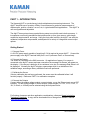
PART 1 – INTRODUCTION
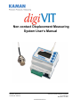
The Kaman digiVIT is a revolutionary inductive displacement measuring instrument. The
digiVIT simplifies use of a variety of Eddy Current sensors for precision measurements of;
displacement, position, vibration, run-out, etc, in typical and difficult applications. The digiVIT is
user configurable and adjustable.
The digiVIT does not require any special factory setup to work with most inductive sensors. It
incorporates a self tuning mechanism that optimizes set up for a given sensor, cable length,
conductive target material, and range. Using the front panel controls, the digiVIT can easily be
calibrated, temperature compensated, and adjusted for a variety of voltage and current output
options.
Getting Started
1.1 Connect Power
A +24 VDC power supply capable of supplying 0.13A is required to power digiVIT. Connect the
power supply to the digiVIT terminal block pins 1 and 2 (reference Part 2 on connections).
1.2 Connect the Sensor
The sensor is connected to the SMA connector. On application of power, if no sensor is
connected or the digiVIT senses and open connection the message 'No Sensor' will appear on
the display. If, the sensor is defective or its resistance is too low, the message 'Bad Sensor' will
be displayed. Normally the digiVIT displays a percentage which is an indication of the
calibrated range, assuming a factory calibration has been performed.
1.3 Calibrate the Sensor
If factory calibration has not been performed, the sensor must be calibrated before it will
function properly. Reference PART 6 on calibration examples.
1.4 Connect the Outputs
Connect either the analog voltage outputs, current outputs, or use the Ethernet port over a UDP
interface. For the analog voltage or current outputs, output ranges (i.e. 0-5V, +/-5V, 0-10V, +/10V, 0-20mA, or 4-20mA) can be selected using the front panel menu.
For fixturing of sensors and other application considerations, reference Kaman’s Inductive
Technology Handbook. A copy can be downloaded free of charge from Kaman’s website:
www.kamansensors.com.
www.kamansensors.com
PART NO: 860525-001
Last Revised 8/23/2013
-4-
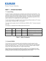
PART 2 – CONNECTIONS
The digiVIT I/O connections are all through a 10 pin removable terminal block. The DigiVIT
sensor is connected through an SMA coaxial connector on the opposite side of the enclosure.
Pin
Name
1
+24V
2
3
4
5
6
7
8
9
10
Gnd
Vout
Gnd
Iout
Gnd
NC
IO
Relay
Relay
Function
+24V Input @ 0.13A
(must accommodate power-on surge current up to 300mA)
Ground
Voltage Output (0-5, +/-5, 0-10, +/-10)
Ground
Curent Loop Output (0-20mA, 4-20mA)
Ground
No Connection
IO Bit for special functions -- standard setup for Autozero when grounded.
Solid State Relay Connection
Solid State Relay Connection
Table 1 Terminal Block Pin-Out
www.kamansensors.com
PART NO: 860525-001
Last Revised 8/23/2013
-5-
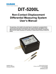
PART 3 - FRONT PANEL CONTROLS
The digiVIT can easily be set up using the front panel controls.
Figure 1 Front Panel Controls
Note: Press and hold the diamond Key (#5 on the figure above) to retune to the Main Menu.
www.kamansensors.com
PART NO: 860525-001
Last Revised 8/23/2013
-6-
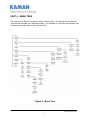
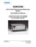
PART 4 – MENU TREE
The menu tree for digiVIT front panel controls is shown below. The up and down arrows will
cycle through the options in a particular branch. If for example, 0-10V output was selected, that
would be the first item shown in the Volt out Setup.
Figure 2 Menu Tree
www.kamansensors.com
PART NO: 860525-001
Last Revised 8/23/2013
-7-
4.1 Volt Out Setup
This option allows selection of the voltage output range from the system.
The actual voltage will go 1% above or below the voltage output range selected if the sensor is
above or below the calibrated range.
4.2 mA Out Setup
This option allows selection of the current output range from the system.
The actual current will go 5% above or below the current output range selected if the sensor is
above or below the calibrated range. In the case of 0-20mA output, it will not go below zero.
4.3 Cal Setup
This selection allows linearization calibration and temperature compensation. With the
exception of the 2 Pt. or 3 Pt. Adjust (reference 4.8) all other calibration methods will zero out
the temperature compensation coefficients and any offset.
4.4 Linearization Options
4.4.1 2 Pt. Cal
The 2 point calibration is useful if either linearity of the output is not a concern or if the sensor is
operated over a very short range. Ranges less than 10% of the standard range (33% of the
sensor diameter) typically will result in good linearity. For ranges below 5% of the standard
range; this is the recommended method.
To perform a 2 Pt calibration, the sensor needs to be position at MAX distance from the sensor
face (i.e. full scale) so that it can optimize for a given sensor. After that, the sensor needs to be
positioned at only the offset (MIN) and full range (MAX) positions.
Any previous temperature compensation calibrations are void when a 2 Pt. calibration is
performed.
4.4.2 6 Pt. Poly Cal
The 6 point polynomial cal fits a 5th order polynomial through the data points to linearize the
sensor output. In most cases this method works very well though there can be exceptions.
The sensor needs to be position at MAX distance from the sensor face (i.e. full scale) so that it
can optimize for a given sensor. After that the sensor needs to be position at offset (MIN) and
then at 20%, 40%, 60%, 80%, and 100% of the range to complete the calibration.
www.kamansensors.com
PART NO: 860525-001
Last Revised 8/23/2013
-8-
Any previous temperature compensation calibrations are void when a 6 Pt. calibration is
performed.
4.4.3 21 Pt. Pcws Cal
This calibration will result in the best performance. It is a 21 point piecewise linearization
method. This option works best if the curve is too oddly shaped for a polynomial to fit well.
The sensor needs to be positioned at the MAX distance from the sensor face (i.e. full scale) so
that it can optimize for a given sensor. After that, it needs to be positioned in 5% of the range
increments from 0-100
Any previous temperature compensation calibrations are void when a 21 Pt. calibration is
performed.
4.5 Temperature Compensation
The digiVIT optimizes the sensor for temperature stability and linearity using proprietary
algorithms. However, even with this optimization, some residual error exists due to
temperature. Temperature stability can generally be improved by a factor of 5-10 using
additional steps to temperature compensate the unit. To perform temperature compensation,
data from 2 different displacements with 2 different temperatures must be acquired by the unit.
The actual displacement does not matter, but typically works best if the displacements are
approximately 10% and 90% of the calibrated range. If the best temperature coefficient is
desired at a particular displacement, that displacement should be chosen as one of the
displacements used. The temperature compensation algorithm will have the smallest
temperature error at that displacement when the calibration is completed. The 4 required points
are:
D1T1 (Displacement 1, Temperature 1)
D1T2 (Displacement 1, Temperature 2)
D2T1 (Displacement 2, Temperature 1), and
D2T2 (Displacement 2, Temperature 2)
in that order.
When temperature compensation is selected, the display shows a temperature relative to when
the calibration process started. It is approximately in degrees Celsius, but is not particularly
accurate in terms of absolute temperature.
The first step is to go to D1T1, it does not matter if it is at the 10% or 90% point (or any point)
and it does not matter what order you take the two temperature points in (rising or falling
temperature). At this displacement change the temperature of the sensor noting the output on
the display. It is best to avoid transients so by heating (or cooling) the sensor it is best to wait
until after any transients have passed to take the data point. The unit does not care what the
actual temperatures used for the calibration are and they do not have to be the same for both
www.kamansensors.com
PART NO: 860525-001
Last Revised 8/23/2013
-9-
displacements. One method is to heat the sensor up some number of degrees, take one data
point after any transients have passed, and take the second data point after it has cooled down
some. After the two temperature points have been collected at displacement 1, then position
the sensor at displacement 2 and take two temperature points again.
If changing the temperature resulted in slight offset and gain errors due to actual position
changes, a 2 or 3 point adjustment calibration can be performed. Temperature coefficients are
not affected.
4.6 Display Setup
The display has several different output options:
4.6.1 Display Percent
Displays the percentage of the calibrated range where the sensor is positioned. Over and under
range will show greater than 100% and less than 0% but the voltage outputs will be constrained
to -1% to +101%. Current outputs are constrained to -5% to +105% (but will not go below
0mA).
4.6.2 Display Voltage
Displays the selected voltage output.
4.6.3 Display Current
Displays the selected current output.
4.7 Advanced Setup
4.7.1 Digital Filter
The display is always filtered but the analog outputs (voltage and current) are not. Resolution of
these outputs can be increased using a digital filter. The time constant options (tau) will vary
slightly depending on the sample rate selected. If the time constant is 0.0 then no filter is used
and only the analog filter and the sample rate matter. The time constant displayed is
representative of how fast the system will respond to a step function. For example, a time
constant of 0.8ms will get to 95% of the step within 3 time constants or 2.4ms.
4.7.2 Sample Rate
The sample rate of the system can be changed from 5,000 to 10,000 samples per second.
5,000 samples per second are adequate for most applications and is the default. 10,000
samples per second can be selected for special applications when required. At 10,000 samples
www.kamansensors.com
PART NO: 860525-001
Last Revised 8/23/2013
- 10 -
per second, communication with the system over the Ethernet port could slow substantially as
the processor is busy most of the time servicing the analog outputs. If analog output only is
required, slower Ethernet communications should not be an issue.
4.7.3 Ethernet Setup
The Ethernet setup allows change of the IP Address and the UDP reader and writer ports for
connection to the unit.
4.7.4 Keypad Lockout
To prevent unauthorized access, the keypad can be disabled. When the keypad is locked out
none of the buttons on the front panel are active. To reactive the keypad press and hold the
diamond and up arrow buttons until the menu reappears.
4.8 Adjust Output
4.8.1 Zero Output
This will set the displayed output of the system to zero. If a unipolar voltage output is selected
(0-5 or 0-10), output will be set to zero when the button is pressed. If a bipolar voltage output is
selected it will reference to 50% (zero for the bipolar output voltage) when the button is pressed.
This does not reset the range, so if a range with a unipolar output at 25% is zeroed, the display
may lose 25% of the output range. You can also zero the output by grounding the IO bit on the
terminal block.
4.8.2 2 Pt. Adjust
The 2 point adjust makes a slight adjustment to an existing calibration. It allows for correction of
installation or slight loading errors in gain and offset. For this calibration the sensor must be
positioned at MIN and MAX with data taken at each point. This adjustment does not optimize
the output further; it simply corrects scale and offset errors. Temperature coefficients are not
changed. It will remove any offset from zeroing the sensor output.
4.8.3 Clear Zero
This will clear the zero offset and return to the calibrated absolute output.
www.kamansensors.com
PART NO: 860525-001
Last Revised 8/23/2013
- 11 -
4.8.4 3 Pt. Adjust
The 3 point adjust makes a slight adjustment to an existing calibration. It allows for correction of
installation or slight loading errors in gain and offset. For this calibration, the sensor must be
positioned at MIN, MID, and MAX with data taken at each point. This adjustment does not
optimize the output further; it simply corrects scale, offset, and small linearity errors.
Temperature coefficients are not changed. It will remove any offset from zeroing the sensor
output. This option is used when more accuracy, but not a full calibration is required.
www.kamansensors.com
PART NO: 860525-001
Last Revised 8/23/2013
- 12 -
PART 5 - ETHERNET OUTPUT
The digiVIT has an Ethernet output that communicates via a UDP/IP protocol. To protect the
packet it is required that any command is preceded by a sequence number and has a checksum
at the end. It has a fixed IP address (which can be changed) and utilizes fixed ports (these can
also be changed) for sending and receiving data.
5.1 Default IP Address & Ports
Default IP Address: 192.168.0.145
Default UDP Writer Port: 55555
Default UDP Reader Port: 55556
5.2 UDP Packet
The packet sent over the UDP port must be preceded by a sequence number and followed by a
checksum. This is necessary because UDP does not guarantee arrival of the packet to the
host. The format of the packet is:
$s<Payload>#CC
Where the $ is the command preface and s is a sequence character from ASCII 'a' to 'z'. When
the digiVIT receives a command, it will respond with the same sequence number sent as the
first character of the string. It is up to the host to determine if the packet arrived in sequence
and to take any action.
The checksum is the last two characters and is preceded by the # sign indicating the checksum
characters follow as the payload length is variable. It is the inverted 8 bit sum of the ASCII
values in the payload including the sequence number.
www.kamansensors.com
PART NO: 860525-001
Last Revised 8/23/2013
- 13 -
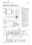
5.3 Console Software
Console software that lets the user enter UDP commands directly is available from Kaman’s
website: www.kamansensors.com. Examples for LabWindows and Labview programs are also
available. Other software that allows more extensive features is also available from Kaman.
Contact a Kaman representative for more information.
The console connects directly to a PC Ethernet port (typically the second Ethernet wireless
connection may have to be disabled as it may attempt to use it). It can also be connected to a
hub or switch or the PC wireless port if configured. It is a simple way of executing the UDP
commands.
Figure 3 Command Console Software Example
www.kamansensors.com
PART NO: 860525-001
Last Revised 8/23/2013
- 14 -
PART 6 - CALIBRATION EXAMPLES
6.1 General Information
There are some rules of thumb when using the digiVIT:
1) The standard range is 1/3 the diameter of the sensor against a non-ferrous target, such
as aluminum.
2) The offset (closest point to sensor face) should be set at 10% of the standard sensor
range.
3) The range against non-magnetic targets can typically be extended to 150% of the
standard range with reduced linearity and thermal sensitivity.
4) Magnetic targets will have a range about 20% of the diameter of the sensor but
performance can vary significantly depending on the material and it's processing.
5) Larger sensor diameters (>35mm) are not as affected by the target material as smaller
diameter sensors and will typically work better with the magnetic targets.
6) When using magnetic targets that are moving laterally to the sensor face (i.e. rotating
targets) the temperature compensation option should not be used (regardless of sensor
diameter). This is due to a 'generator effect' caused by fluctuations in permeability over
the surface of the target influencing the temperature measurement of the sensor.
7) For most ranges, the 6 point calibration will typically yield good to very good results while
the 21 point calibration will give excellent results.
8) When the calibrated range is less than 10% of the standard range a 2 point calibration
will usually yield good results. At ranges less than 5% of the standard range, a 2 point
calibration is recommended.
9) All calibrations can be performed through the front panel or via a UDP command over
the Ethernet interface.
10) For all calibrations, the front panel interface assumes a certain calibration order in the
data points. For calibrations via the UDP interface, data can be taken in any order with
the 'Done command' (C2, C6, CD, or CAM depending on the calibration type) issued
when the calibration is complete.
11) Calibrations can be performed from MIN to MAX range or MAX to MIN range provided
the calibration steps precede sequentially.
Calibration records for 2 point, 6 point, and 21 point calibrations can be downloaded from the
Kaman website: www.kamansensors.com.
www.kamansensors.com
PART NO: 860525-001
Last Revised 8/23/2013
- 15 -
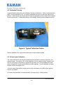
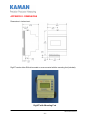
6.2 Calibration Fixturing
A good calibration starts with good calibration fixturing and reference. While in some cases the
digiVIT can be calibrated in-situ, it is typically calibrated using fixturing specially made for the
purpose. Small ranges may require special measuring equipment such as laser interferometers
for the best accuracy. If adequate fixturing is not available, Kaman offers a calibration service.
Figure 4 Typical Calibration Fixture
Refer to Appendix B for typical offset and range of recommended sensors.
6.3 2-Point Linear Calibration
The 2 point calibration is the simplest calibration and assumes the inherent output from the
sensor is linear. Over the first 10% of the range this is true in a general sense, however even
with 5% of the range; non-linearity is typically on the order of 1% of the calibrated full scale
output (though that is a pretty small absolute number typically). Over the standard full range
linearity could be as large as 16%.
1) Set the sensor flush with the target and move the micrometer to the MIN (offset) position.
Zero the micrometer.
2) Position the micrometer at the desired MAX (full scale range + offset) position.
www.kamansensors.com
PART NO: 860525-001
Last Revised 8/23/2013
- 16 -
3) Select 'Cal Setup -> Lineariz Output -> 2 Pt. Lin. Cal.'. The unit will prompt 'Goto MAX Prs
Entr'. With the sensor at MAX press the <enter> button. The unit will prompt 'Scanning Pls
Wait' -- this can take approximately 20 seconds. The unit is optimizing the setup for the
particular sensor, range, and target. Wait for this to finish.
4) The digiVIT will prompt 'Goto MIN Prs Entr'. Position the micrometer to the MIN (offset)
position and press <enter>.
5) The digiVIT will prompt 'Goto 100% Prs Entr'. Position the micrometer to the MAX position
and press <enter>.
The calibration is now complete. If the output reads 100.00% (or close to it) the calibration is
good. If 'Cal Error' is displayed, the digiVIT did not acquire enough analog to digital converter
counts between readings and the calibration sequence must be repeated.
6.4 6-Point Polynomial Calibration
The 6 point calibration is a relatively simple calibration that generally yields excellent results. It
assumes the inherent output from the sensor will have a reasonable fit to a 5th order polynomial
-- generally a good assumption over most ranges. It will result in typical non-linearity on the
order of 0.1% to 0.3%. Most of the procedure is the same as the 2 point calibration except with
more data points. This calibration assumes the range is divided into 5 equal intervals. For
example: a 0.5mm range will be divided into 0.5/5 = 0.1mm intervals.
1) Set the sensor flush with the target and move the micrometer to the MIN (offset) position.
Zero the micrometer.
2) Position the micrometer at the desired MAX (full scale range + offset) position.
3) Select 'Cal Setup -> Lineariz Output -> 6 Pt. Poly Cal.'. The unit will prompt 'Goto MAX Prs
Entr'. With the sensor at full scale press the <enter> button. The unit will prompt 'Scanning Pls
Wait' -- this can take approximately 20 seconds. The unit is optimizing the setup for the
particular sensor, range, and target. Wait for this to finish.
4) The digiVIT will prompt 'Goto MIN Prs Entr'. Go to the MIN position and press <enter>.
5) The digiVIT will prompt 'Goto 20% Prs Entr'. Go to the 20% (0.1mm in our example) position
and press <enter>.
6) Repeat step 5 for 40%, 60%, and 80% positions
7) The digiVIT will prompt 'Goto 100% Prs Entr'. Position the micrometer to the MAX position
and press <enter>.
The calibration is now complete. If the output reads 100.00% (or close to it) the calibration is
good. If 'Cal Error' is displayed, the digiVIT did not acquire enough analog to digital converter
counts between readings and the calibration sequence must be repeated.
www.kamansensors.com
PART NO: 860525-001
Last Revised 8/23/2013
- 17 -
6.5 21-Point Piecewise Calibration
The 21 point calibration requires more displacement positions but is the most flexible and will
calibrate to almost any curve as long as it is monotonic and there is enough output between
sensor data points. If the fixturing is accurate it almost always yields excellent results. This
calibration assumes nothing about the sensor output as it is a piecewise table lookup approach.
It will result in typical non-linearity on the order of 0.1%. Most of the procedure is the same as
the 6 point calibration except with more data points. This procedure assumes the range is
divided into 20 equal intervals. For example: a 0.5mm range is divided into 0.5/20 = 0.025mm
intervals.
1) Set the sensor flush with the target and move the micrometer to the MIN (offset) position.
Zero the micrometer.
2) Position the sensor at the desired MAX (full scale range + offset) position.
3) Select 'Cal Setup -> Lineariz Output -> 21 Pt. Pcws Cal.'. The unit will prompt to 'Goto MAX
Prs Entr'. With the sensor at full scale press the <enter> button. The unit will prompt 'Scanning
Pls Wait' -- this can take approximately 20 seconds. The unit is optimizing the setup for the
particular sensor, range, and target. Wait for this to finish.
4) The digiVIT will prompt 'Goto MIN Prs Entr'. Go to the MIN position and press <enter>.
5) The digiVIT will prompt 'Goto 5% Prs Entr'. Go to the 5% (0.025mm in our example) position
and press <enter>.
7) Repeat step 5 for 10-95% positions.
5) The digiVIT will prompt 'Goto 100% Prs Entr'. Position the micrometer to the MAX position
and press <enter>.
The calibration is now complete. If the output reads 100.00% (or close to it) the calibration is
good. If 'Cal Error' displayed, the digiVIT did not acquire enough analog to digital converter
counts between readings and the calibration sequence must be repeated.
6.6 2-Point Adjustment
This procedure adjusts the calibration curve slightly for variations due to offset differences and
slight target or loading differences. It is only for minor adjustments as it assumes the output
curve has been affected linearly by environment differences.
1) Select 'Adjust Output -> 2 pt. Adjust' and press <enter>.
2) Position the sensor at the MIN (offset) position and press <enter>.
3) Position the sensor at the MAX (full range + offset) position and press <enter>.
www.kamansensors.com
PART NO: 860525-001
Last Revised 8/23/2013
- 18 -
The adjustment is now complete. If the output reads 100.00% (or close to it) the adjustment is
good. If 'Cal Error' is displayed, the adjustment is not good, a full recalibration may be required.
6.7 3-Point Adjustment
This procedure adjusts the calibration curve slightly for variations due to offset differences and
slight target or loading differences. It is only for minor adjustments as it assumes the output
curve has been affected linearly by environment differences.
1) Select 'Adjust Output -> 3 pt. Adjust' and press <enter>.
2) Position the sensor at the MIN (offset) position and press <enter>.
3) Position the sensor at the MID (mid range or 50%) position and press <enter>.
4) Position the sensor at the MAX (full range + offset) position and press <enter>.
The adjustment is now complete. If the output reads 100.00% (or close to it) the adjustment is
good. If 'Cal Error' is displayed, the adjustment is not good, a full recalibration may be required.
6.8 Temperature Compensation (Electronics and Sensor)
While the digiVIT optimizes the sensor output for inherent temperature stability it can be
improved further by temperature compensation. The temperature of the sensor is measured
and used to compensate the output based on equations in the digiVIT. Optionally the
Electronics can also be temperature compensated separately from the sensors and uses a built
in temperature sensor for the compensation. In either case the compensation method is the
same. These equations are set by collecting data at 4 temperature points:
D1T1 -- Displacement 1, Temperature 1
D1T2 -- Displacement 1, Temperature 2
D2T1 -- Displacement 2, Temperature 1
D2T2 -- Displacement 2, Temperature 2
The digiVIT assumes that D1 is the same physical position for both T1 and T2. It does not
assume that the temperature of D2T1 is the same as D1T1.
As with any calibration temperature compensation depends on good fixturing. To some degree
if the fixturing is moving in temperature (due to material coefficient of thermal expansion – CTE)
the same way it does in the application the digiVIT will tend to compensate for it. In many cases
the digiVIT can be temperature compensated in-situ.
It is best to choose points D1 and D2 at 10% and 90% of the range (D1 could be 90% and D2
could be 10% -- does not matter). If the expected usage is in a narrower range, better results
could be obtained in the important displacement band by calibrating over the narrower range.
www.kamansensors.com
PART NO: 860525-001
Last Revised 8/23/2013
- 19 -
1) Select 'Cal Setup -> Temp Cmp Sensor' from the front panel. The prompt will read
'GotoD1T1 relC 0’. At this point it expects to be at Displacement 1 Temperature 1 in a fixture. A
good method is to fixture it at 90% of displacement (approximately -- it does not matter
precisely) and the heat the sensor head (if cable is going to be in the hot environment it should
also be included). You will see the relC x indicator rise as temperature increases and fall as it
decreases. It works best to heat it up and then let it cool down just a bit before taking the first
data point so that transient effects are not included. Typically if the sensor is heated until the rel
C reads 10 or 12 or more that is sufficient. Let it cool down slightly to say 11 or even 9 and
press <enter>.
2) The prompt will read 'GotoD1T2 relC 8'. Let it cool down until it is close to where it started
though it is not necessary to let it cool down all the way. Then press the <enter> button.
3) The prompt will read 'GotoD2T1 relC 1'. Reposition the sensor in the fixturing to be at a
second displacement. Typically 10% of the range is good setting. Again it is best to heat it up,
let the transient go away and press the <enter> button at a rel C of 10 or 12. After the transient
has gone away, press the <enter> button.
4) The prompt will read 'GotoD2T2 relC 9'. After the temperature goes down to near 1 or 2
press the <enter> button and the temperature compensation is complete.
www.kamansensors.com
PART NO: 860525-001
Last Revised 8/23/2013
- 20 -
PART 7 – OTHER FEATURES
7.1 Limits & Relay
The digiVIT contains a solid state relay connected to pins 9 and 10 of the terminal block. This
relay has a 40 ohm closed impedance and is rated for 60V and 100mA. The relay is controlled
by the limit settings and is set up as a window comparator. The hi and lo limits, polarity (NC or
NO), and hysteresis are setup using the UDP commands. By default the relay will be on if the
output is less than 10% or greater than 90% and off otherwise.
To set the limits and relay, the digiVIT must be connected by an Ethernet cable to a PC running
console software. Reference PART 5 of this manual.
The output from the system is from 0 to 100,000 where 100,000 is 100%. The relay is setup the
same way.
For example, a command of SCLL 20000 sets the low limit to 20%.
S(R)CLP x
USER
X = polarity
Polarity
SET(READ) Limit Polarity 0 = NO 1= NC
S(R)CLH xxxx
USER
xx = Hi Limit
Hi Limit
SET(READ) Limit Hi (Signed Long Int)
S(R)CLL xxxxx
USER
xx = Lo Limit
Lo Limit
SET(READ) Limit LO (Signed Long Int)
S(R)CLD xxxx
USER
xx = Hysteresis
Hysteresis
SET(READ) Limit Deadband (Hysteresis)
(Signed Long Int)
Table 2 Relay Commands
7.2 IO bit/AUTOZERO
The IO bit (pin 8) is set up to have the same functionality as zeroing the system from the
console or the front panel menu. The system will zero the output when pin 8 is grounded and
will function normally when it is open. This means if the system is setup for bipolar voltages it
will go to 50% when grounded and 0% for unipolar voltage settings.
Note: this does not move the effective range of the system as it is only offsetting the output
reading. If the sensor is physically at 5% of the range and is zeroed, the bipolar output setting
the output will read 50% but then the linear range will then be 45% to 145%.
www.kamansensors.com
PART NO: 860525-001
Last Revised 8/23/2013
- 21 -
APPENDIX A: COMMAND LIST
The following are the low level commands for the user to program an interface. Many of the
setup commands are read or write. The command starts with an 'S' for a write (such as SCLL
20000) or an 'R' for a read (RCLL will read back the setting). Settings are stored in non-volatile
system memory.
Command
Passlevel Parameters
Required
Returns
Comments
Monitor Commands
MD
NONE
NONE
Distance Output
Monitor Distance Output 100000=100%
ML
NONE
NONE
Monitor Limit
Monitor Limit 0= in range 1=low 2 = hi
MR
NONE
NONE
Monitor Relay
Monitor Relay 0= Open 1 = Closed
ZZ
NONE
NONE
--
Zeroes the output
ZC
NONE
NONE
--
Clears the zero on the output
S(R)CLP x
USER
X = polarity
Polarity
SET(READ) Limit Polarity 0 = NO 1= NC
S(R)CLH xxxx
USER
xx = Hi Limit
Hi Limit
SET(READ) Limit Hi (Signed Long Int)
S(R)CLL xxxxx
USER
xx = Lo Limit
Lo Limit
SET(READ) Limit LO (Signed Long Int)
S(R)CLD xxxx
USER
xx = Hysteresis
Hysteresis
SET(READ) Limit Deadband (Hysteresis)
(Signed Long Int)
S(R)EA xxx xxx xxx xxx
USER
xx xxx xxx xxx =
IP Address
IP Address
SET(READ) Ethernet IP Address
Note: Separate Octets with spaces not '.'
S(R)EW xxxxx
USER
xx = port
UDP Writer Port
SET(READ) Ethernet Writer Port
S(R)ER xxxxx
USER
xx = port
UDP Reader
SET(READ) Ethernet Reader Port
REM
NONE
MAC
READ Ethernet MAC Address
AutoZero Function
Limit Setup
Ethernet Setup
Output Setup
S(R)UI x
USER
x = setting
Setting
S(R)UV x
USER
x = setting
Setting
www.kamansensors.com
SET(READ) User Current Output
0=0-20mA
1=4-20mA
SET(READ) User Voltage output
0=0-5V
1 =+/-5V
2=0-10V
3=+/-10V
PART NO: 860525-001
Last Revised 8/23/2013
- 22 -
Command
Passlevel Parameters
Required
Returns
Comments
System
RXR
NONE
NONE
Revision
Read Firmware Revision
U
NONE
Sets Passlevel
Passlevel 0-2
Unlocks for higher level control
U KAMAN<ret> -- unlocks to User Level
U<ret> -- sets password to normal level
WC
NONE
NONE
Seconds
Watch Clock (seconds since power on)
WT
NONE
NONE
Ticks
Watch Ticks (Ticks since power on)
NONE
NONE
--
MISC TIMER
CALIBRATION
CS
Saves the calibration and all parameters
Set Optimal Full Scale – Sets Frequency and
Optimal Coil Current – sensor must be positioned
at max displacement from sensor. This is the first
thing done in a calibration.
Sets Zero and sets gains and offsets (Executed
after CF) – sensor must be positioned at the
minimum displacement from sensor. This is the
second thing done in a calibration
Cal Point (0-20) for piecewise linearization –
sensor must be positioned at the correct percent of
full scale – i.e. 0=0%, 1=5%,2 =10% … 20=100% - direction (min to max or max to min) does not
matter as long as it changes monotonically. For 6
point polynomial cals only use 0-5 points and they
must be spaced 20% apart ... i.e. pt 0 is 20%, pt1
is 40% ... pt 5 = 100% of range. For a 2 point cal
pt 0 = 0% pt 1 = 100%.
Completes the 21 point calibration and sets up the
tables for operation
CF
NONE
NONE
Frequency
CZ
NONE
NONE
--
CP x
NONE
X = 0-20
AD Reading
CD
NONE
NONE
Status
C6
NONE
NONE
Status
Completes the 6 point polynomial cal
C2
NONE
NONE
Status
Completes the 2 point linear cal
CAZ
NONE
NONE
--
Cal Adjust zero point
CAM
NONE
NONE
--
Cal Adjust mid point
CAF
NONE
NONE
--
Cal Adjust full scale point
CAD
NONE
NONE
Status
Complete 2 Point Adjust
CT 0
NONE
NONE
--
Collect Temp Comp Data for D1T1
CT 1
NONE
NONE
--
Collect Temp Comp Data for D1T2
CT 2
NONE
NONE
--
Collect Temp Comp Data for D2T1
CT 3
NONE
NONE
--
Collect Temp Comp Data for D2T2
CT 4
NONE
NONE
Status
Completes Temperature Compensation for Sensor
CT 5
NONE
NONE
Status
Completes Temperature Compensation for
Electronics
www.kamansensors.com
PART NO: 860525-001
Last Revised 8/23/2013
- 23 -
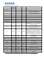
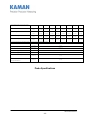
APPENDIX B: digiVIT STANDARD PROBE OPTIONS
Although the digiVIT will work with nearly any sensor and any conductive target, the following sensors
have been characterized over standard ranges with an aluminum target.
www.kamansensors.com
PART NO: 860525-001
Last Revised 8/23/2013
- 24 -
Characterized with an aluminum target
2U
4U
9U
12U
16U
26U
38U
51U
Offset
inch
(mm)
0.002
(0.05)
0.005
(0.13)
0.010
0.25
0.016
(0.40)
0.020
(0.50)
0.032
(0.80)
0.050
(1.20)
0.100
(2.5)
Short range
Inch
(mm)
0.010
(0.25)
0.025
(0.60)
0.050
(1.25)
0.080
(2.00)
0.100
(2.50)
0.160
(4.00)
0.250
(6.00)
0.300
(7.50)
Standard range
Inch
(mm)
0.020
(0.50)
0.050
(1.30)
0.100
(2.50)
0.160
(4.00)
0.200
(5.00)
0.320
(8.00)
0.500
(12.00)
0.600
(15.00)
Extended range
Inch
(mm)
0.030
(0.75)
0.070
(3.75)
0.150
(3.75)
0.240
(6.00)
0.320
(8.00)
0.500
(12.50)
0.800
(20.00)
1.000
(25.00)
Typical specifications for standard range, aluminum target, standard cable length:
+/- %FS
Nonlinearity 6 pt calibration
Nonlinearity 21 pt calibration
Static Resolution
Resolution @ 100Hz
Resolution @1000Hz
Thermal sensitivity
Thermal sensitivity w/temp
comp calibration
<0.3%
+/- %FS
<0.1%
RMS %FS
<0.001%
RMS %FS
<0.01%
RMS %FS
<0.02%
%FS/°F
(%FS/°C)
0.05
(0.1)
%FS/°F
(%FS/°C)
0.01
(0.02)
Probe Specifications
www.kamansensors.com
PART NO: 860525-001
Last Revised 8/23/2013
- 25 -
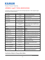
APPENDIX C: digiVIT TYPICAL SPECIFICATIONS
Specifications below are typical but are sensor and target dependent. Some magnetic targets
may not work well with the digiVIT.
Parameter
Specification
Power Supply
+18-28V
Input Current
0.13A
Notes
Current will change with input
At +24V input typical
Voltage Output
0-5V,+/-5V,0-10V,+/-10V
Current Output
0-20mA, 4-20mA
Range
33% of sensor diameter
standard
Offset
10% of range
Voltage and current are simultaneously
output, Outputs will over/under range by 1%
Ranges can vary typically from 5% of the
standard range to 150% of standard range
on non-magnetic targets. Magnetic targets
are highly variable.
1/3000 RMS at full
bandwidth no filtering
Typical
Resolution Static
1/100000 RMS
Typical
Linearity 6 pt. Cal
0.3% of Full Range
Least Squares over standard range typical
Linearity 21 pt. Cal
0.1% of Full Range
Least Squares over standard range typical
Resolution
Targets
Any conductive
Some magnetic targets may not work well or
only over a substantially reduced range
Standard range/AL target Typical sensor
head only -- no cable
Temp Co w/o temp comp
0.1%FR/oC
TempCo w/Temp comp
0.02%FR/oC
Standard range/AL target
Electronics TempCo
0.05-0.1%/oC
Standard range/AL target Typical
W/Electronics Temp Comp 5x typical
improvement
Electronics Temp Range
0-50 oC
Sensor DC Resistance
0.5 to 20 ohms
<0.5 ohms is 'bad sensor', >20 is 'no sensor'
Sensor Inductance
10uH to 50uH
It has been tested with sensors in this range.
It may work with sensors up to 10mH in
special situations not guaranteed.
Specifications Subject to Change without Notice
www.kamansensors.com
PART NO: 860525-001
Last Revised 8/23/2013
- 26 -
APPENDIX D: CALIBRATION EXAMPLES VIA ETHERNET INTERFACE
Calibrations using the Ethernet interface have the same procedure as the examples in Part 6 of
the manual. Data is entered using UDP commands from a PC instead of front panel controls.
To perform these procedures, the digiVIT must be connected by an Ethernet cable to a PC
running console software. Reference PART 5 of this manual.
Refer to Appendix B for typical offset and range of recommended sensors.
D.1 - 2 Point Linear Calibration
1) Set the sensor flush with the target and move the micrometer to the MIN (offset) position.
Zero the micrometer.
2) Position the micrometer at the desired MAX (full scale range + offset) position.
3) With the sensor at full scale, type UDP command ‘CF’. The unit will prompt 'Scanning Pls
Wait' -- this can take approximately 20 seconds. The unit is optimizing the setup for the
particular sensor, range, and target. Wait for this to finish.
4) Position the micrometer to the MIN position (offset). Type ‘CZ’, then ‘CP 0’ to take data.
5) Position the micrometer to the MAX position. Type ‘CP 2’ to take data, then ‘C2’ to
complete the calibration.
The calibration is now complete. If the calibration is good, the digiVIT will return a status of 0. A
status of 1 is returned on a bad calibration and the calibration must be performed again.
D.2 - 6 Point Polynomial Calibration
Most of the procedure is the same as the 2 point calibration except with more data points. This
calibration assumes the range is divided into 5 equal intervals. For example: a 0.5mm range
will be divided into 0.5/5 = 0.1mm intervals.
1) Set the sensor flush with the target and move the micrometer to the MIN (offset) position.
Zero the micrometer.
2) Position the micrometer at the desired MAX (full scale range + offset) position.
3) With the sensor at full scale, type UDP command ‘CF’. The unit will prompt 'Scanning Pls
Wait' -- this can take approximately 20 seconds. The unit is optimizing the setup for the
particular sensor, range, and target. Wait for this to finish.
4) Position the micrometer to the MIN position. Type ‘CZ’, then ‘CP 0’ to take data.
5) Go to the 20% position (0.1mm in our example). Type ‘CP 1’ to take data.
www.kamansensors.com
PART NO: 860525-001
Last Revised 8/23/2013
- 27 -
6) Repeat step 5 for 40%, 60%, and 80% positions. Type 'CP 2', 'CP 3', 'CP 4' at these
positions respectively.
7) Position the micrometer to the MAX position. Type ‘CP 6’ to take data, then ‘C6’ to
complete the 6 point calibration.
The calibration is now complete. If the calibration is good, the digiVIT will return a status of 0. A
status of 1 is returned on a bad calibration and the calibration must be performed again.
D.3 - 21 Point Piecewise Calibration
Most of the procedure is the same as the 6 point calibration except with more data points. This
procedure assumes the range is divided into 20 equal intervals. For example: a 0.5mm range is
divided into 0.5/20 = 0.025mm intervals.
1) Set the sensor flush with the target and move the micrometer to the MIN (offset) position.
Zero the micrometer.
2) Position the micrometer at the desired MAX (full scale range + offset).
3) With the sensor at full scale, type UDP command ‘CF’. The unit will prompt 'Scanning Pls
Wait' -- this can take approximately 20 seconds. The unit is optimizing the setup for the
particular sensor, range, and target. Wait for this to finish.
4) Position the micrometer to the MIN (offset) position. Type ‘CZ’, then ‘CP 0’ to take data.
5) Go to the 5% (0.025mm in our example) position. Type ‘CP 1’ to take data.
6) Repeat step 5 for 10-95% positions. Type 'CP 2', 'CP 3', 'CP 4' … ‘CP19’ at these positions
respectively.
7) Position the micrometer to the MAX position. Type ‘CP 20’ to take data, then ‘CD’ to
complete the 21 point calibration.
The calibration is now complete. If the calibration is good, the digiVIT will return a status of 0. A
status of 1 is returned on a bad calibration and the calibration must be performed again.
www.kamansensors.com
PART NO: 860525-001
Last Revised 8/23/2013
- 28 -
D.4 - 2 Point Adjustment
1) Position the sensor at the MIN (offset) position and type ‘CAZ’.
2) Position the sensor at the MAX (full range + offset) position and type ‘CAF’ to take data, then
‘CAD’ to complete the adjustment.
The adjustment is now complete. If the calibration is good, the digiVIT will return a status of 0.
A status of 1 is returned on a bad adjustment. If the adjustment is not good, a full recalibration
may be required.
D.5 - 3 Point Adjustment
1) Position the sensor at the MIN (offset) position and type ‘CAZ’.
2) Position the sensor at the MID (mid range or 50%) position and type ‘CAM’
3) Position the sensor at the MAX (full range + offset) position and type ‘CAF’ to take data, then
‘CAD’ to complete the adjustment.
The adjustment is now complete. If the calibration is good, the digiVIT will return a status of 0.
A status of 1 is returned on a bad adjustment. If the adjustment is not good, a full recalibration
may be required.
D.6 - Temperature Compensation (Electronics and Sensor)
While the digiVIT optimizes the sensor output for inherent temperature stability it can be
improved further by temperature compensation. The temperature of the sensor is measured
and used to compensate the output based on equations in the digiVIT. Optionally the
Electronics can also be temperature compensated separately from the sensors and uses a built
in temperature sensor for the compensation. In either case the compensation method is the
same. These equations are set by collecting data at 4 temperature points:
D1T1 -- Displacement 1, Temperature 1
D1T2 -- Displacement 1, Temperature 2
D2T1 -- Displacement 2, Temperature 1
D2T2 -- Displacement 2, Temperature 2
The digiVIT assumes that D1 is the same physical position for both T1 and T2. It does not
assume that the temperature of D2T1 is the same as D1T1.
As with any calibration, temperature compensation depends on good fixturing. To some degree
if the fixturing is moving in temperature (due to material coefficient of thermal expansion – CTE)
the same way it does in the application, the digiVIT will tend to compensate for it. In many
cases the digiVIT can be temperature compensated in-situ.
www.kamansensors.com
PART NO: 860525-001
Last Revised 8/23/2013
- 29 -
It is best to choose points D1 and D2 at 10% and 90% of the range (D1 could be 90% and D2
could be 10% -- does not matter). If the expected usage is in a narrower range, better results
could be obtained in the important displacement band by calibrating over the narrower range.
1) Select 'Cal Setup -> Temp Cmp Sensor' from the front panel. The prompt will read
'GotoD1T1 relC 0’. At this point it expects to be at Displacement 1 Temperature 1 in a fixture. A
good method is to fixture it at 90% of displacement (approximately -- it does not matter
precisely) and the heat the sensor head (if cable is going to be in the hot environment it should
also be included). You will see the relC x indicator rise as temperature increases and fall as it
decreases. It works best to heat it up and then let it cool down just a bit before taking the first
data point so that transient effects are not included. Typically if the sensor is heated until the rel
C reads 10 or 12 or more that is sufficient. Let it cool down slightly to say 11 or even 9 and type
‘CT 0’.
2) The prompt will read 'GotoD1T2 relC 8'. Let it cool down until it is close to where it started
though it is not necessary to let it cool down all the way. Then type ‘CT 1’.
3) The prompt will read 'GotoD2T1 relC 1'. Reposition the sensor in the fixturing to be at a
second displacement. Typically 10% of the range is good setting. Again it is best to heat it up,
let the transient go away and press the enter button at a rel C of 10 or 12. After the transient
has gone away, type ‘CT 2’.
4) The prompt will read 'GotoD2T2 relC 9'. After the temperature goes down to near 1
or 2 press type ‘CT 3’. Type ‘CT 4’ to complete this procedure if the compensation is for the
sensor. Or, type ‘CT 5’ to complete this procedure if the compensation is for the electronics.
A 0 is returned on a good and a 1 is returned on a bad temperature compensation. A full
recalibration may be required on a bad calibration.
www.kamansensors.com
PART NO: 860525-001
Last Revised 8/23/2013
- 30 -
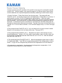
APPENDIX E: DIMENSIONS
Dimensions in inches (mm).
DigiVIT can be either DIN rail mounted or screw mounted with the mounting feet (included).
DigiVIT with Mounting Feet
www.kamansensors.com
PART NO: 860525-001
Last Revised 8/23/2013
- 31 -
APPENDIX F: SOFTWARE LICENSE AGREEMENT
PLEASE READ CAREFULLY - DO NOT DISCARD
THIS IS A LEGAL AGREEMENT.
BY USING THIS SOFTWARE YOU ACCEPT THIS LICENSE AGREEMENT AND
WARRANTY AND
YOU AGREE TO THESE TERMS AND CONDITIONS.
LICENSE. This is a license agreement between you and Kaman Precision Products
("Kaman"). Kaman grants you the non-exclusive right to use the enclosed Kaman software
program ("SOFTWARE") on any computer and there is no restriction on the number of
computers the software can be installed on.
COPYRIGHT AND BACKUP. The SOFTWARE is owned by Kaman or its suppliers and is
protected by United States copyright laws and international treaty provisions. You may make as
many copies of the SOFTWARE for backup or archival purposes as desired, as long as the
copyright and proprietary notices in this license are included in the copy. You may not reverse
engineer, decompile, disassemble, or create derivative works from the software.
You may terminate this license by destroying the
TERMINATION OF LICENSE.
SOFTWARE together with any backup copy. This license will also terminate if you fail to
comply with any term or condition of this Agreement. You agree upon such termination to
destroy the SOFTWARE together with any backup copy of the SOFTWARE.
LIMITED WARRANTY.
Kaman does not warrant that the SOFTWARE will meet your
requirements, that operation of the SOFTWARE will be uninterrupted or error-free, or that all
SOFTWARE errors will be corrected. Kaman is not responsible for problems caused by
changes in the operating characteristics of computer hardware or computer operating systems
which are made after the release of the SOFTWARE nor for problems in the interaction of the
SOFTWARE with non-Kaman software. Kaman will have no responsibility to replace or refund
the license fee of media damaged by accident, abuse, or misapplication.
THE ABOVE WARRANTIES ARE EXCLUSIVE AND IN LIEU OF ALL OTHER WARRANTIES,
EXPRESS OR IMPLIED, INCLUDING WARRANTIES OF MERCHANTABILITY, FITNESS FOR
A PARTICULAR PURPOSE AND NON-INFRINGEMENT.
NO ORAL OR WRITTEN
INFORMATION OR ADVICE GIVEN BY EDI, ITS EMPLOYEES, DISTRIBUTORS, OR
AGENTS SHALL INCREASE THE SCOPE OF THE ABOVE WARRANTIES OR CREATE ANY
NEW WARRANTIES. SOME STATES DO NOT ALLOW THE EXCLUSION OF IMPLIED
WARRANTIES, SO THE ABOVE EXCLUSION MAY NOT APPLY TO YOU. IN THAT EVENT,
ANY IMPLIED WARRANTIES ARE LIMITED IN DURATION TO THIRTY (30) DAYS FROM
THE DATE OF SHIPMENT OF THE SOFTWARE.
LIMITATION OF REMEDIES. IN NO EVENT WILL KAMAN BE LIABLE TO YOU FOR ANY
SPECIAL, CONSEQUENTIAL, INDIRECT OR SIMILAR DAMAGES, INCLUDING ANY LOST
PROFITS OR LOST DATA ARISING OUT OF THE USE OR INABILITY TO USE THE
www.kamansensors.com
PART NO: 860525-001
Last Revised 8/23/2013
- 32 -
SOFTWARE OR ANY DATA SUPPLIED THEREWITH EVEN IF KAMAN OR ANYONE ELSE
HAS BEEN ADVISED OF THE POSSIBILITY OF SUCH DAMAGES OR FOR ANY CLAIM BY
ANY OTHER PARTY. IN NO CASE SHALL KAMAN'S LIABILITY EXCEED THE PURCHASE
PRICE FOR THE SOFTWARE.
GOVERNMENT LICENSEE. If you are acquiring the SOFTWARE on behalf of any unit or
agency of the United States Government, the following provisions apply: The Government
acknowledges KAMAN's representation that the SOFTWARE and its documentation were
developed at private expense and no part thereof is in the public domain.
The Government acknowledges Kaman’s representation that the SOFTWARE is "Restricted
Computer Software" as that term is defined in Clause 52.227-19 of the Federal Acquisition
Regulations (FAR) and is "Commercial Computer Software" as that term is defined in
Subpart 227.471 of the Department of Defense Federal Acquisition Supplement (DFARS). The
Government agrees that: (i) if the SOFTWARE is supplied to the Department of Defense
(DOD), the SOFTWARE is classified as "Commercial Computer Software" and the Government
is acquiring only "restricted rights" in the SOFTWARE and its documentation as that term is
defined in Clause 252.227-7013(c)(1) of the DFARS and (ii) if the SOFTWARE is supplied to
any unit or agency of the United States Government other than DOD, the Government's rights in
the SOFTWARE and its documentation will be as defined in Clause 52.227-19(c)(2) of the FAR.
EXPORT LAW ASSURANCES.
You acknowledge and agree that the SOFTWARE is
subject to restrictions and controls imposed by the United States Export Administration Act (the
"Act") and the regulations hereunder. You agree and certify that neither the SOFTWARE nor
any direct product thereof is being or will be acquired, shipped, transferred or re-exported,
directly or indirectly, into any country prohibited by the Act and the regulations hereunder or will
be used for any purposes prohibited by the same.
GENERAL. This agreement will be governed by the laws of the State of Connecticut. Should
you have any questions concerning this agreement, or if you desire to contact Kaman for any
reason, please write: Kaman Precision Products, 217 Smith Street, Middletown, CT 06457.
www.kamansensors.com
PART NO: 860525-001
Last Revised 8/23/2013
- 33 -