1
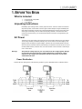
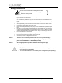
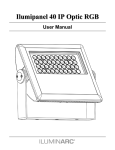
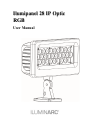
Ilumipanel 28 IP Optic
RGB
User Manual
Edition Notes
The Ilumipanel 28 IP Optic RGB User Manual Rev. 7 covers the description, safety
precautions, installation, programming, operation, and maintenance of the Ilumipanel 28 IP
Optic RGB ILUMINARC® released this edition of the Ilumipanel 28 IP Optic RGB User
Manual Rev. 7 in November 2015.
Trademarks
The ILUMINARC® logo, the ILUMINARC® name and all other trademarks in this
document related to services or products by ILUMINARC® are trademarks owned or
licensed by ILUMINARC®, its affiliates or subsidiaries. Any other product names, logos,
brands, company names or trademarks featured or referred to within this document are the
property of their respective trademark holders.
Copyright Notice
The entire content of this document, except where applicable and unless otherwise noted, is
solely owned by ILUMINARC®, a wholly owned trademark of Chauvet & Sons Inc.
© Copyright 2015 ILUMINARC®
All rights reserved
Electronically published by ILUMINARC® in the United States of America
Manual Usage
ILUMINARC® authorizes its customers to download and print this manual for professional
information purposes only. ILUMINARC® expressly prohibits the usage, copy, storage,
distribution, modification, or printing of this manual or its content for any other purpose
without its written consent.
Document Printing
For better results, print this document in color, on letter size paper (8.5 x 11 inches), double
sided. If using A4 paper (210 x 297 mm), configure your printer to scale the content of this
document to A4 paper.
Intended Audience
Any person in charge of installing, operating and/or maintaining the Ilumipanel 28 IP Optic
RGB should read the Guide that shipped with it and this manual in their entirety before
installing, operating or maintaining this product.
Disclaimer
ILUMINARC® believes that the information contained in this manual is accurate in all
respects. However, ILUMINARC® assumes no responsibility for any error or omissions in
this document. ILUMINARC® reserves the right to revise this document and to make
changes from time to time in the content hereof without obligation of ILUMINARC® to
notify any person or company of such revision or changes. This does not constitute in any
way a commitment by ILUMINARC® to make such changes. ILUMINARC® may issue a
revision of this manual or a new edition of it to incorporate such changes.
ILUMINARC® Publications Hot Line
If you have any comments about the accuracy of this document or general suggestions
regarding how we can improve it, please call us at (954) 923-3680. You can download the
latest versions of all ILUMINARC® products’ manuals from www.iluminarc.com.
Document Revision
The Ilumipanel 28 IP Optic RGB User Manual Rev. 7 supersedes all previous versions of this
manual. Please discard any older versions of this manual you may have, whether in printed or
electronic format, and replace them with this version.
ii
Ilumipanel 28 IP Optic RGB User Manual (Rev. 7)
Table of Contents
1. BEFORE YOU BEGIN ................................................................................................................................................... 1
WHAT IS INCLUDED ................................................................................................................................................................................ 1
UNPACKING INSTRUCTIONS .................................................................................................................................................................... 1
AC POWER........................................................................................................................................................................................... 1
Power Distribution ..................................................................................................................................................... 1
SAFETY INSTRUCTIONS .......................................................................................................................................................................... 2
2. INTRODUCTION ........................................................................................................................................................... 3
DMX CHANNEL SUMMARY ..................................................................................................................................................................... 3
PRODUCT OVERVIEW............................................................................................................................................................................. 4
PRODUCT DIMENSIONS.................................................................................................................................................. 4
.......................................................................................................................................................................................... 5
3. SETUP .......................................................................................................................................................................... 5
FIXTURE LINKING................................................................................................................................................................................... 6
DATA CABLING ...................................................................................................................................................................................... 6
DMX Data Cable ....................................................................................................................................................... 6
Signal Distribution .................................................................................................................................................. 6
WIRING DIAGRAM .................................................................................................................................................................................. 7
MOUNTING............................................................................................................................................................................................ 7
Orientation ................................................................................................................................................................ 7
Rigging ..................................................................................................................................................................... 7
4. OPERATING INSTRUCTIONS ...................................................................................................................................... 8
MENU MAP (ILUMICODE-REMOTE ADDRESSER) ........................................................................................................................................ 8
Operation .................................................................................................................................................................. 8
DMX CHANNEL VALUES ........................................................................................................................................................................ 9
ARC FULL ................................................................................................................................................................ 9
ARC 1 ..................................................................................................................................................................... 10
ARC 1+D ................................................................................................................................................................ 10
Solid ....................................................................................................................................................................... 10
Ilumipanel 28 IP Optic RGB User Manual (Rev. 7)
iii
5. APPENDIX .................................................................................................................................................................. 11
DMX PRIMER ..................................................................................................................................................................................... 11
Setting the Starting Address.................................................................................................................................... 11
GENERAL MAINTENANCE...................................................................................................................................................................... 12
RETURNS PROCEDURE ........................................................................................................................................................................ 12
CLAIMS .............................................................................................................................................................................................. 12
CONTACT US .........................................................................................................ERROR! BOOKMARK NOT DEFINED.
TECHNICAL SPECIFICATIONS ................................................................................................................................................................ 14
iv
Ilumipanel 28 IP Optic RGB User Manual (Rev. 7)
1. BEFORE YOU BEGIN
What is Included
Ø
Ø
Ø
1 x Ilumipanel 28 IP Optic RGB
1 x Warranty Card
1 x User Manual
Unpacking Instructions
Immediately upon receiving a fixture, carefully unpack the carton, check the contents to ensure that
all parts are present, and have been received in good condition. Notify the shipper immediately and
retain packing material for inspection if any parts appear damaged from shipping or the carton itself
shows signs of mishandling. Save the carton and all packing materials. In the event that a fixture
must be returned to the factory, it is important that the fixture be returned in the original factory box
and packaging .
AC Power
This fixture has an auto-ranging power supply that can accommodate a wide range of input voltages.
The only thing necessary to do before powering on the unit is to make sure the line voltage you are
applying is within the range of accepted voltages. This fixture will accommodate between 100V and
240V AC 50-60 Hz. All fixtures must be powered directly off a switched circuit and cannot be run off a
rheostat (variable resistor) or dimmer circuit, even if the rheostat or dimmer channel is used solely for
a 0% to 100% switch.
Warning!
Verify that the voltage input on your unit matches the line voltage applied. Damage
to your fixture may result if the line voltage applied does not match the voltage
indicated on the voltage input. All fixtures must be connected to circuits with a
suitable Earth Ground.
Power Distribution
Connect the bare-ended power cable from the product to a power distribution box as indicated below.
Ilumipanel 28 IP Optic RGB User Manual (Rev. 7)
1
Safety Instructions
Please read these instructions carefully, which includes
important information about the installation, usage and
maintenance of this product.
•
•
•
•
•
•
•
•
•
•
Please keep this User Guide for future consultation. If you sell the unit to another user, be sure that
they also receive this instruction booklet.
CAUTION: When transferring product from extreme temperature environments, (e.g. cold truck to
warm humid ballroom) condensation may form on the internal electronics of the product. To avoid
causing a failure, allow product to fully acclimate to the surrounding environment before connecting it
to power.
Always make sure that you are connecting to the proper voltage, and that the line voltage you are
connecting to is not higher than that stated on the decal or rear panel of the fixture.
Secure fixture to fastening device using a safety chain.
Maximum ambient temperature (Ta) is 104°F (40°C). Do not operate fixture at temperatures higher
than this.
In the event of a serious operating problem, stop using the unit immediately. Never try to repair the
unit by yourself. Repairs carried out by unskilled people can lead to damage or malfunction. Please
contact the nearest authorized technical assistance center. Always use the same type spare parts.
Never connect the device to a dimmer pack.
Make sure the power cord is never crimped or damaged.
Never disconnect the power cord by pulling or tugging on the cord.
Avoid direct eye exposure to the light source while it is on.
Caution!
There are no user serviceable parts inside the unit. Do not open the housing or
attempt any repairs yourself. In the unlikely event your unit may require service,
please contact ILUMINARC™ at: 954.923.3680 (ext.4000).
Caution!
After prolonged periods of operation, the fixture chassis may reach high
temperatures. Use caution when handling this fixture.
• The RDM2go, which includes a built in ilumicode addresser along with many other
useful features is now available.
• The Ilumicoode addresser is required for product configuration (sold separately).
2
Ilumipanel 28 IP Optic RGB User Manual (Rev. 7)
2. INTRODUCTION
DMX Channel Summary
The Ilumipanel 28 IP Optic RGB has multiple personalities, which can be changed using the
Ilumicode remote addresser. There are 4 personalities.
ARC FULL
CHANNEL
FUNCTION
1
Dimmer
2
Red
3
Green
4
Blue
5
Color Macro
6
Strobe
7
Dimming Speed
ARC 1
CHANNEL
FUNCTION
1
Red
2
Green
3
Blue
ARC 1+D
CHANNEL
FUNCTION
1
Dimmer
2
Red
3
Green
4
Blue
Solid
CHANNEL
1
FUNCTION
Dimmer
Ilumipanel 28 IP Optic RGB User Manual (Rev. 7)
3
Product Overview
Power in
DMX in/out
Safety
cable
attachment
Front of
fixture
Mounting
bracket
Bracket
adjustment
Cable tie
location
4
Ilumipanel 28 IP Optic RGB User Manual (Rev. 7)
Product Dimensions
Length
Width
Height
Ilumipanel 28 IP Optic RGB User Manual (Rev. 7)
5
3. SETUP
Fixture Linking
You will need a serial data link to run light shows of one or more fixtures using a DMX-512 controller
or to run synchronized shows on two or more fixtures. The combined number of channels required by
all the fixtures on a serial data link determines the number of fixtures the data link can support.
Important:
Fixtures on a serial data link must be daisy chained in one single line. To comply with the EIA485 standard no more than 32 devices should be connected on one data link. Connecting more
than 32 fixtures on one serial data link without the use of a DMX optically-isolated splitter may
result in deterioration of the digital DMX signal.
Note!:
USITT recommends limiting the total length of the DMX cable (from the first fixture/controller to
the last fixture) to 300 ~ 455 m (985 ~ 1,500 ft). The maximum recommended number of fixtures
on a serial data link is 32 fixtures.
Data Cabling
To link fixtures together you must obtain data cables. If you choose to create your own cable please
use data-grade cables that can carry a high quality signal and are less prone to electromagnetic
interference.
DMX Data Cable
Use a Belden© 9841 or equivalent cable which meets the specifications for EIA RS-485 applications.
Standard microphone cables cannot transmit DMX data reliably over long distances. The cable will
have the following characteristics:
2-conductor twisted pair plus a shield
Maximum capacitance between conductors – 30 pF/ft.
Maximum capacitance between conductor and shield – 55 pF/ft.
Maximum resistance of 20 ohms / 1000 ft.
Nominal impedance 100 – 140 ohms
Signal Distribution
Connect the bare-ended signal cable from the product to a signal distribution box as indicated below.
6
Ilumipanel 28 IP Optic RGB User Manual (Rev. 7)
Wiring diagram
DATA IN/OUT
Ground
Pin 1 (shield)
Data input ( - )
Pin 2 (black)
Data input ( + )
Pin 3 (white)
Data output ( - )
Pin 4 (green)
Data output ( + )
Pin 5 (red)
POWER IN
Ground
E
Green
Live
L
Black
Neutral
N
White
Mounting
Orientation
This fixture may be mounted in any safe position.
Rigging
Mount the fixture, using the 4 mounting points.
•
•
When selecting installation location, take into consideration programming adjustment(s) and routine
maintenance.
When mounting the fixture, be sure that the location can support the weight of the fixture.
Ilumipanel 28 IP Optic RGB User Manual (Rev. 7)
7
4. OPERATING INSTRUCTIONS
Menu Map (Ilumicode-remote addresser)
MAIN FUNCTION
DMX address
SUB-FUNCTION SELECTION
001~512
Remote
ARC 1
ARC 1+D
ARC FULL
White (1~11)
Red
Green
Blue
(0~255)
RGB
Red
Green
Blue
(0~255)
Off
Dim1
Dim2
Dim3
Dim4
Red
Green
Blue
Strobe (0~20 Hz)
(0~255)
Personality
Calibration
Dimmer
Static
INSTRUCTION
Sets the DMX starting address
For use with optional controller (see website for
more information)
3-channel RGB color mixing
4-channel RGB + dimmer
7-channel RGB + dimmer, Color Macro, Strobe
Edit white color of different color temperatures
Modify RGB dim to White values
No function
Select between 4 dimmer curves for the fixture
Combine the different attributes to create a static
scene
Operation
This fixture requires the Ilumicode remote addresser to change the starting address, change the
personality, change the dimming curve, or to set the fixture to operate on a static program. Please
see the below instructions for this process.
8
1)
Plug the Ilumicode into the DMX in.
2)
Press the power button.
3)
Modify the settings as desired.
4)
Press the enter key after each setting modification.
5)
The fixture should light green when a setting has been successfully changed, and remain lit for
15 seconds.
•
You must press ENTER after each setting modification in order to properly send the setting to
the fixture
•
You may only modify a maximum of up to 20 fixtures at a time with the Ilumicode. However,
each fixture that is attached will have the same identity. In order to have individual addressing,
connect 1 fixture at a time.
•
The Ilumicode will automatically power off after being idle for 1 minute.
Ilumipanel 28 IP Optic RGB User Manual (Rev. 7)
DMX Channel Values
ARC FULL
CHANNEL VALUE
FUNCTION
1
000 ó 255
Dimmer
0~100%
2
000 ó 255
Red
0~100%
3
000 ó 255
Green
0~100%
4
000 ó 255
Blue
0~100%
000 ó 010
011 ó 035
036 ó 060
061 ó 085
086 ó 110
111 ó 135
136 ó 160
161 ó 185
186 ó 210
211 ó 215
216 ó 220
221 ó 225
226 ó 230
231 ó 235
236 ó 240
241 ó 245
246 ó 250
251 ó 255
Color Macro
No function
Red 100%/Green up/Blue 0%
Red down/Green 100%/Blue 0%
Red 0%/Green 100%/Blue up
Red 0%/Green down/Blue 100%
Red up/Green 0%/Blue 100%
Red 100%/ Green 0%/Blue down
Red 100%/Green up/ Blue up
Red down/Green down/Blue 100%
White 1: 3200K
White 2: 3400K
White 3: 4200K
White 4: 4900K
White 5: 5600K
White 6: 5900K
White 7: 6500K
White 8: 7200K
White 9: 8000K
6
000 ó 004
005 ó 255
Strobe
No function
Strobe (slow ~ fast)
7
000 ó 009
010 ó 069
070 ó 129
130 ó 189
190 ó 255
Dimming Speed
Off
Speed 1 (fastest)
Speed 2
Speed 3
Speed 4 (slowest)
5
Ilumipanel 28 IP Optic RGB User Manual (Rev. 7)
9
ARC 1
CHANNEL VALUE
FUNCTION
1
000 ó 255
Red
0~100%
2
000 ó 255
Green
0~100%
3
000 ó 255
Blue
0~100%
ARC 1+D
CHANNEL VALUE
FUNCTION
1
000 ó 255
Dimmer
0~100%
2
000 ó 255
Red
0~100%
3
000 ó 255
Green
0~100%
4
000 ó 255
Blue
0~100%
Solid
CHANNEL VALUE
1
10
000 ó 255
FUNCTION
Dimmer
0~100%
Ilumipanel 28 IP Optic RGB User Manual (Rev. 7)
5. APPENDIX
DMX Primer
There are 512 channels in a DMX-512 connection. Channels may be assigned in any manner. A
fixture capable of receiving DMX 512 will require one or a number of sequential channels. The user
must assign a starting address on the fixture that indicates the first channel reserved in the controller.
There are many different types of DMX controllable fixtures and they all may vary in the total number
of channels required. Choosing a start address should be planned in advance. Channels should
never overlap. If they do, this will result in erratic operation of the fixtures whose starting address is
set incorrectly. You can however, control multiple fixtures of the same type using the same starting
address as long as the intended result is that of unison movement or operation. In other words, the
fixtures will be slaved together and all respond exactly the same.
DMX fixtures are designed to receive data through a serial Daisy Chain. A Daisy Chain connection is
where the DATA OUT of one fixture connects to the DATA IN of the next fixture. The order in which
the fixtures are connected is not important and has no effect on how a controller communicates to
each fixture. Use an order that provides for the easiest and most direct cabling. Connect fixtures
using shielded two conductor twisted pair cable. The shield connection is pin 1, while pin 2 is Data
Negative (S-) and pin 3 is Data positive (S+).
Setting the Starting Address
This DMX mode enables the use of a universal DMX controller device. Each fixture requires a "start
address" from 1 to 512. A fixture requiring one or more channels for control begins to read the data
on the channel indicated by the start address. For example, a fixture that uses 6 DMX channels and
was addressed to start on DMX channel 100, would read data from channels: 100, 101, 102, 103,
104, and 105. Choose start addresses so that the channels used do not overlap, and note the start
address selected for future reference.
If this is your first time addressing a fixture using the DMX-512 control protocol, we suggest jumping
to the Appendix Section and reading the heading “DMX Primer”. It contains very useful information
that will help you understand its use.
Ilumipanel 28 IP Optic RGB User Manual (Rev. 7)
11
General Maintenance
To maintain optimum performance and minimize wear, fixtures should be cleaned frequently. Usage
and environment are contributing factors in determining frequency. As a general rule, fixtures should
be cleaned at least twice a month. Dust build up reduces light output performance and can cause
overheating. This can lead to reduced LED life and increased mechanical wear. Be sure to power off
fixture before conducting maintenance.
Use a soft brush to remove dust collected on external surface. Clean all glass when the fixture is cold
with a mild solution of glass cleaner or Isopropyl Alcohol and a soft lint free cotton cloth or lens tissue.
Apply solution to the cloth or tissue and drag dirt and grime to the outside of the lens. Gently polish
optical surfaces until they are free of haze and lint.
The cleaning of external optical lenses and/or mirrors must be carried out periodically to optimize light
output. Cleaning frequency depends on the environment in which the fixture operates: damp, smoky,
or particularly dirty surroundings can cause greater accumulation of dirt on the unit’s optics. Clean
with soft cloth using normal glass cleaning fluid. Always dry the parts carefully. Clean the external
optics at least every 20 days.
Returns Procedure
Returned merchandise must be sent prepaid and in the original packing, call tags will not be issued.
Package must be clearly labeled with a Return Merchandise Authorization Number (RMA #).
Products returned without an RMA # will be refused. Call ILUMINARC™ and request RMA # prior to
shipping the fixture. Be prepared to provide the model number, serial number and a brief description
of the cause for the return. Be sure to properly pack fixture, any shipping damage resulting from
inadequate packaging is the customer’s responsibility. ILUMINARC™ reserves the right to use its
own discretion to repair or replace product(s). As a suggestion, proper UPS packing or double-boxing
is always a safe method to use.
Note:
If you are given an RMA #, please include the following information on a piece of
paper inside the box:
1)
Your name
2)
Your address
3)
Your phone number
4)
The RMA #
5)
A brief description of the symptoms
Claims
Damage incurred in shipping is the responsibility of the shipper; therefore the damage must be
reported to the carrier upon receipt of merchandise. It is the customer's responsibility to notify and
submit claims with the shipper in the event that a fixture is damaged due to shipping. Any other claim
for items such as missing component/part, damage not related to shipping, and concealed damage,
must be made within seven (7) days of receiving merchandise.
12
Ilumipanel 28 IP Optic RGB User Manual (Rev. 7)
CONTACT
US
USA WORLD HEADQUARTERS
General Information – ILUMINARC
Address: 5200 NW 108th Avenue
Sunrise, FL 33351
Voice:
(954) 923-3680
Fax:
(800) 544-4898
Technical Support
Voice: (800) 762-1084
Email: [email protected]
World Wide Web www.iluminarc.com
EUROPE
General Information - Chauvet Europe BVBA
Address: Stokstraat 18
9770 Kruishoutem
Belgium
Voice:
+32 9 388 93 97
Technical Support
Email: [email protected]
General Information - Chauvet Europe Ltd.
Address: Unit 1C
Brookhill Road Industrial Estate
Pinxton, Nottingham, UK
NG16 6NT
Voice:
+44 (0)1773 511115
Fax:
+44 (0)1773 511110
Technical Support
Email: [email protected]
World Wide Web
www.chauvetlighting.eu
World Wide Web
www.chauvetlighting.co.uk
MEXICO
General Information - Chauvet Mexico
Address: Av. Santa Ana 30
Parque Industrial Lerma
Lerma, Mexico C.P. 52000
Voice:
+52 (728) 285-5000
Technical Support
Email: [email protected]
World Wide Web www.chauvet.com.mx
Outside the U.S., United Kingdom, Ireland, Mexico, or Benelux contact the dealer of record.
Follow their instructions to request support or to return a product. Visit our website for contact
details.
Ilumipanel 28 IP Optic RGB User Manual (Rev. 7)
13
Technical Specifications
WEIGHT & DIMENSIONS
Length...................................................................................................................................... 11.1 in (283 mm)
Width ........................................................................................................................................... 3.4 in (87 mm)
Height ........................................................................................................................................ 9.3 in (235 mm)
Weight ........................................................................................................................................... 6.5 lbs (3 kg)
LIGHT SOURCE
LED 28 x 1 W, 350 mA (10 red, 9 green, 9 blue), 50,000 hrs
ELECTRICAL SPECIFICATIONS
Autoswitching internal power supply..............................................................................100~240 VAC, 50/60 Hz
Power consumption @ 115 V, 60 Hz ............................................................................................... 33 W (0.5 A)
Power factor @ 115 V, 60 Hz .......................................................................................................................0.55
Power consumption @ 230 V, 60 Hz ............................................................................................. 36 W (0.31 A)
Power factor @ 230 V, 60 Hz .......................................................................................................................0.53
EXTENDED INFORMATION
Construction................................................................................................................................ Cast aluminum
REMOTE ADDRESSER
Ilumicode ............................................................................................................................................ 44444001
ORDERING DETAILS
Ilumipanel 28 IP Optic 15 RGB (gray housing) .................................................................................... 13028002
Ilumipanel 28 IP Optic 30 RGB (gray housing) .................................................................................... 13028001
14
Ilumipanel 28 IP Optic RGB User Manual (Rev. 7)
LED Life: ILUMINARCTM rates LED lifetime based on lumen depreciation of 70% of the original output, with data provided
by the manufacturer of the LED. Data from the manufacturer of the LED are not independently verified or measured by
ILUMINARCTM. When the fixture is operating in optimal environmental conditions, the LED lifetime is rated to be 50,000 to
70,000 hours by the LED manufacturer.
LED Binning: LED manufacturers sort LEDs into “bins”, based on variances in color, output intensity and the frequency at
which the semiconductor operates. ILUMINARCTM strives to hold its LED manufacturers to the highest standards of
binning to optimize consistency in output from fixture to fixture. However, the availability of a single bin cannot be
guaranteed. With that in mind, ILUMINARCTM has developed a rigorous control system to seek the best achievable
consistency in color and output.
Color Rendering Index (CRI): CRI is an industry standard method to compare properties of different types of light sources.
There are known limitations and inconsistencies related to CRI. Results may vary depending on the environmental factors
involved. For this reason, the US Department of Energy (DOE) states that CRI should be considered as one point of
reference among others in evaluating white LED products and systems.
The following is an excerpt of recommendations from the DOE:
1. Identify the visual tasks to be performed under the light source. If color fidelity under different light sources is critically
important (for example in a space where color or fabric comparisons are made under both daylight and electric lighting),
CRI values may be a useful metric for rating LED products.
2. CRI may be compared only for light sources of equal CCT. This applies to all light sources, not only to LEDs. Also,
differences in CRI values of less than five points are not significant, e.g., light sources with 80 and 84 CRI are essentially
the same.
3. If color appearance is more important than color fidelity, do not exclude white light LEDs solely on the basis of relatively
low CRI values. Some LED products with CRIs as low as 25 still produce visually pleasing white light.
4. Evaluate LED systems in person and, if possible, on-site when color fidelity or color appearance are important issues.
Source: DOE publication: PNNL-SA-56891, January 2008
Ilumipanel 28 IP Optic RGB User Manual (Rev. 7)
15