1
4Motion® Installation Procedure
Reference Guide
November 2010
P/N 215776
Rev.A
Document History
Document History
Changed Item
Description
Date
First publication
4Motion Installation Procedure
November, 2010
ii
Reference Guide
Legal Rights
Legal Rights
© Copyright 2010 Alvarion Ltd. All rights reserved.
The material contained herein is proprietary, privileged, and confidential and
owned by Alvarion or its third party licensors. No disclosure thereof shall be made
to third parties without the express written permission of Alvarion Ltd.
Alvarion Ltd. reserves the right to alter the equipment specifications and
descriptions in this publication without prior notice. No part of this publication
shall be deemed to be part of any contract or warranty unless specifically
incorporated by reference into such contract or warranty.
Trade Names
Alvarion®, BreezeCOM®, WALKair®, WALKnet®, BreezeNET®, BreezeACCESS®,
BreezeLINK®, BreezeMAX®, BreezeLITE®, BreezePHONE®, 4MOTION®, and/or
other products and/or services referenced here in are either registered
trademarks, trademarks or service marks of Alvarion Ltd.
All other names are or may be the trademarks of their respective owners.
“WiMAX Forum” is a registered trademark of the WiMAX Forum. “WiMAX,” the
WiMAX Forum logo, “WiMAX Forum Certified,”and the WiMAX Forum Certified
logo are trademarks of the WiMAX Forum.
Statement of Conditions
The information contained in this manual is subject to change without notice.
Alvarion Ltd. shall not be liable for errors contained herein or for incidental or
consequential damages in connection with the furnishing, performance, or use of
this manual or equipment supplied with it.
Warranties and Disclaimers
All Alvarion Ltd. ("Alvarion") products purchased from Alvarion or through any of
Alvarion's authorized resellers are subject to the following warranty and product
liability terms and conditions.
Exclusive Warranty
(a) Alvarion warrants that the Product hardware it supplies and the tangible
media on which any software is installed, under normal use and conditions, will
be free from significant defects in materials and workmanship for a period of
fourteen (14) months from the date of shipment of a given Product to Purchaser
(the "Warranty Period"). Alvarion will, at its sole option and as Purchaser's sole
remedy, repair or replace any defective Product in accordance with Alvarion'
standard R&R procedure.
4Motion Installation Procedure
iii
Reference Guide
Legal Rights
(b) With respect to the Firmware, Alvarion warrants the correct functionality
according to the attached documentation, for a period of fourteen (14) month from
invoice date (the "Warranty Period")". During the Warranty Period, Alvarion may
release to its Customers firmware updates, which include additional performance
improvements and/or bug fixes, upon availability (the "Warranty"). Bug fixes,
temporary patches and/or workarounds may be supplied as Firmware updates.
Additional hardware, if required, to install or use Firmware updates must be
purchased by the Customer. Alvarion will be obligated to support solely the two (2)
most recent Software major releases.
ALVARION SHALL NOT BE LIABLE UNDER THIS WARRANTY IF ITS TESTING
AND EXAMINATION DISCLOSE THAT THE ALLEGED DEFECT IN THE PRODUCT
DOES NOT EXIST OR WAS CAUSED BY PURCHASER'S OR ANY THIRD
PERSON'S MISUSE, NEGLIGENCE, IMPROPER INSTALLATION OR IMPROPER
TESTING, UNAUTHORIZED ATTEMPTS TO REPAIR, OR ANY OTHER CAUSE
BEYOND THE RANGE OF THE INTENDED USE, OR BY ACCIDENT, FIRE,
LIGHTNING OR OTHER HAZARD.
Disclaimer
(a) The Software is sold on an "AS IS" basis. Alvarion, its affiliates or its licensors
MAKE NO WARRANTIES, WHATSOEVER, WHETHER EXPRESS OR IMPLIED,
WITH RESPECT TO THE SOFTWARE AND THE ACCOMPANYING
DOCUMENTATION. ALVARION SPECIFICALLY DISCLAIMS ALL IMPLIED
WARRANTIES OF MERCHANTABILITY AND FITNESS FOR A PARTICULAR
PURPOSE AND NON-INFRINGEMENT WITH RESPECT TO THE SOFTWARE.
UNITS OF PRODUCT (INCLUDING ALL THE SOFTWARE) DELIVERED TO
PURCHASER HEREUNDER ARE NOT FAULT-TOLERANT AND ARE NOT
DESIGNED, MANUFACTURED OR INTENDED FOR USE OR RESALE IN
APPLICATIONS WHERE THE FAILURE, MALFUNCTION OR INACCURACY OF
PRODUCTS CARRIES A RISK OF DEATH OR BODILY INJURY OR SEVERE
PHYSICAL OR ENVIRONMENTAL DAMAGE ("HIGH RISK ACTIVITIES"). HIGH
RISK ACTIVITIES MAY INCLUDE, BUT ARE NOT LIMITED TO, USE AS PART OF
ON-LINE CONTROL SYSTEMS IN HAZARDOUS ENVIRONMENTS REQUIRING
FAIL-SAFE PERFORMANCE, SUCH AS IN THE OPERATION OF NUCLEAR
FACILITIES, AIRCRAFT NAVIGATION OR COMMUNICATION SYSTEMS, AIR
TRAFFIC CONTROL, LIFE SUPPORT MACHINES, WEAPONS SYSTEMS OR
OTHER APPLICATIONS REPRESENTING A SIMILAR DEGREE OF POTENTIAL
HAZARD. ALVARION SPECIFICALLY DISCLAIMS ANY EXPRESS OR IMPLIED
WARRANTY OF FITNESS FOR HIGH RISK ACTIVITIES.
(b) PURCHASER'S SOLE REMEDY FOR BREACH OF THE EXPRESS
WARRANTIES ABOVE SHALL BE REPLACEMENT OR REFUND OF THE
PURCHASE PRICE AS SPECIFIED ABOVE, AT ALVARION'S OPTION. TO THE
4Motion Installation Procedure
iv
Reference Guide
Legal Rights
FULLEST EXTENT ALLOWED BY LAW, THE WARRANTIES AND REMEDIES SET
FORTH IN THIS AGREEMENT ARE EXCLUSIVE AND IN LIEU OF ALL OTHER
WARRANTIES OR CONDITIONS, EXPRESS OR IMPLIED, EITHER IN FACT OR BY
OPERATION OF LAW, STATUTORY OR OTHERWISE, INCLUDING BUT NOT
LIMITED TO WARRANTIES, TERMS OR CONDITIONS OF MERCHANTABILITY,
FITNESS FOR A PARTICULAR PURPOSE, SATISFACTORY QUALITY,
CORRESPONDENCE WITH DESCRIPTION, NON-INFRINGEMENT, AND
ACCURACY OF INFORMATION GENERATED. ALL OF WHICH ARE EXPRESSLY
DISCLAIMED. ALVARION' WARRANTIES HEREIN RUN ONLY TO PURCHASER,
AND ARE NOT EXTENDED TO ANY THIRD PARTIES. ALVARION NEITHER
ASSUMES NOR AUTHORIZES ANY OTHER PERSON TO ASSUME FOR IT ANY
OTHER LIABILITY IN CONNECTION WITH THE SALE, INSTALLATION,
MAINTENANCE OR USE OF ITS PRODUCTS.
Limitation of Liability
(a) ALVARION SHALL NOT BE LIABLE TO THE PURCHASER OR TO ANY THIRD
PARTY, FOR ANY LOSS OF PROFITS, LOSS OF USE, INTERRUPTION OF
BUSINESS OR FOR ANY INDIRECT, SPECIAL, INCIDENTAL, PUNITIVE OR
CONSEQUENTIAL DAMAGES OF ANY KIND, WHETHER ARISING UNDER
BREACH OF CONTRACT, TORT (INCLUDING NEGLIGENCE), STRICT LIABILITY
OR OTHERWISE AND WHETHER BASED ON THIS AGREEMENT OR
OTHERWISE, EVEN IF ADVISED OF THE POSSIBILITY OF SUCH DAMAGES.
(b) TO THE EXTENT PERMITTED BY APPLICABLE LAW, IN NO EVENT SHALL
THE LIABILITY FOR DAMAGES HEREUNDER OF ALVARION OR ITS EMPLOYEES
OR AGENTS EXCEED THE PURCHASE PRICE PAID FOR THE PRODUCT BY
PURCHASER, NOR SHALL THE AGGREGATE LIABILITY FOR DAMAGES TO ALL
PARTIES REGARDING ANY PRODUCT EXCEED THE PURCHASE PRICE PAID
FOR THAT PRODUCT BY THAT PARTY (EXCEPT IN THE CASE OF A BREACH OF
A PARTY'S CONFIDENTIALITY OBLIGATIONS).
Disposal of Electronic and Electrical Waste
Disposal of Electronic and Electrical Waste
Pursuant to the WEEE EU Directive electronic and electrical waste must not be disposed of with
unsorted waste. Please contact your local recycling authority for disposal of this product.
4Motion Installation Procedure
v
Reference Guide
Important Notice
Important Notice
This user manual is delivered subject to the following conditions and restrictions:
This manual contains proprietary information belonging to Alvarion Ltd. Such
information is supplied solely for the purpose of assisting properly authorized
users of the respective Alvarion products.
No part of its contents may be used for any other purpose, disclosed to any
person or firm or reproduced by any means, electronic and mechanical,
without the express prior written permission of Alvarion Ltd.
The text and graphics are for the purpose of illustration and reference only.
The specifications on which they are based are subject to change without
notice.
The software described in this document is furnished under a license. The
software may be used or copied only in accordance with the terms of that
license.
Information in this document is subject to change without notice. Corporate
and individual names and data used in examples herein are fictitious unless
otherwise noted.
Alvarion Ltd. reserves the right to alter the equipment specifications and
descriptions in this publication without prior notice. No part of this
publication shall be deemed to be part of any contract or warranty unless
specifically incorporated by reference into such contract or warranty.
The information contained herein is merely descriptive in nature, and does not
constitute an offer for the sale of the product described herein.
Any changes or modifications of equipment, including opening of the
equipment not expressly approved by Alvarion Ltd. will void equipment
warranty and any repair thereafter shall be charged for. It could also void the
user's authority to operate the equipment.
4Motion Installation Procedure
vi
Reference Guide
Important Notice
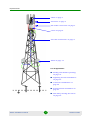
“GPS” on page 2
“Antenna” on page 3
“RF Cable Connection” on page 4
“ODU” on page 8
“IF Cable Connection” on page 9
“BTS” on page 15
List of Appendixes:
“Sealing and Weather-proofing”
on page 18
“Lightning Arrestor Installation”
on page 22
“Connector Installation” on
page 26
“Transportation Guidelines” on
page 34
“ATP Sweep Testing Procedure”
on page 36
4Motion Installation Procedure
vii
Reference Guide
Introduction
1.
Introduction
This handbook provides general guideline for the physical installation and
inspection of a basic site. The handbook describes the requirements from a proper
installation.
It is assumed that professional radio and site surveys have been conducted. This
is highly recommended in order to avoid radio, space, electricity, and other
environmental issues.
This handbook is intended for professional installers.
Referenced manuals:
4Motion Installation Manual - downloadable from the web.
2.
General Prerequisites
For best installation results, installers must first complete the official Alvarion’s
CAIT or CASS course training.
3.
Site Construction and Inspection
Make sure that the site can be accessed by Alvarion employees/sub-contractors
and their equipment.
Make sure that there is safe entrance, exit, and parking available.
When building a site from scratch, prepare reports after each construction phase.
When the site is ready for installation, make sure you have at least one of the
following reports available for inspection:
Civil engineering report: includes information on building strength, approach
roads, aviation safety, water, sewage, electricity lines etc. Check that the
report was approved by a civil engineer before using the site.
As built report: including tests of tower/pole/mast strength and approval to
add the extra equipment in the required height.
Soil measurements report: with soil resistance per meter used for calculating
the grounding resistance.
Electrician report: including the approval of the electrician for the grounding
systems. Verify that the resistance is under 10Ω.
4Motion Installation Procedure
1
Reference Guide
Installation
GPS
Operator report: including all the information on the site infrastructure and
approvals.
When installing on an existing infrastructure (tower, pole, mast) with existing
grounding, obtain the documentation for inspection before beginning the
installation.
4.
Installation
4.1
GPS
4.1.1
Requirements
Before starting the GPS installation, make sure you have the following:
Deployment instructions detailing the type and positioning of the GPS
(obtained from the Project Manager)
GPS - verify that you have the correct GPS types according to the deployment
instructions
Mounting kit
Grounding cables with termination according to connection type
Lightning surge arrestor
Cat.5E Ethernet cable
Installation tools and materials, including means for installing the GPS
(Phillips screwdriver, tools for connector installation (see Appendix C), etc.)
Sealing materials (see Appendix A).
4.1.2
Installation
1
Install the GPS in the locations detailed in the deployment instructions.
2
Install the GPS and connect the GPS cable to the BTS according to the
instructions in the 4Motion Installation Manual.
3
Ground the GPS according to the instructions in the 4Motion Installation
Manual.
4Motion Installation Procedure
2
Reference Guide
Installation
Antenna
4
Connect the GPS to the lightning surge arrestor as instructed in the
documentation provided by the manufacturer with the lighting arrestor. If no
instructions are provided, see Appendix B.
5
Seal the connector according to Appendix A “Sealing and Weather-proofing” on
page 18.
4.1.3
Inspection
1
Check that the GPS is oriented parallel to the horizon.
2
Check that there are no obstacles, such as vegetation and buildings, blocking
the view of the GPS antenna.
3
Check that all nuts and bolts are firmly connected and are not loose.
4
Check that the GPS is properly grounded.
5
Check that the GPS is properly protected by a lightning arrestor.
4.2
Antenna
4.2.1
Requirements
Make sure that you have the following:
Radio Network Planning document - make sure you have the most recent
version with the correct azimuth, tilt, and height.
The documentation provided by the antenna manufacturer
Antennas, including mounting kit (fixed and adjustable downtilt).
Installation tools: digital compass, binoculars, GPS, inclinometer.
4.2.2
Installation
1
Check that there are no obstacles, such as vegetation and buildings, blocking
the planned azimuth of the antenna.
2
Install the antenna according to the documentation provided by the antenna
manufacturer.
3
Check the azimuth and tilt of the antenna against the Radio Network Planning
document:
»
Check the azimuth from the center of the antenna
4Motion Installation Procedure
3
Reference Guide
Installation
RF Cable Connection
»
If more than one antenna are used, check the azimuth from the exact
center point between the antennas
»
4.2.3
Use an inclinometer to check the tilt.
Inspection
1
Check that the antennas are installed according to the Radio Network
Planning document.
2
Verify that there are no obstacles, such as vegetation and buildings, blocking
the planned azimuth of the antenna.
4.3
RF Cable Connection
4.3.1
Requirements
Before starting the RF cable installation make sure you have the following:
Proper RF cable in terms of length and condition
The right installation tools
Sealing materials (see Appendix A)
4.3.2
RF Cable Installation
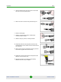
1
2
Connect the RF cable to the antenna port.
»
Apply torque of 1.7 [N*m]/15.00 [Lbf*in].
»
Do not over-tighten so as not to damage the connector.
»
Check that the connector is firmly closed.
Seal the connector according to Appendix A “Sealing and Weather-proofing” on
page 18.
3
Connect the RF cable to the ODU port.
»
Make sure you connect the right ODU port to the correct polarization
antenna element.
»
Apply torque of 1.7 [N*m]/15.00 [Lbf*in].
»
Do not over-tighten so as not to damage the connector.
»
Check that the connector is firmly closed.
4Motion Installation Procedure
4
Reference Guide
Installation
RF Cable Connection
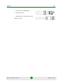
Figure 1: Antenna RF Cable Connection to 2x2/4x2 ODU
4Motion Installation Procedure
5
Reference Guide
Installation
RF Cable Connection
Antenna 1
Dual-slant
-45 +45
Antenna 2
Dual-slant
-45 +45
ANT2
ANT1
4x2 AU-ODU
ANT1
ANT2
Rx
RxTx
RxTx
Rx
To ODU IF1
To ODU IF2
AU
RxTx
To ODU IF3
To ODU IF4
Rx
RxTx
Rx
Figure 2: Antenna Connection Diagram (4x2 ODU)
4Motion Installation Procedure
6
Reference Guide
Installation
RF Cable Connection
Antenna 1
Dual-slant
-45 +45
Antenna 2
Dual-slant
ANT2
-45 +45
ANT2
ANT1
ANT1
2x2 AU-ODU
2x2 AU-ODU
RxTx
RxTx
RxTx
RxTx
To ODU IF1
AU
To ODU IF3
To ODU IF3
RxTx
Rx
RxTx
Rx
Figure 3: Antenna Connection Diagram (2x2 ODU)
4Motion Installation Procedure
7
Reference Guide
Installation
ODU
4
Seal the connector according to Appendix A “Sealing and Weather-proofing” on
page 18.
5
Fix the RF cable onto the pole using Velcro® wide adjustable straps.
»
If possible, use additional straps to route the cable such that water can
accumulate on the cable bends, away from the unit.
»
When routing the cable, do not exceed the minimum bending radius in the
cable specifications.
4.3.3
Inspection
1
Check that all the connectors are firmly connected and are not loose.
2
Check that all connectors are properly sealed, according to “Sealing and
Weather-proofing” on page 18.
3
Check that water can accumulate on the cable bends, away from the unit.
4
Check that the cable passes a pull test according to the connector’s
specifications.
4.4
ODU
4.4.1
Requirements
Make sure that you have the following:
Deployment instructions detailing the type and positioning of each ODU
(obtained from the Project Manager)
ODUs - verify that you have the correct ODU types and sub-bands according
to the ODU deployment instructions
Mounting kits (for one, two, or three ODUs, and also for round, or L-shaped
poles/masts)
Grounding cables with terminations according to connection type
Installation tools and materials, including means for installing the ODU (a
harness for lifting the ODUs, wrenches, etc.)
Sealing materials (see Appendix A)
Anti oxidant protective grease
4Motion Installation Procedure
8
Reference Guide
Installation
4.4.2
IF Cable Connection
ODU Installation
1
Apply protective grease on all nuts, bolts, and lugs for additional protection
against corrosion.
2
Install the ODUs in the locations detailed in the deployment instructions.
3
Install each ODU according to the instructions in the 4Motion Installation
Manual.
4
Ground each ODU according to the instructions in the 4Motion Installation
Manual.
4.4.3
Inspection
1
Check that all nuts and bolts are firmly connected and are not loose.
2
Check that the ODU is not blocking the antenna as this might cause
reflections.
3
Check that the distance between the ODU and other components is sufficient
to allow easy and effective connection and sealing of the IF and RF cables.
4
Check that all nuts and bolts are properly greased.
4.5
IF Cable Connection
4.5.1
Requirements
Before starting the IF cable installation make sure you have the following:
Ready-made IF cables in the correct lengths and requirements (see Table 1).
Use only ready-made LMR-400 double shielded cables.
Table 1: IF Cable Requirements
Item
Description
Screening Effectiveness
90 dB minimum in the 10-300 MHz band.
IF cable Impedance
50 Ohm
Maximum IF cable Attenuation
10 dB @ 240 MHz
7.5 dB @ 140 MHz
8 dB @ 64 MHz
Maximum IF cable DC Resistance
1.5 Ohm
Maximum IF cable Return Loss
20 dB in the 10-300 MHz band
4Motion Installation Procedure
9
Reference Guide
Installation
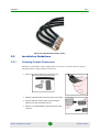
IF Cable Connection
The right installation tools
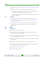
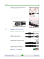
Grounding kits for LMR 400 IF cables.
Figure 4: LMR 400 Grounding Kit
The installation instructions for the grounding kits and the required tools
Sealing materials (see Appendix A).
4.5.2
IF Cable Installation
1
Measure the exact length of the IF cable to be used taking into account the
height at which the ODU is installed and the distance to the base band unit
(whether indoor AU card, or NAU/SAU/DAU). In case of a macro indoor unit,
take into account also the distance to the shelter and inside the shelter to the
rack.
2
Test the cable before connecting it to the ODU and base band units using
designated equipment, such as a reflectometer and a strength field meter, to
assure proper cable assembly. Verify that the return loss is less than 20 dB.
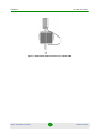
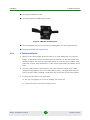
3
Connect the IF cable to the ODU port.
»
Do not over-tighten so as not to damage the connector
»
Check that the connector is firmly closed.
4Motion Installation Procedure
10
Reference Guide
Installation
IF Cable Connection
Figure 5: Connecting the IF Cable
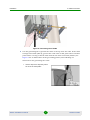
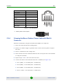
4
Use the grounding kit to ground the cable at the top near the ODU. If the cable
is longer than 60m (200 ft), ground the cable also at mid point and at another
point before curving of the IF cable towards the base band unit/shelter (see
Figure 6 for an illustration of the grounding points). The following are
instructions for grounding the cable.
1
Use the strip tool to strip away about
40 mm of the outer plastic.
4Motion Installation Procedure
11
Reference Guide
Installation
IF Cable Connection
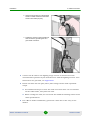
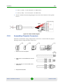
4
2
Clamp the grounding kit on the stripped
section of cable. Ensure that the metal
sections are sealed properly.
3
Tighten the screws on the grounding kit
and connect the grounding wire to a
good earth connection.
Connect the IF cable to the lighting surge arrestor as instructed in the
documentation provided by the manufacturer with the lighting arrestor. If no
instructions are provided, see Appendix B.
5
Fix the IF cable onto the pole/tower/mast using Velcro® wide adjustable
straps.
»
Use additional straps to route the cable such that water can accumulate
on the cable bends, away from the unit.
»
When routing the cable, do not exceed the minimum bending radius in the
cable specifications.
6
For a Macro Indoor installation, ground the cable also at the entry to the
shelter:
4Motion Installation Procedure
12
Reference Guide
Installation
IF Cable Connection
»
On the exterior side to the exterior grounding system
»
On the interior side to the interior grounding system.
Figure 6: IF Cable Grounding Points: Macro Outdoor (Left) and Macro Indoor (Right)
7
Mark the IF cables as follows:
»
Use different tape colors for different sectors.
»
Attach one to four tapes to each cable according to the connection number.
For example: Attach one red tape on both ends of the IF1 cable, two red
tapes on both ends of the IF2 cable, and so on. See Figure 7.
4Motion Installation Procedure
13
Reference Guide
Installation
IF Cable Connection
IF-1 Cable
IF-2 Cable
IF-4 Cable
4 marking tapes for
IF-4 connection
IF-3 Cable
Figure 7: Example of IF Cables Color Coding
8
9
Connect the IF cable to the base band unit.
»
Make sure that the cables are connected according to the marking.
»
Do not over-tighten so as not to damage the connector.
»
Check that the connector is firmly closed.
Seal the outdoor connectors and grounding points according to Appendix A
“Sealing and Weather-proofing” on page 18.
4Motion Installation Procedure
14
Reference Guide
Installation
4.5.3
BTS
Inspection
1
2
Check that all connectors are firmly connected and are not loose.
Check that all connectors are properly sealed, according to “Sealing and
Weather-proofing” on page 18.
3
Check that water can accumulate on the cable bends, away from the unit.
4
Check that the IF cables are grounded to the tower/pole/mast at the top and
bottom of the tower/pole/mast.
5
If the tower is taller than 60m (200 ft), check that the cable is grounded also at
midpoint.
6
For a structure that has a coaxial cable entrance plate, check that the
entrance plate is fixed to both the interior and the exterior of the structure’s
ground ring.
7
Check that the coaxial shield is also fixed to the exterior and interior of the
metallic entrance plate.
8
Check that the coaxial cable is protected by a lightning surge arrestor.
9
Check that the lightning arrestor is fixed to the exterior ground electrode
system.
10 Verify that the IF cables have passed the return loss test and that the return
loss is less than 20 dB.
4.6
BTS
4.6.1
Requirements
Before starting the BTS installation, make sure you have the following:
Deployment instructions detailing the type and positioning of each BTS
(obtained from the Project Manager)
BTSs - verify that you have the correct BTS types according to the BTS
deployment instructions
Mounting kits for outdoor BTSs (according to installation type)
Grounding cables with terminations according to connection type
Installation tools and materials, including means for installing the BTS (a
harness for lifting the BTS, screwdrivers, wrenches, etc.)
4Motion Installation Procedure
15
Reference Guide
Installation
4.6.2
BTS
Installation
1
Apply protective grease on all outdoor nuts, bolts, and lugs for additional
protection against corrosion.
2
Install the BTS in the locations detailed in the deployment instructions.
3
Install each BTS according to the instructions in the 4Motion Installation
Manual.
4
To prepare a power cable, follow the instructions in Section C.2.4. See also the
4Motion Installation Manual.
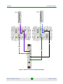
5
Connect the power cable to the power supply.
a
Connect the black wires to the RTN connector(s) on the power supply.
b
Connect the red wires to the +48V connector(s) on the power supply.
Figure 8: Connection to Power Supply
6
To connect the power cable to a circuit breaker, follow the block diagram
example in Figure 9.
7
Ground each BTS according to the instructions in the 4Motion Installation
Manual.
4Motion Installation Procedure
16
Reference Guide
Installation
BTS
Figure 9: Connecting to a Circuit Breaker
4.6.3
Inspection
1
Check that all nuts and bolts are firmly connected and are not loose.
2
Check that all nuts and bolts are properly greased.
3
Measure the return loss of the IF cables. Check that it is less than 20 dB.
4Motion Installation Procedure
17
Reference Guide
Installation
BTS
Appendix A: Sealing and Weather-proofing
A.1
Requirements
All sealings and weather-proofing must comply with the IP-67 standard.
Seal all outdoor connectors that are not supplied with sealing glands to protect
against rain and moisture.
Seal all grounding points on the IF cables.
Use high quality sealing material such as Scotchfil™ Electrical Insulation
Putty from 3M (or equivalent) over-wrapped with a UV resistant outdoor rated
tape (e.g. Super 33+ or Super 88 vinyl Electrical Tape).
Use high quality cold shrink sleeves to seal connectors.
Figure 10: Sealing Materials
A.2
Sealing Instructions
4Motion Installation Procedure
18
Reference Guide
Installation
A.2.1
BTS
Connectors
1
Cut the cold shrink sleeve to size. Take into
account the size of the unit’s connector and
additional 2.5 cm (0.5 in.).
2
Slide the cold shrink sleeve onto the cable
before connecting the cable.
3
Connect the cable.
4
Attach the mastic tape (Scotchfil™
Electrical Insulation Putty) and wrap it
around the connector butting up against the
connector. Do not over stretch.
5
Squeeze to tighten the mastic sealer. Make
sure there are no air bubbles.
6
Slide the cold shrink sleeve on top of the
connector. Make sure that the sleeve
covers both cable connector and unit
connector.
7
Pull the cord slowly to shrink the sleeve.
4Motion Installation Procedure
19
Reference Guide
Installation
A.2.2
BTS
Angled Connectors
1
Cut the cold shrink sleeve to size. Take into
account the size of the unit’s connector.
2
Slide the cold shrink sleeve onto the cable
before connecting the cable.
3
Connect the cable.
4
Attach the mastic tape (Scotchfil™
Electrical Insulation Putty) and wrap it
around the connector butting up against the
connector. Do not over stretch.
5
Squeeze to tighten the mastic sealer. Make
sure there are no air bubbles.
6
Slide the cold shrink sleeve on top of the
connector. Make sure that the sleeve
covers both cable connector and unit
connector.
7
Pull the cord slowly to shrink the sleeve.
4Motion Installation Procedure
20
Reference Guide
Installation
A.2.3
BTS
Cable Grounding Points
Use mastic band and vinyl tape to seal and weather-proof all grounding points:
1
Ground the cable
according to the
instructions provided with
the grounding kit.
2
Apply some mastic
(Scotchfil™ Electrical
Insulation Putty, or
equivalent) to the
grounding cable
3
Attach the mastic band
and wrap it around the
grounding point. Do not
over stretch.
4
Squeeze to tighten the
mastic band. Make sure
there are no air bubbles
5
Weather-proof the
connection using the vinyl
tape.
6
Apply a second wrap from
the top down (without
cutting the tape). Stretch
the vinyl tape tightly.
Wrap the connection
starting from the bottom
up. Begin about 2.5 cm
(1”) below the mastic band.
Do not overtighten to avoid
the mastic from squeezing
through.
4Motion Installation Procedure
21
Do the last wrap from
bottom up to allow water to
flow off.
Reference Guide
Installation
BTS
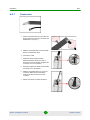
Appendix B: Lightning Arrestor Installation
B.1
Requirements
Install a lightning arrestor on each GPS and electronic equipment, and at the
building entrance. Use a PolyPhaser® lightning arrestors according to the
frequency of the protected equipment.
Installation tools
Dow Corning RTV-3145 adhesive/sealant or equivalent thixotropic silicone
Figure 11: Dow Corning RTV-3145 Adhesive/Sealer
Additional sealing materials (see Appendix A)
Figure 12: Example of PolyPhaser Lightning Arrestor
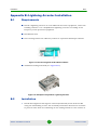
B.2
Installation
1
Install the Polyphaser 90-degrees oriented (horizontal) on the feed bracket
using the self-locking screws. The assembly orientation direction is essential
to prevent water from accumulating on the sealing interfaces. The surface of
4Motion Installation Procedure
22
Reference Guide
Installation
BTS
the bracket must be clean metal with no contamination, in order to allow solid
electrical contact to the Polyphaser.
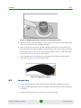
Figure 13: Polyphaser Correct and Wrong Installations
2
Cut the IDU/ODU cables to length, install RF connectors, and attach to the
Polyphaser.
3
Pay special attention to ensure that the ODU cable is supported within 0.6m (2
ft.) of the Polyphasers. The cable must not be run in a manner that unduly
stresses the mechanical interface of the Polyphaser to the ODU connector even
though the bracket in itself provides rigidity and strain relief.
4
Apply a layer of RTV around the RF connector to fill the groove by using nozzle.
This operation will prevent water penetration between the connector and the
case. Wait 2-4 hours for the silicone to cure.
4Motion Installation Procedure
23
Reference Guide
Installation
BTS
Figure 14: Applying Silicone to the Groove of the RF Connector
5
Apply the mastic tape extending at least 50 mm (2”) onto the cable sheath and
also cover the connectors bolt body interface.
6
Wrap a vinyl tape to provide UV and abrasion protection for the mastic tape.
The vinyl tape must extend 50mm (2”) beyond the end of the mastic tape along
the sheath of the cable. Do not stretch the final few turns to avoid wind-back.
Firmly smooth over to ensure a good bond.
7
The wrapping direction should be in parallel to the connector bolt closing
direction. See Figure 15 for the final result.
Figure 15: Polyphaser Sealing
B.3
Inspection
1
Check that all external radio units are protected with a lightning arrestor.
2
Check that the lightning arrestor is suitable for the frequency of the equipment
it protects.
3
Check that all the protected units are suitably grounded.
4Motion Installation Procedure
24
Reference Guide
Installation
BTS
4
Check that all lightning arrestors are suitably grounded.
5
Check that all the connections on the lightning arrestors are properly sealed.
4Motion Installation Procedure
25
Reference Guide
Installation
BTS
Appendix C: Connector Installation
C.1
Requirements
Use PPC compression connectors for coaxial cables. Consult with the project
manager before using other connectors.
Use only proper installation tools for installing connectors:
Crimp tool
Cutting tool
Strip tool
Compression tool
Deburring tool
This section provides instructions for installing the following types of connectors:
“Crimping Coaxial Connectors” on page 27
“Assembling Compression Connectors” on page 29
“Crimping RJ-45 Connectors” on page 30
“Crimping the Macro Outdoor Power Cable with Mini-fit Connector” on page 31
“Assembling Threaded Connectors” on page 32
4Motion Installation Procedure
26
Reference Guide
Installation
BTS
Figure 16: Assembled Connector (TNC)
C.2
Installation Guidelines
C.2.1
Crimping Coaxial Connectors
Alvarion recommends using compression connectors. Consult with the project
manager before using crimped connectors.
1
Flush cut the cable squarely using the cutting tool.
2
Slide the cold shrink sleeve and crimp ring onto the cable.
3
Strip the cable-end using a strip tool by inserting the
cable into one end and rotating the tool.
4
Remove any residual dielectric material from the center
conductor.
4Motion Installation Procedure
27
Reference Guide
Installation
BTS
5
Insert the cable into the other end of the tool and rotate
the tool to remove the plastic jacket
6
Deburr the center conductor using the deburring tool
7
Flare the braid slightly.
8
Push the connector body onto the cable until the
connector snaps into place.
9
Slide the crimp ring forward, creasing the braid.
10 Temporarily slide the crimp ring back and remove the
connector body from the cable to trim the excess braid at
the crease line.
11 Remount the connector and slide the crimp ring forward
until it butts up against the connector body.
12 Position the crimp tool with the dies directly behind and
adjacent to the connector body.
13 Crimp the connector. The crimp tool automatically
releases when the crimp is complete.
4Motion Installation Procedure
28
Reference Guide
Installation
BTS
14 Position the heat shrink sleeve as far forward on the
connector body as possible, without interfering with the
coupling nut.
15 Use a heat gun to form a weather tight seal.
C.2.2
Assembling Compression Connectors
Alvarion recommends using PPC compression connectors.
1
Flush cut the cable squarely using the cutting tool.
2
Strip the cable-end using the strip tool by inserting the
cable into one end and rotating the tool.
3
Remove any residual dielectric material from the center
conductor.
4
Insert the cable into the other end of the tool and rotate
the tool to remove the plastic jacket.
5
Deburr the center conductor using the deburring tool
4Motion Installation Procedure
29
Reference Guide
Installation
C.2.3
BTS
6
Push the connector body onto the cable until the
connector snaps into place.
7
Position cable with the connector in the compression tool
and squeeze the tool’s handle.
Crimping RJ-45 Connectors
1
Thread the RJ-45 plastic cover on the cable.
2
Reveal 5 cm of outer sleeve.
3
Reveal 4 cm of the inner sleeve.
4
Release all wires and arrange them in order.
5
Cut the wires to 1 cm length each.
6
Insert the wires into the connector.
7
Press the connector using a crimp tool.
8
Solder the shield drain wire to the connector.
Refer to Figure 17 for Pin assignment.
4Motion Installation Procedure
30
Reference Guide
Installation
BTS
Wire color
Pin
Orange/white
1
Orange
2
Brown/white
3
Brown
4
Blue
5
Blue/white
6
Green
7
Green/white
8
Figure 17: Pin Assignment
9
C.2.4
Push the plastic cover into place.
Crimping the Macro Outdoor Power Cable with Mini-fit
Connector
Alvarion recommends using the Pressmaster® DRB-0115 crimp tool.
1
Insert the cable through the sealing gland.
2
Remove as small a length as possible of the cable's external jacket to expose
the wires.
3
Insert a terminal into the crimper slot.
4
Insert the wire into the terminal within the slot and squeeze the tool's handles
to crimp the terminal.
5
Repeat steps 3 and 4 for each of the six wires.
6
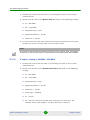
Connect the wires to the mini-fit connector as follows (see Figure 18):
»
Pin 1 (RTN) - to 1A: Black (min. 16 AWG wire)
»
Pin 2 (RTN) - to 2A: Black (min. 16 AWG wire)
»
Pin 3 (RTN) - to 3A: Black (min. 16 AWG wire)
»
Pin 4 (+48V) - to 4A: Red (min. 16 AWG wire)
4Motion Installation Procedure
31
Reference Guide
Installation
BTS
7
»
Pin 5 (+48V) - to 5A: Red (min. 16 AWG wire)
»
Pin 6 (+48V) - to 6A: Red (min. 16 AWG wire)
Attach suitable terminal rings (lugs) to the side that connects to the power
source.
Figure 18: Power Cable Diagram
C.2.5
Assembling Threaded Connectors
Alvarion recommends using compression connectors. Consult with the project
manager before using threaded connectors.
1
Remove 8.5 mm of the jacket.
2
Slide screw "A" and assemble "B" onto the
cable.
3
Slide assembly "C" onto the cable until it
reaches “B”.
4
Stripe braid backwards.
4Motion Installation Procedure
32
Reference Guide
Installation
BTS
5
Strip 6 mm of the cable-dialectric
6
Chamfer center pin.
7
Assemble body "D" and tighten screw "A".
Apply torque 8 Nm.
4Motion Installation Procedure
33
Reference Guide
Installation
BTS
Appendix D: Transportation Guidelines
The following are the storage and transportation guidelines for the handling of
Alvarion products.
D.1
Packing
All goods must be packed using original cartons only
All cartons must have the appropriate symbols printed ("This side up",
“Fragile”, etc.)
Cartons must be arranged with all labels facing outwards.
Cartons must be packed such that the heavier and larger cartons are at the
bottom.
Maximum height for pallets: 1.60m
D.2
Warehouse
Goods must be stored in a closed and secured warehouse
The warehouse must be waterproofed against rain
The warehouse must comply with local safety regulations
The warehouse must have a full and comprehensive insurance policy
All goods must be stored on wooden pallets
Stacking of pallets is not permitted
D.3
Transport
Vehicles used for transporting must be:
»
Big enough to carry all needed
»
Closed/sealed (rain-protected)
»
Dry
4Motion Installation Procedure
34
Reference Guide
Installation
BTS
»
Not used for transporting animals, food, chemicals, or liquids
Transport will be insured in accordance with the goods being shipped
Suitable loading/offloading equipment (i.e. forklifts) must be used.
»
Forklift drivers must have required training and permits
Maximum height of pallets during transit must not exceed 1.60m
The vehicle/transportation process must comply with local safety regulations.
D.4
On-site Storage
If during installation there is a need to store the equipment on site, a waterproof
shelter is mandatory.
4Motion Installation Procedure
35
Reference Guide
ATP Sweep Testing Procedure
Appendix E: ATP Sweep Testing Procedure
This appendix applies to all RF and IF feedlines and connectors, antennas, surge
suppressors, and Polyphasers. Repeated testing has shown that equipment failure
is often the result of improperly installed and sealed connectors, used in
conjunction with the LMR400 coaxial cable.
All the cables and connectors must be tested for proper operation before
installation. The tests check the following:
Cable loss
Connector integrity
Cable imperfections
Antenna bandwidth
Antenna Center Frequency
IMPORTANT
All components must be tested individually on the ground to ensure that only working
components are being installed.
All components must be tested on the ground as a complete system before any tower work
begins.
The tests described in this appendix:
Identify cables with bad connectors or workmanship in the assembly of the
connector-to-cable junction.
Confirm that new cables are made correctly and tested fully before the new
cables are weatherproof sealed.
E.1
Component Operation
The WiMAX radio system consists of five main components, with a coaxial cable
used to interconnect these components:
“Indoor Radio Unit” on page 37
“Outdoor Radio Unit” on page 37
4Motion Installation Procedure
36
Reference Guide
ATP Sweep Testing Procedure
“Inter-connecting IF Cables and Power Cables” on page 37
“Lightning Arrestor” on page 38
“WiMAX Sector Antennas” on page 38
There are two independent systems at each WiMAX site:
WiMAX Radio Site Access Point
Microwave Radio Backhaul system to a central high speed internet Gateway.
E.1.1
Indoor Radio Unit
The Indoor Radio Unit (IDU) has the following sub-sections:
Power supply
Baseband multiplex transmitter and intermediate frequency upconverter
Baseband de-multiplexer receiver and intermediate frequency decoder
E.1.2
Outdoor Radio Unit
The Outdoor Radio Unit (ODU) has separate cables for the transmitter IF (IDU to
ODU) and receiver IF (ODU to IDU). The DC power for the ODU is carried on both
cables from the IDU power supply to the voltage regulator on the ODU.
E.1.3
Inter-connecting IF Cables and Power Cables
The IF cable carries the intermediate IF power (100 MHz to 250 MHz) and signals
from the IDU to the ODU:
IF transmitter signal from the IDU to the ODU
IF receiver signal from the ODU to the IDU
Power from the IDU to the ODU
Confirmation that the connectors can carry the IF signal and the DC power
between the IDU and the ODU
4Motion Installation Procedure
37
Reference Guide
ATP Sweep Testing Procedure
IMPORTANT
Because of the currents involved, and the minimum amount of cable current capacity,
there must be no defect in the cable or foil shield.
E.1.4
Lightning Arrestor
1
Sweep the Lightning Arrestor at the IF frequency for proper Return Loss (RL).
2
Ensure that the DC resistance for carrying the power from the IDU to the ODU
is correct.
E.1.5
WiMAX Sector Antennas
1
Test the WiMAX Sector Antennas to ensure that the frequency band of the
Antenna is correct.
2
Ensure that there is a good 50 Ohm match between the antenna and the
coaxial connector at the back of the antenna.
3
E.2
Perform a Return Loss Line Sweep for each antenna on the site.
Reflectometer
Use a reflectometer to test the cables before connecting them to the radio units.
Calibrate the tool before each frequency change. It is recommended to sweep all of
the cables for each calibration setting, rather than to do all sweeps for one cable
before moving on to the next cable.
Follow the instructions provided with the reflectometer in order to operate and
calibrate it.
CAUTION
Handle the phase stable cable and the open-short-load calibration tee with care. Dropping them
may cause them damage.Ensure that any cable being tested has no power from the IDU before
attaching the calibration tee from the reflectometer. Any amount of DC power or radio energy will
destroy the calibrated load part of the tee, and the calibrated short will damage the IDU power
supply if that section is connected while under power.
E.3
Equipment Sweep Tests
Use the supplied Installation Manual to wire up the cables and hardware, and for
mounting both the IDU and the ODU.
4Motion Installation Procedure
38
Reference Guide
ATP Sweep Testing Procedure
Pre-measure the LMR400 RF cables needed to connect the IDU to the ODU and
cut to the required length.
Use only PPC connectors and an LMR400 cable for this purpose.
When making the connectors, do not nick or cut the foil shield or the strands of
ground wire that are part of the shield.
IMPORTANT
The loss of even a small part of the shield will cause a failure of the Radio ODU .
E.3.1
Cables
The cables used at the IF and RF frequencies must be installed properly, and the
shields must be fully intact. The test setups and sweeps are used to confirm that
the cables are properly made and that the braid of the cable shields is not cut or
nicked.
NOTE
All cables must be labeled according to the Alvarion labeling standards:
Access point cables: IF and RF cables
Microwave backhaul cables
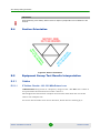
E.3.1.1
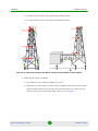
Cable Nomenclature
The diagram below demonstrates location designation and labeling for sector
feedlines when multiple paths are installed on a tower.
1
Mark the first sector installation at, or nearest to 0 (zero) degrees with one red
ring of tape (R1).
2
Mark each additional sector installation in clockwise order with an additional
red ring of tape (R2, R3, etc.)
3
If a specific antenna carries more than one Radio Unit, requiring multiple IF
coaxial cables installed, mark each additional coaxial cable with a blue ring of
tape.
4
The third sector cables must be marked in green rings of tape, with the first
cable marked with one green ring of tape, and each additional cable with an
additional green ring of tape
4Motion Installation Procedure
39
Reference Guide
ATP Sweep Testing Procedure
IMPORTANT
There can never be more than four cables per antenna.
Figure 19: Designation and Labeling for Microwave Feed Lines
E.3.1.2
Jumper Cables
Perform the same tests that are performed for the long IF cables for jumper cables
from the IDU to the Polyphaser lightning arrestors.
E.3.1.3
IF Cables - Sweep 1: 100 MHz - 250 MHz
1
Calibrate the analysis tool.
2
Perform this test for the first time by connecting the cable to the 50 Ohm
calibrated load.
3
Sweep each IF cable in Return Loss (RL) mode with the following settings:
»
F1 = 100 MHz
»
F2 = 250 MHz
»
Amplitude Top = 0 dB
»
Amplitude Bottom = -60 dB
»
Limit Line = -20 dB
4Motion Installation Procedure
40
Reference Guide
ATP Sweep Testing Procedure
4
To ensure that the cable and connectors function properly for the IF signal,
perform the test for each IF cable and record the results.
NOTE
This frequency sweep shows how the cable reacts to the IF signal.
5
To discover a loss of the IF signal as it passes through the IF cable, perform
the same test into a calibrated short.
6
E.3.1.4
Perform the test for each IF cable and record the results.
IF cables - Sweep 2: 100 MHz - 250 MHz
1
Perform this test for the first time by connecting the cable to the 50 Ohm
calibrated load.
2
Sweep each IF cable in the Distance to Fault (DTF) mode at the following
settings:
»
F1 = 100 MHz
»
F2 = 250 MHz
»
Amplitude Top = 0 dB
»
Amplitude Bottom = -60 dB
»
Limit Line = -20 dB
»
Cable Type = LMR400
»
D1 = 0 feet
»
D2 = xxx feet (xxx is the length of the cable plus an extra 50%. For
example, if the cable length is 100 feet, then xxx is 150 feet.
3
To ensure that the cable and connectors function properly for the IF signal,
perform the test for each IF cable and record the results.
4
To discover the loss of the IF signal as it passes through the IF cable, perform
the same test into a calibrated short.
5
E.3.1.5
Perform the test for each IF cable and record the results.
IF cables - Sweep 3: 800 MHz - 1000 MHz
1
Calibrate the analysis tool.
4Motion Installation Procedure
41
Reference Guide
ATP Sweep Testing Procedure
2
Perform this test for the first time by connecting the cable to the 50 Ohm
calibrated load.
3
4
Sweep each IF cable in the Return Loss (RL) mode at the following settings:
»
F1 = 800 MHz
»
F2 = 1000 MHz
»
Amplitude Top = 0 dB
»
Amplitude Bottom = -60 dB
»
Limit Line = -20 dB
To ensure that the cable and connectors function properly for the DC power,
perform the test for each IF cable and record the results.
NOTE
This frequency sweep shows how the cable and connectors react to the DC signal. If the shield is
damaged in any way, this high frequency sweep will discover the problem before cable installation.
E.3.1.6
IF cables - Sweep 4: 800 MHz - 1000 MHz
1
Perform this test for the first time by connecting the cable to the 50 Ohm
calibrated load.
2
Sweep each IF cable in the Distance To Fault (DTF) mode at the following
settings:
»
F1 = 800 MHz
»
F2 = 1000 MHz
»
Amplitude Top = 0 dB
»
Amplitude Bottom = -60 dB
»
Limit Line = -20 dB
»
Cable Type = LMR400
»
D1 = 0 Feet
»
D2 = xxx feet, xxx is the length of the cable plus an extra 50%. For
example, if the cable length is 100 feet, then xxx is 150 feet.)
4Motion Installation Procedure
42
Reference Guide
ATP Sweep Testing Procedure
3
To ensure that the cable and connectors function properly for the DC power,
perform the test for each IF cable and record the results.
NOTE
This frequency sweep shows how the connectors react to the DC signal.
E.3.1.7
RF cables - Sweep 1: Bandwidth According to the ODU
1
Calibrate the analysis tool.
2
Connect the analysis tool to one end of the cable and the 50 Ohm precision
load to the other end.
3
Sweep each IF cable in Return Loss (RL) mode at the following settings:
»
F1
◊ For ODUs with a 2300 MHz bandwidth, F1= 2200 MHz
◊ For ODUs with a 2500 MHz bandwidth, F1= 2400 MHz
◊ For ODUs with a 3500 MHz bandwidth, F1= 3400 MHz
»
F2
◊ For ODUs with a 2300 MHz bandwidth, F2= 2400 MHz
◊ For ODUs with a 2500 MHz bandwidth, F2= 2600 MHz
◊ For ODUs with a 3500 MHz bandwidth, F2= 3600 MHz
4
»
Amplitude Top = 0 dB
»
Amplitude Bottom = -60 dB
»
Limit Line = -20 dB
Perform the test for each RF cable and record the results.
NOTE
This frequency sweep shows how the cable and connectors react to the Microwave signal. If the
shield is damaged in any way, this high frequency sweep will discover the problem before cable
installation.
4Motion Installation Procedure
43
Reference Guide
ATP Sweep Testing Procedure
5
To record signal loss of the RF cable at the Microwave frequency, substitute
the calibrated short for the 50 Ohm load, and run the RL sweep a second time.
6
E.3.1.8
Perform the test for each RF cable and record the results.
RF cables - Sweep 2: Bandwidth According to the ODU
1
Calibrate the analysis tool.
2
Connect the analysis tool to one end of the cable and the 50 Ohm precision
load to the other end.
3
Sweep each IF cable in Distance To fault (DTF) mode at the following settings:
»
F1
◊ For ODUs with a 2300 MHz bandwidth, F1= 2200 MHz
◊ For ODUs with a 2500 MHz bandwidth, F1= 2400 MHz
◊ For ODUs with a 3500 MHz bandwidth, F1= 3400 MHz
»
F2
◊ For ODUs with a 2300 MHz bandwidth, F2= 2400 MHz
◊ For ODUs with a 2500 MHz bandwidth, F2= 2600 MHz
◊ For ODUs with a 3500 MHz bandwidth, F2= 3600 MHz
4
»
Amplitude Top = 0 dB
»
Amplitude Bottom = -60 dB
»
Limit Line = -20 dB
Perform the test for each RF cable and record the results.
E.3.2
Lightning Arrestor
E.3.2.1
100 MHz - 250 MHz Sweep
1
2
Calibrate the analysis tool.
Put the 50 ohm load at the antenna side of the Lightning Protector and the
analysis tool phase stable cable on the equipment side of the Lightning
Protector.
4Motion Installation Procedure
44
Reference Guide
ATP Sweep Testing Procedure
3
Sweep each Lightning Protector in Return Loss (RL) mode at the following
settings:
4
»
F1=100 MHz
»
F2=250 MHz
»
Amplitude Top = 0 dB
»
Amplitude Bottom = -60 dB
»
Limit Line = -25 dB
Perform this test for each Lightning Protector cable and record the results.
NOTE
This frequency sweep shows how the Lightning Protector reacts to the IF signal.
E.3.3
Microwave Antennas
All working antennas exhibit a region in the frequency band in which there is an
increase capabilities (a good match with 50 Ohm) and a decrease in their
capabilities (no match with 50 Ohm).
E.3.3.1
Return Loss Sweeps
To discover locations of proper antenna functioning:
1
Sweep an antenna at an out-of-range frequency mentioned in the antenna
specifications.
2
Sweep an antenna below resonance frequency mentioned in the antenna
specifications.
3
Sweep an antenna through the resonant range and back out of range above
the antenna design mentioned in the antenna specifications.
CAUTION
Every antenna must be swept with a Return Loss sweep to ensure that it is operating at the
frequency for which it is cut and labeled.
4Motion Installation Procedure
45
Reference Guide
ATP Sweep Testing Procedure
IMPORTANT
When performing a Line Sweep, there must be no objects or people within a 5 foot distance of the
antenna.
E.4
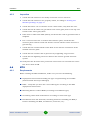
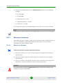
Section Orientation
Figure 20: Section Orientation
E.5
Equipment Sweep Test Results Interpretation
E.5.1
Cables
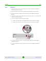
E.5.1.1
IF Cables- Results: 100 - 250 MHz Return Loss
A Return Loss sweep made at a frequency range of 100 - 250 MHz into a short or
an open shows the Insertion Loss of the cable x 2.
The IF signal travels from the analysis tool and then back from the end of the
cable to the analysis tool.
To receive the Insertion Loss of one direction, divide the loss reading by 2.
4Motion Installation Procedure
46
Reference Guide
ATP Sweep Testing Procedure
Figure 21: Return Loss
4Motion Installation Procedure
47
Reference Guide
ATP Sweep Testing Procedure
Figure 22: Return Loss 2
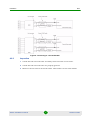
E.5.1.2
IF Cables- Results: 100 - 250 MHz Return Loss - Calibrated Load
Termination
To receive a Return Loss of -25 dB or better, connect a calibrated 50 Ohm load to
the end of the cable. If the shield is partially missing, the expected results for a
Return Loss sweep at these low frequencies is shown in the following graphs.
4Motion Installation Procedure
48
Reference Guide
ATP Sweep Testing Procedure
Figure 23: Return Loss: Calibrated Load Termination
4Motion Installation Procedure
49
Reference Guide
ATP Sweep Testing Procedure
Figure 24: Return Loss: Calibrated Load Termination 2
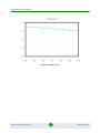
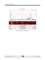
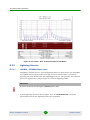
E.5.1.3
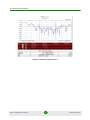
IF Cables- Results: 100 - 250 MHz Return Loss - Poorly Made
Connector
When the shield is partially open, it will show a higher Return Loss, even though
a calibrated 50 Ohm termination is at the far end connection.
4Motion Installation Procedure
50
Reference Guide
ATP Sweep Testing Procedure
Figure 25: Return Loss: Poorly Made Connector
4Motion Installation Procedure
51
Reference Guide
ATP Sweep Testing Procedure
Figure 26: Return Loss: Poorly Made Connector 2
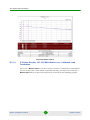
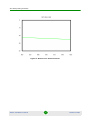
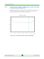
E.5.1.4
IF Cables- Results: 100 - 250 MHz Return Loss - Good Connector
When a cable is connected to a 50 Ohm calibrated load, the following results are
expected:
4Motion Installation Procedure
52
Reference Guide
ATP Sweep Testing Procedure
Figure 27: Return Loss: Good Connector
4Motion Installation Procedure
53
Reference Guide
ATP Sweep Testing Procedure
Figure 28: Return Loss: Good Connector 2
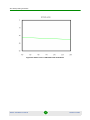
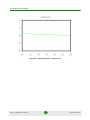
E.5.1.5
IF Cables- Results: 100 - 250 MHz Distance to Fault
To discover cable inconsistencies and severe cable damage, sweep the IF cable at
the frequency range of 100-250 MHz.
IMPORTANT
At this frequency, The sweep will show expected results even for poorly made connections.
4Motion Installation Procedure
54
Reference Guide
ATP Sweep Testing Procedure
Figure 29: DTF
4Motion Installation Procedure
55
Reference Guide
ATP Sweep Testing Procedure
Figure 30: DTF 2
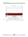
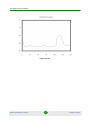
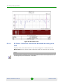
E.5.1.6
IF Cables- Results: 800 MHz - 1000 MHz Distance to Fault - Poor
Connector
A DTF sweep at this frequency discovers poor connectivity because the Return
Loss at the end is higher than the rest of the system average level.
4Motion Installation Procedure
56
Reference Guide
ATP Sweep Testing Procedure
Figure 31: DTF: Poor Connector
4Motion Installation Procedure
57
Reference Guide
ATP Sweep Testing Procedure
Figure 32: DTF: Poor Connector 2
4Motion Installation Procedure
58
Reference Guide
ATP Sweep Testing Procedure
E.5.1.7
IF Cables- Results: 800 MHz - 1000 MHz Distance to Fault - Poor Shield
Connection Closest to Analysis Tool
The following graphs are the results received for a DTF sweep carried out at the
frequency range of 800 MHz - 1000 MHz on an IF cable with a poor shield
connection located at the end closest to the analysis tool.
Figure 33: DTF - Poor Shield Connection Closest to the Site Master
4Motion Installation Procedure
59
Reference Guide
ATP Sweep Testing Procedure
Poor Shield Connection Closest to the Site Master 2
E.5.1.8
RF Cables - Return Loss Results: Bandwidth According to the ODU
The LMR400 Cables that operate at the bandwidth according to the ODU exhibit a
Return Loss of around 30 dB.
4Motion Installation Procedure
60
Reference Guide
ATP Sweep Testing Procedure
Figure 34: RF: Return Loss
4Motion Installation Procedure
61
Reference Guide
ATP Sweep Testing Procedure
Figure 35: RF: Return Loss 2
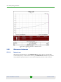
E.5.1.9
RF Cables - Distance to Fault Results: Bandwidth According to the
ODU
Properly made, short RF connectors (6-10 feet long) have a small rise in the
Return Loss at the coaxial cable termination from the radio into the antenna.
NOTE
At frequencies above 1000 MHz, the connectors and cable terminations have a higher Return Loss.
At these high frequencies disturbances are amplified.
4Motion Installation Procedure
62
Reference Guide
ATP Sweep Testing Procedure
Figure 36: RF Cables - DTF: Frequencies Above 1000 MHz
4Motion Installation Procedure
63
Reference Guide
ATP Sweep Testing Procedure
Figure 37: RF Cables - DTF: Frequencies Above 1000 MHz 2
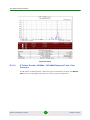
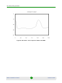
E.5.2
Lightning Arrestor
E.5.2.1
100 MHz - 250 MHz Return Loss
Polyphaser manufactures a special Lightning Protector that passes the Downlink
and Uplink Intermediate Frequencies (IF), but also passes Direct Current for
powering the ODU Radio Unit. The Lightning Protector also provides the required
protection against the voltage surges of a near hit lightning strike.
IMPORTANT
No device can protect the ODU against a direct lightning strike.
A good Lightning Protector has a higher than 25 dB Return Loss across the
operational band of the Lightning Protector equipment.
4Motion Installation Procedure
64
Reference Guide
ATP Sweep Testing Procedure
Figure 38: Lightning Protector - Return Loss
4Motion Installation Procedure
65
Reference Guide
ATP Sweep Testing Procedure
Figure 39: Lightning Arrestor - Return Loss 2
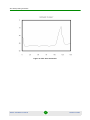
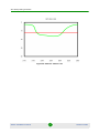
E.5.3
Microwave Antennas
E.5.3.1
Return Loss
All antennas should show a poor Return Loss at points that are outside the
resonant frequency of the antenna and a good Return Loss within the specified
and published specifications of the resonant frequency bands of the antenna.
4Motion Installation Procedure
66
Reference Guide
ATP Sweep Testing Procedure
Figure 40: Antenna - Return Loss
4Motion Installation Procedure
67
Reference Guide
ATP Sweep Testing Procedure
Figure 41: Antenna - Return Loss 2
4Motion Installation Procedure
68
Reference Guide