1
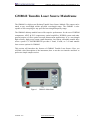
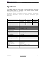
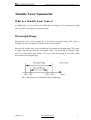
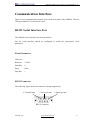
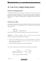
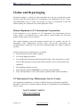
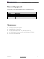
GM8042 Desktop Tunable Laser Source
User Manual
July, 2011
GM8042 Tunable Laser Source User Manual V1.30
Notices
This document contains UC INSTRUMENTS CORP. proprietary information that is
protected by copyright. All rights are reserved. This document can’t be reproduced in
(including electronic storage and retrieval or translation into a foreign language) without
prior agreement and written consent from UC Instruments Corp.
Subject Matter
The material in this document is subject to change without notice.
UC Instruments Corp. makes no warranty of any kind with regard to this printed
material, including, but not limited to, the implied warranties of merchantability and
fitness for a particular purpose.
UC Instruments Corp. shall not be liable for errors contained herein or for incidental or
consequential damages in connection with the furnishing, performance, or use of this
material.
Warranty
This UC Instruments Corp. product is warranted against defects in material and
workmanship for a period of 12 months from date of shipment. During the warranty
period, UC INSTRUMENTS CORP. will, at its option, either repair or replace products
that prove to be defective.
For warranty service or repair, this product must be returned to a service facility
designated by UC Instruments Corp. Buyer shall prepay shipping charges to UC
Instruments Corp. and UC Instruments Corp. shall pay shipping charges to return the
product to Buyer. However, Buyer shall pay all shipping charges, duties, and taxes for
products returned to UC Instruments Corp. from another country.
UC Instruments Corp. warrants that its software and firmware designated by UC
Instruments Corp. for use with an instrument will execute its programming instructions
when properly installed on that instrument. UC Instruments Corp. does not warrant that
the operation of the instrument, software, or firmware will be uninterrupted or error
free.
10440003 R001
www.ucinstruments.com
1
GM8042 Tunable Laser Source User Manual V1.30
Limitation of Warranty
The foregoing warranty shall not apply to defects resulting from improper or inadequate
maintenance by Buyer, Buyer-supplied software or interfacing, unauthorized
modification or misuse, operation outside of the environmental specifications for the
product, or improper site preparation or maintenance.
No other warranty is expressed or implied. UC Instruments Corp. specifically disclaims
the implied warranties of Merchantability and Fitness for a Particular Purpose.
Exclusive Remedies
The remedies provided herein are Buyer’s sole and exclusive remedies.
UC Instruments Corp. shall not be liable for any direct, indirect, special, incidental, or
consequential damages whether based on contract, tort, or any other legal theory.
Assistance
Product maintenance agreements and other customer assistance agreements are
available for UC Instruments Corp. products. For any assistance contact the UC
Instruments Corp. Maintenance Service Center.
Storage and Shipment
The instrument can be stored or shipped at temperatures between -30℃ and +80℃. The
instrument should be protected from temperature extremes that may cause condensation
within it.
10440003 R001
www.ucinstruments.com
2
GM8042 Tunable Laser Source User Manual V1.30
Safety Considerations
WARNING: The instrument is not designed for outdoor use. To prevent potential fire
or shock hazard, do not expose the instrument to rain or other excessive moisture.
The following general safety precautions must be observed during all phases of
operation, service, and repair of this instrument. Failure to comply with these
precautions or with specific warnings elsewhere in this manual violates safety standards
of design, manufacture, and intended use of the instrument. UC Instruments Corp.
assumes no liability for the customer’s failure to comply with these requirements.
Before operation, you should review the instrument and manual for safety markings and
instructions. You must follow these to ensure safe operation and to maintain the
instrument in safe condition.
WARNING: To avoid hazardous electrical shock, do not perform electrical tests
when there are signs of shipping damage to any portion of the outer enclosure (covers,
panels, and so on).
Line Power Connection
WARNING: To avoid the possibility of injury or death, you must observe the
following precautions before switching on the instrument.
l
Do not remove protective covers. Operating personnel must not remove instrument
covers. Component replacement and internal adjustments must be made only by
qualified service personnel.
l
Instruments that appear damaged or defective should be made inoperative and
secured against unintended operation until they can be repaired by qualified service
personnel.
l
Defective, damaged, or malfunctioning laser sources must be returned to UC
Instruments Corp. Maintenance Service Center.
l
Do not operate the instrument in the presence of flammable gases or fumes.
Operation of any electrical instrument in such an environment constitutes a definite
safety hazard.
10440003 R001
www.ucinstruments.com
3
GM8042 Tunable Laser Source User Manual V1.30
Contents
GM8042 Tunable Laser Source Mainframe ............................................................. 6
Specification ............................................................................................................... 7
Tunable Laser Summarize......................................................................................... 8
What is a Tunable Laser Source? ......................................................................... 8
Wavelength Range............................................................................................... 8
Description of the User Interface............................................................................... 9
User Interface Features........................................................................................ 9
Push Buttons and Knob ............................................................. 9
Laser Out Connector.................................................................. 9
LCD display .............................................................................. 9
How to Use the Module? .......................................................................................... 10
Initialization the Display Screen ........................................................................ 10
The Display Screen ........................................................................................... 10
How to Change the Value of a Parameter? ..........................................................11
How to Set the Wavelength?...............................................................................11
How to Set the Frequency? ................................................................................ 12
How to Set Output Power? ................................................................................ 12
How to Set the Wavelength Offset? ................................................................... 13
How to Set the Power Offset?............................................................................ 13
How to Set the Backlight? ................................................................................. 14
How to Set the Power Units? ............................................................................. 14
How to Enable the Laser Output? ...................................................................... 14
How to Disable the Laser Output? ..................................................................... 15
How to Set the Tunable Laser Units................................................................... 15
How to Perform a Sweep Testing? ..................................................................... 15
10440003 R001
www.ucinstruments.com
4
GM8042 Tunable Laser Source User Manual V1.30
What is a Wavelength Sweep Testing? .............................................15
How to Perform a Wavelength/Frequency Sweep Operation? ....15
How to Abort a Wavelength/Frequency Sweep Operation? .........15
How to Unlock the Remote Control Status?....................................................... 16
Software Control ...................................................................................................... 16
Software Installation.......................................................................................... 16
System Setup..................................................................................................... 18
Software Operation............................................................................................ 19
Communication Interface ........................................................................................ 21
RS232 Serial Interface Port ............................................................................... 21
Fixed Parameters ...................................................................................21
RS232 Connector ..................................................................................21
Cable ........................................................................................................22
USB Port ........................................................................................................... 22
USB Connector ......................................................................................22
USB Cable ..............................................................................................22
AC Line Power Supply Requirements..................................................................... 23
Line Power Requirements.................................................................................. 23
Line Power Cable .............................................................................................. 23
Claims and Repackaging ......................................................................................... 24
Return Shipments to UC Instruments Corporation ............................................. 24
UC Instruments Corp. Maintenance Service Center ........................................... 24
Standard Equipments .............................................................................................. 25
Maintenance ............................................................................................................. 25
UC INSTRUMENTS CORP. CONTACT INFORMATION ................................. 26
10440003 R001
www.ucinstruments.com
5
GM8042 Tunable Laser Source User Manual V1.30
GM8042 Tunable Laser Source Mainframe
The GM8042 is a high power Desktop Tunable Laser Source Module. The output can be
tuned to any wavelength within specified wavelength range. The GM8042 is also
capable of fast sweeping for any specified wavelength/frequency range.
The GM8042 desktop tunable lasers offer superior performance for the test of DWDM
components, AWG & PLC components, optical amplifiers, DWDM system and other
general purpose of fiber optical test and measurement applications. It is a wavelength
high accuracy, high power output, small dimension, fast startup, affordable tunable laser
source system. UC INSTRUMENTS provides C band, L band, or C+L band tunable
laser sources options for GM8042.
This section will introduce the features of GM8042 Tunable Laser Source. Here you
will find a brief description of the instrument, how to use the user interface and how to
perform a simple sample session.
Figure 1
10440003 R001
GM8042 Mainframe
www.ucinstruments.com
6
GM8042 Tunable Laser Source User Manual V1.30
Specification
The GM8042 Tunable Laser Source Module is produced to the ISO9001 international
quality system standard. UC Instruments Corp. continually increases customer
satisfaction through improved quality control.
Specifications describe the instruments warranted performance. Supplementary
performance characteristics describe the instruments non-warranted typical
performance.
Wavelength
Model #
GM8042C
GM8042L
GM8042CL
range
1525.00 to
1568.00 nm
1568.00 to
1610.00 nm
1525.00 to
1610.00 nm
>= 20 mW
>= 10 mW
>= 5.0 mW
25 dB
25 dB
Output Power
Power Adjust Range
Wavelength
resolution
25 dB
1.0 pm
Absolute wavelength accuracy
+/- 10 pm, tpy. < 5 pm
Relative wavelength accuracy
+/- 5 pm, Typ. +/- 2 pm
Wavelength repeatability
+/- 2 pm, typ. +/- 1 pm
Wavelength stability (typ., 24 hrs at
constant temperature
<= +/- 2 pm
Tuning speed
<= 0.02 s per step
Power stability
< +/- 0.1 dB, 24 hours.
Power repeatability
+/- 0.05 dB
Power linearity
+/- 0.3 dB
Power flatness versus wavelength
0.3 dB typ., 0.5 dB max.
Side-mode Suppression ritio
>= 40 dB
Relative intensity noise(RIN. Typ.)
< -135 dB
Power supply
AC 100 - 240 V ± 10%, 48 - 66 Hz, 100 VA max.
Environmental
Storage temperature
Operating temperature
Humidity
−40°C to +80°C
0°C to +45°C
<95% R.H. from 0°C to +45°C
Dimensions
200 mm W, 105 mm H, 250 mm D
Weight
9.0 lbs
10440003 R001
www.ucinstruments.com
7
GM8042 Tunable Laser Source User Manual V1.30
Tunable Laser Summarize
What is a Tunable Laser Source?
A tunable laser is a laser source for which the wavelength can be continuously tuned
into a specific wavelength in a specified range.
Wavelength Range
Each tunable laser source module has a specified wavelength range. This range is
available for same part number Tunable Laser Source modules.
Each specific tunable laser source module has a permitted wavelength range. This range
is bigger than the specification wavelength range. The permitted wavelength range
varies for each tunable laser module. You can set the wavelength to any value within
the permitted wavelength range.
Fig. 2 Specification and Permitted Wavelength Rang
10440003 R001
www.ucinstruments.com
8
GM8042 Tunable Laser Source User Manual V1.30
Description of the User Interface
LCD display
Power key
Knob
Laser out
Figure 3
Push buttons
RS232 Port
USB Port
AC Power coupler
User interface of the GM8042
User Interface Features
Push Buttons and Knob
All the control to GM8042 is via the push buttons and knob.
Laser Out Connector
FC/PC adapter connector for laser output.
LCD display
The LCD shows the wavelength, frequency and power values for laser source, and state
of laser output signal. If the module is performing a sweeping operation under remote
control, the LCD will show a prompt.
10440003 R001
www.ucinstruments.com
9
GM8042 Tunable Laser Source User Manual V1.30
How to Use the Module?
Initialization the Display Screen
When the GM8042 is powered up, the screen will show initial information, such as, the
serial number, hardware revision, firmware revision of the GM8042, and information
about detecting laser source.
SN: GG0428 44 001
HW Revision: 1.00
Hardware Revision: 1.00
Flash RAM
Figure 4
the initial information for GM8042
The Display Screen
Figure 4 shows the screen profile of the GM8042. This screen will show up
immediately after start-up. The screen shows the wavelength, frequency and power
values of the laser output signal.
State of laser output signal
Laser OFF
Output Wavelength
Output frequency
λ : 1550.0000nm
F : 191628.0GHz
13.01 dBm
Sweeping
RMT
Figure 5
10440003 R001
Output power
Remote Control
Perform a sweeping
optional
GM8042 Display Screen
www.ucinstruments.com
10
GM8042 Tunable Laser Source User Manual V1.30
How to Change the Value of a Parameter?
What follows is a description of the way of change the value of parameters.
1
2
Select the desired parameter.
The digit which was modified last of setting value is highlighted.
3
Pressing [◀] or [▶] pushbutton to move to the digit which is desired to edit.
4
Rotate the knob to modify the numeric of digit. Clockwise rotation increases the
numeric, and anticlockwise rotation decreases the Numeric.
Notice: The numeric is specified a range. When you rotates the knob, if the numeric
reaches it’s specified range, the LCD displays max or min value prompt.
How to Set the Wavelength?
For example, set the wavelength from 1550nm to 1545.00nm:
1
Press the [ λ/F ] button to select the wavelength parameter.
2
Press the [UNIT] button to move to the < λ > parameter.
3
Pressing [◀] or [▶] pushbutton to move to the third digit, 5, as shown in Figure 6.
Laser OFF
λ : 1550.0000nm
13.01 dBm
F : 191628.0GHz
Figure 6
Modify the <λ> parameter
4
Rotates the knob anticlockwise to decrease the current numerics to 4.
5
Pressing the [▶] pushbutton to move to the fourth digit, 0.
6
Rotates the knob clockwise to increase the current numerics to 5.
10440003 R001
www.ucinstruments.com
11
GM8042 Tunable Laser Source User Manual V1.30
How to Set the Frequency?
1
Press the [ λ/F ] button to select the wavelength parameter.
2
Press the [UNIT] button to move to the < F > parameter.
3
Pressing [◀] or [▶] pushbutton to move to the desired digit, as shown in Figure 7.
Laser OFF
λ : 1550.0000nm
13.01 dBm
F : 191628.0GHz
Figure 7
4
Modify the <F> parameter
Rotates the knob anticlockwise to decrease the current selected numeric and rotates
the knob clockwise to increase the current selected numeric.
How to Set Output Power?
1
Press the [ POWER] button to select the power parameter.
Laser OFF
λ : 1550.0000nm
13.01 dBm
F : 191628.0GHz
Figure 8 Modify the power parameter
2
Pressing [◀] or [▶] pushbutton to move to the desired digit, as shown in Figure 8.
3
Rotates the knob anticlockwise to decrease the current selected numeric and rotates
the knob clockwise to increase the current selected numeric.
10440003 R001
www.ucinstruments.com
12
GM8042 Tunable Laser Source User Manual V1.30
How to Set the Wavelength Offset?
1
2
Press the [ λ/F ] and [UNIT] buttons simultaneously to enter offset setting interface.
Press the [ λ/F ] to move to the < λ > parameter.
Offset :
Wave
λ : -0.000nm
B_Light : 100%
Figure 9
Power
-0.00 dB
Set the wavelength offset
3
Pressing [◀] or [▶] pushbutton to move to the desired digit, as shown in Figure 9.
4
Rotates the knob anticlockwise to decrease the current selected numeric and
rotates the knob clockwise to increase the current selected numeric.
5
The setting range of wavelength offset is from -50pm to +50pm.
6
Press the [UNIT] button to save it and exit.
How to Set the Power Offset?
1
2
Press the [ λ/F ] and [UNIT] buttons simultaneously to enter offset setting interface.
Press the [ POWER ] to move to the power parameter.
Offset :
Wave
λ : -0.000nm
B_Light : 100%
Figure 10
3
Power
-0.00 dB
Set the power offset
Pressing [◀] or [▶] pushbutton to move to the desired digit, as shown in Figure 10.
10440003 R001
www.ucinstruments.com
13
GM8042 Tunable Laser Source User Manual V1.30
4
Rotates the knob anticlockwise to decrease the current selected numeric and
rotates the knob clockwise to increase the current selected numeric.
5
The setting range of power offset is from -1dB to +1dB.
6
Press the [UNIT] button to save it and exit.
How to Set the Backlight?
1
2
Press the [ λ/F ] and [UNIT] buttons simultaneously to enter offset setting interface.
Press the [Active] to move to the backlight parameter, as shown in Figure 11.
Offset :
Wave
λ : -0.000nm
B_Light : 100%
Figure 11
3
Power
-0.00 dB
Set the Backlight
Rotates the knob anticlockwise to decrease the percent of backlight and rotates the
knob clockwise to increase the percent of backlight.
4
Press the [UNIT] button to save it and exit.
How to Set the Power Units?
1
Press the [ POWER] button to select the power parameter.
2
pressing the [ UNIT] button allows you to select either dBm or mW as the units in
which power is displayed.
How to Enable the Laser Output?
Press the [Active] button on the front panel of the GM8042 to enable the laser output. If
the Active LED is lit, the source is emitting radiation, and the LCD displays ‘Laser ON’
on the right of the top.
10440003 R001
www.ucinstruments.com
14
GM8042 Tunable Laser Source User Manual V1.30
How to Disable the Laser Output?
Press the [Active] button on the front panel of the GM8042 to disable the laser output. If
the Active LED goes out, the source stops emitting radiation, and the LCD displays
‘Laser OFF’ on the right of the top.
How to Set the Tunable Laser Units
1
2
Press the [ λ/F ] button to select the wavelength parameter.
pressing the [ UNIT] button allows you to select either λ or F, the units in which
wavelength is displayed.
How to Perform a Sweep Testing?
What is a Wavelength Sweep Testing?
A wavelength sweep testing is performed when the instrument changes the optical
wavelength of the optical output across a user-defined wavelength range. You can use a
wavelength sweep to measure the wavelength-dependent loss of an optical component.
How to Perform a Wavelength/Frequency Sweep Operation?
The GM8042 Tunable Laser Source is equipped with the PC software. You can perform
the wavelength or frequency sweep via this software.
See the “software control” section for detailed information on sweep operation.
How to Abort a Wavelength/Frequency Sweep Operation?
When the GM8042 is performing a wavelength or frequency sweep operation by the PC
software, pressing the [◀] button on the front panel aborts the sweep operation.
10440003 R001
www.ucinstruments.com
15
GM8042 Tunable Laser Source User Manual V1.30
How to Unlock the Remote Control Status?
When the GM8042 is under remote RS232 or USB control, all the manual buttons are
locked except [◀] and the LCD displays “RMT” on the right of the bottom.
Pressing the [◀] button can exit from the remote control.
Software Control
Software Installation
1
Install the .NET Framework software.
Install the .NET 3.5 by double clicking DotNET_Framework35.exe file. Please note
this step can be skipped for Windows 7 and windows vista.
l
Double click the DotNET_Framework35.exe file to unpack it.
l
After unpacking, install the .NET 3.5 according to the system prompts.
10440003 R001
www.ucinstruments.com
16
GM8042 Tunable Laser Source User Manual V1.30
l
Finish the installation for the Microsoft.NET 3.5。
2
Install the USB driver.
If you want to use USB port for communication with PC, before operating the
GM8042, the USB driver software must be installed first.
l
First find the file CP210x_VCP_Win_XP_S2K3_Vista_7.exe on the CD provided
with the instrument.
l
Double click the destination file, according to the prompt select the target path to
install the USB driver program.
10440003 R001
www.ucinstruments.com
17
GM8042 Tunable Laser Source User Manual V1.30
System Setup
1
Power up the GM8042.
2
Connect the PC to the GM8042 with the supplied USB cable, the PC will prompt for
installing the hardware automatically. After completing the installation, open the
windows device manager, and look for added comport under ‘comport(COM and
LPT)’.
3
The PC assigns a comport number automatically.
You can also use a RS232 cable supplied by UC Instruments Corp. to Connect the
PC to the GM8042.
Assume you use a USB port in this section.
4
Run the PC software, select the above comport (COM4 in this example), baud rate
is set to 115200, press ‘open’ button to establish the communication between the PC
and the GM8042.
10440003 R001
www.ucinstruments.com
18
GM8042 Tunable Laser Source User Manual V1.30
Software Operation
When the module communicates with pc, the interface is shown below. The user may
use this PC software to set the current output frequency/wavelength, perform sweep
operation and turning laser on/off.
l
Open/Close Communication Comport
Click open or close button, the communication comport will be enabled or disabled.
l
Set current frequency
Select frequency value on frequency drop-down box, then click [set value] button,
the frequency setting will be sent to module. If click the [Set to Max] or [Set to Min]
button, the current frequency will be set to maximum or minimum laser frequency
of the module.
10440003 R001
www.ucinstruments.com
19
GM8042 Tunable Laser Source User Manual V1.30
l
Set current wavelength
Select wavelength value on wavelength drop-down box, then click [set value]
button, the wavelength setting will be sent to module. If click [Set to Max] or [Set
to Min] button, the current wavelength will be set to maximum or minimum laser
wavelength of the module.
l Control laser output state: Set the laser state to “ON” to enable the laser output.
Set it to “OFF” to turn laser output off.
l Set sweeping Mode: in Mode drop-down box, specify the either frequency or
wavelength sweeping mode.
.
l Set frequency sweeping: in Freq Scan frame, specify the beginning and end values,
step value and wait interval between two steps in per drop-down box for frequency
sweeping. When ready, click [Set Value] to confirm, then press [Sweep] button to
start the sweeping operation.
l Set wavelength sweeping: in Wave Scan frame, specify the beginning and end
values, step value and wait interval between two steps in per drop-down box for
wavelength sweeping. When ready, click [Set Value] to confirm, then press [Sweep]
button to start the sweeping operation.
l Abort Sweeping: You can press [Abort] button to abort the sweeping in progress.
10440003 R001
www.ucinstruments.com
20
GM8042 Tunable Laser Source User Manual V1.30
Communication Interface
There are two communication interface ports on the rear panel of the GM8042. They are
USB port and RS232 serial interface port.
RS232 Serial Interface Port
The GM8042 serial interface has fixed parameters.
The PC serial interface should be configured to match the instrument’s fixed
parameters.
Fixed Parameters
These are:
Baud rate
115200
Data Bits
8
Parity
None
Stop Bits
1
RS232 Connector
The following figure shows the connector and pin assignments.
2- Transmit data
3- Received data
5-Signal ground
RS232 Connector
10440003 R001
www.ucinstruments.com
21
GM8042 Tunable Laser Source User Manual V1.30
RS232 Cable
The connectors pin assignments on the cable for RS232 Communication.
DB9 Connector
Pin
Notes
Received data
2
Transmit data
3
Signal ground
5
Pin
2
3
5
DB9 Connector
Notes
Transmit data
Received data
Signal ground
NOTE For serial communication use the null modem cable provided with your
instrument.
USB Port
The USB Port is for connection to PC with PC software.
USB Connector
This is a standard four-core type B USB connector.
USB Cable
The USB connection cable must not be extended beyond 5m. For distance over 5m, it is
possible to use a third party USB extender. Typically, they extend USB up to 50m.
10440003 R001
www.ucinstruments.com
22
GM8042 Tunable Laser Source User Manual V1.30
AC Line Power Supply Requirements
Line Power Requirements
The GM8042 Desktop Tunable Laser Source complies with over voltage category II
and can operate from the single-phase AC power source that supplies between 100V
and 240V at a frequency in the range 48 to 66 Hz. The maximum power consumption is
230mA under 115V voltage. The maximum power consumption is 120mA under 230V
voltage.
Line Power Cable
In accordance with international safety standards, the instrument has a three-wire power
cable. When connected to an appropriate AC power receptacle, this cable earths the
instrument cabinet.
GM8042 Power Key
The power key on the front panel of the GM8012 may turn on or turn off the power.
WARNING: To avoid the possibility of injury or death, you must observe the
following precautions before switching on the instrument.
l
Insert the power cable plug only into a socket outlet provided with a protective
earth contact. Do not negate this protective action by the using an extension cord
without a protective conductor.
l
Do not interrupt the protective earth connection intentionally.
The AC power requirements are summarized on the rear panel of the instrument.
AC INPUT:
100-240V~, 48-66Hz, 48~ 66Hz
230mA/115V, 120mA/230V,
AC Power Requirement Mark - GM8042
10440003 R001
www.ucinstruments.com
23
GM8042 Tunable Laser Source User Manual V1.30
Claims and Repackaging
If physical damage is evident or if the instrument does not meet specification when
received, notify the carrier and the UC Instruments Corp. Maintenance Service Center.
The Maintenance Service Center will arrange for repair or replacement of the unit
without waiting for settlement of the claim against the carrier.
Return Shipments to UC Instruments Corporation
If the instrument is to be shipped to a UC Instruments Corp. Maintenance Service
Center, attach a tag showing owner, return address, model number and full serial
number and the type of service required.
The original shipping carton and packing material may be reusable, but the UC
Instruments Corp. Maintenance Service Center will provide information and
recommendation on materials to be used if the original packing is no longer available or
reusable.
General instructions for repackaging are as follows:
l
Wrap instrument in heavy paper or plastic.
l
Use strong shipping container.
l
Use enough shock absorbing material around all sides of the instrument to provide
a firm cushion and prevent movement inside container. Protect control panel with
cardboard.
l
Seal shipping container securely.
l
Mark shipping container FRAGILE to encourage careful handling.
l
In any correspondence, refer to instrument by model number and serial number.
UC Instruments Corp. Maintenance Service Center
Any adjustment, maintenance, or repair of GM8012 must be performed by qualified
personnel. Contact your customer engineer through UC Instruments Corp. Maintenance
Service Center.
Tel:0773-5850657, 5803731
http://www.ucigl.com
10440003 R001
www.ucinstruments.com
24
GM8042 Tunable Laser Source User Manual V1.30
Standard Equipments
This appendix provides information about GM8042’s Standard Equipments.
Accessories
Model #
AC Power Cable
Description
Null modem cable
Standard four-core type B USB cable.
three-wire power cable
CD
Includes GM8042 User manual and PC software
RS232 Cable
USB Connection Cable
Maintenance
l
Avoid sharp vibration when operation.
l
Keep the head face of sensor clean.
l
Cover the channel adaptor on the front panel with the dust cap.
l
Don’t forcibly push or drag the connector out of the adaptor of GM8042.
l
Be careful for crash and fall-off.
10440003 R001
www.ucinstruments.com
25
GM8042 Tunable Laser Source User Manual V1.30
UC INSTRUMENTS CORP. CONTACT INFORMATION
UC INSTRUMENTS CORPORATION
Add: 37498 Glenmoor Dr., Fremont, CA 94536 USA
Tel: +1-510-366-7353
Fax: +1-510-353-1809
Email: [email protected]
Website: www.ucistruments.com
MAINTENANCE SERVICE CENTER,GUILIN,CHINA
Address:No.16 Yi Feng south road, GuiLin, China
Tel: +86 773 5850657
Fax: +86 773 5814532
Website: www.ucigl.com
10440003 R001
www.ucinstruments.com
26