1
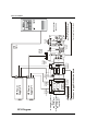
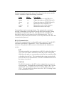
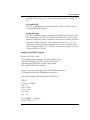
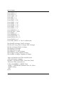
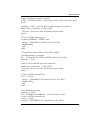
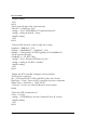
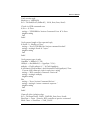
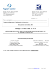
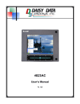
RCS User Manual
Series 2040 Test Systems
Relay Control System
Part Number #4200-0175
Version 1.7
Series 2040 Test System
1
RCS User Manual
Table of Contents
RELAY CONTROL SYSTEM ....................................................................................... 3
RCS Diagram ............................................................................................... 4
System Overview ......................................................................................... 5
System Operation ........................................................................................ 5
Power-Up Condition ........................................................................ 5
LED Status ........................................................................................ 5
2040 Interface ................................................................................. 6
Commands ....................................................................................... 6
RS-232 Communication ................................................................... 7
Echo ..................................................................................... 7
Baud rate ............................................................................. 7
Addresses ............................................................................. 8
Command Message .............................................................. 8
ACK and NACK .................................................................... 9
IEEE-488 Communication ............................................................... 10
RCS Configuration ............................................................. 10
Command Message ............................................................ 10
ACK and NACK .................................................................. 11
Return Message ................................................................. 11
Sample Visual BASIC Program ........................................................ 11
Maintenance .............................................................................................. 22
Switch Settings ............................................................................... 22
Mode Settings ............................................................................................ 22
RS-232 Settings .......................................................................................... 22
IEEE-488 Settings ........................................................................................ 23
Selftest Mode ................................................................................. 23
Controller Board Jumper Settings ................................................... 24
10-Amp RCS Relay Dis/Connect Board - PN# 0000-5232 ............. 25
30-Amp RCS Relay Dis/Connect Board - PN# 0000-5222 ............. 26
15-Amp RCS Relay Dis/Connect Board - PN# 0000-5322 ............. 26
Controller Board Connector Pinouts ............................................... 26
Relay Dis/Connect Connector Pinouts ............................................ 28
Specifications ................................................................................. 30
Appendix A ................................................................................................ 31
RCS Controller Board #0000-5244 ............................................... 31
10-Amp RCS Relay Dis/Connect Board #0000-5232 .................... 31
#0000-5222 30-Amp/0000-5322 15-Amp
RCS Relay Dis/Connect Boards ...................................................... 32
2
Series 2040 Test System
RCS User Manual
RELAY CONTROL SYSTEM
Version 1.7
Series 2040 Test System
3
4
P/S #1
Output
Cable
P/S #0
Fault/Inhibit
Cable
P/S #0
Output
Cable
Relay
Disconnect
Board #0
To Power Supply Distribution Board
Relay
RCS P/S #1 Output Disconnect
Board #1
RCS P/S #0 Output
10-A Relay Dis/Connect
(Shown)
PN# 0000-5232
(or 30-A Relay Dis/Connect
PN# 0000-5222
See page 32)
RCS Diagram
P/S #1
Fault/Inhibit
Cable
HP Power
Supply #1
HP Power
Supply #0
Controller
Board
GPIB
Cable
GPIB
Cable
RCS Controller
0000-5244
RCS Fault/Inhibit Cable to
Power Supply Controller Board
RCS Power Cable to
AC/DC Power Distributiuon Box
RS-232
Port
RCS User Manual
Series 2040 Test System
RCS User Manual
System Overview
The Relay Control System (RCS) is designed to control the output relays of the
GPIB power supplies on Digalog’s Series 2040D Tester. It consists of one
controller board plus one relay dis/connect board for each P/S output. A
diagram of the system is shown on page 6.
The RCS is a complete system which provides relay control for up to six sets
(Vout+, Vout-) of outputs from the GPIB power supplies. The 10-Amp and/or
30-Amp relays, which connect the outputs and the sense lines of the GPIB
power supplies to the Patchboard Receiver, are managed by an on-board
microcontroller which communicates with the host computer through either
its IEEE-488 or RS-232 interface to effect the execution of each GPIB-related
power functional call. The microcontroller also constantly monitors the system
fault loop and disengages all of the relays (and thus the GPIB power supplies’
outputs) if a fault signal has been generated either by a functional call or by
any of the UUT variable or GPIB power supplies. This prevents the GPIB
power supplies from possibly damaging or being damaged by the Unit-UnderTest (UUT). It also has a selftest mode to check its own functionality.
System Operation
Power-Up Condition
Upon power-up, the RCS controller executes a checksum test. The test
involves calculating and verifying the checksum of the entire firmware that the
on-board microcontroller executes. If the checksum test passes, the
microcontroller will be ready to accept and process commands from the host
computer.
LED Status
The two amber LEDs on the RCS controller board indicate the status of the
RCS controller. On a normal power-up, the firmware executes a PROM
checksum test. If the test passes, both of the LEDs remain off. But if the
calculated checksum is incorrect, then both LEDs will flash on and off
continuously. Under this condition, the RCS controller will not accept any
commands and should be powered off.
The amber LEDs will also blink on and off while the microcontroller accepts
and executes a valid command. When the board is in its selftest mode, the
Series 2040 Test System
5
RCS User Manual
amber LEDs will turn on when switch #8 on the switch bank is set to “Off.”
The green LED on each of the relay dis/connect boards (if more than one
GPIB P/S output exists) indicates that each relay’s upper coil pin is being
powered by +12V. The adjacent amber status LED will be off when the relays
are disengaged. This condition isolates the GPIB P/S outputs from the
Patchboard Receiver and thus the UUT. The relays will open either due to a
fault or via a software command. The amber LED will turn on whenever the
relays have been engaged.
These LEDs exist mainly for troubleshooting purposes and are not normally
visible during normal tester operations unless the right side panel has been
removed.
2040 Interface
This section refers to some 2040D functional calls and explains how they
interface with the Relay Control system. The TClear functional call
automatically opens all of the relays and thus disconnects all power supplies.
The PowerReset call opens one or all of the Relay Dis/Connect boards. The
PowerUUT or any related Power functional call closes the relays for the power
supply being programmed.
NOTE: To extend the contact life of the relays, use the PowerUUT
functional call to program the supply(s) to zero volts and zero amps before
using TClear or PowerReset to disengage the relays.
Commands
The 2040D tester contains all of the commands needed to control the RCS
controller within its functional call software. Each power-supply-related
functional call automatically detects the presence of a GPIB power supply and
issues the appropriate commands to engage or disengage the proper isolation
relays. The user does not need to add any of the RCS commands to the test
program. The material is presented only as background information in order to
provide a more complete explanation of how the RCS controller and relay dis/
connect boards function.
The RCS controller accepts commands from either the IEEE-488 or RS-232 bus
in ASCII form. There are six commands that can be issued to the RCS. The
first three commands operate the relays. The fourth and fifth commands ask
for the ID of the controller board and the version of the firmware, respectively.
6
Series 2040 Test System
RCS User Manual
The last command requests the status of the relays from the microcontroller.
The RCS controller accepts the following commands:
Name
all
openx
closex
id
version
status
Abbrev.
al
ox
cx
id
vn
ss
Description
Opens the relays for all (GPIB) P/S’s.
Opens the relays for (GPIB) P/S #x(0-5).
Closes the relays for (GPIB) P/S #x(0-5).
Returns the microcontroller’s ID.
Returns the version of the firmware.
Returns the status of the relays.
Commands are sent in a message format. The syntax for the command
message is dependent on the protocol through which the message is being
transmitted i.e., IEEE-488 or RS-232. The syntax for the commands is
described in detail for each protocol in the following sections. The “id”
command to request the microcontroller’s ID is only valid under the IEEE-488
communication protocol.
RS-232 Communication
The RS-232 communication is conducted through connector P1 on the RCS
controller board shown in Appendix A. This is a standard male DB-9
connector. The pinout for this connector is described in the Maintenance
section.
Echo
The microcontroller can communicate via RS-232 with echo either on
or off. The echo mode is selected by switch #2 on the switch bank.
With the echo mode on, any message received by the controller will be
echoed back on the line. This is required when using a terminal with
its local echo off to control the RCS. The RCS controller board is set at
the factory for echo off.
Baud rate
The RS-232 interface on the RCS can be configured to run at one of
four baud rates. The baud rates are selected by switches #4-5 on the
switch bank. The available baud rates are 9600, 4800, 2400, and
1200. To set the baud rate, please refer to the “RS-232 Settings” table
in the Maintenance section.
Series 2040 Test System
7
RCS User Manual
Addresses
The RCS controller can be set up with one of eight possible addresses
and will respond to commands designated only to its address. The
address is set using switches #6-8 and ranges from $80 to $87. Switch
settings for the different addresses are shown in the “RS-232 Settings”
table in the Maintenance section. This address must be specified in the
command message, which will be discussed in the next paragraph.
Command Message
The RS-232 command messages use OPTO 22 compatible syntax for
serial communication. The command message consists of three parts.
The first part contains the start-of-command character “>” followed by
two ASCII hex digits representing the address of the RCS controller. For
an address setting of $80, a command message would start with
“>80.”
The second part of the message contains the command. The valid
commands are “all,” “open,” “close,” “version,” and “status.” Also, the
commands can be abbreviated and can use either lower or upper case
letters.
The third and final part of the message contains a one-byte checksum
followed by a command terminator character. The checksum is
calculated by adding the ASCII value of each character in the
command message except for the start-of-command character “>.”
The sum is then divided by 256 and the integer remainder is the
checksum. The checksum is always sent as two hexadecimal
characters. An example message with the checksum calculation is
shown below. Valid command terminators are “.” and carriage return.
Two ASCII question mark characters, “??,” can be used as a wildcard
checksum for debugging purposes, but should not be used in the final
application.
The command to open the OUT+ and OUT- relays for the GPIB P/S
output #2 on an RCS controller set up to be addressed at $80 is
“>80o209.” The checksum is calculated as follows:
ASCII characters: 8 0 o 2
Decimal equivalent: 56 + 48 + 111 + 50 = 265
8
Series 2040 Test System
RCS User Manual
265/256 = 1 with a remainder of 9
The checksum characters are 09.
ACK and NACK
When the host computer sends a command to the RCS controller via
RS-232, the controller sends back a message stating whether or not the
command was executed successfully. If the command was executed
successfully, the RCS controller will return an “A” followed by a carriage
return. If the command was not executed successfully, it will return an
“N” followed by a two-digit error code and a carriage return e.g.,
“N05cr.” Table 1 contains a list of the errors that can be returned from
the RCS controller.
Table 1: RCS Error codes.
Value
01
02
03
04
05
Description
Unknown Error
Buffer Overrun
Bad Checksum
Bad Terminator
Bad Command Sequence
If the status command was sent to the controller, it will return an “A”
followed by the status, a two-digit checksum (based on the status value
only), and a carriage return. The status value consists of an 8-bit binary
number in hexadecimal format. The two leftmost bits are unused and
left as zero. The next bit reflects the status of the output relays for P/S
#5: 0 for open and 1 for closed. The remaining bits represent P/S’s
#4-0 in descending order. This is outlined in the table below:
Bit#
7
6
5
4
3
2
1
0
P/S #0 Engaged
P/S #1 Engaged
P/S #2 Engaged
P/S #3 Engaged
P/S #4 Engaged
P/S #5 Engaged
0
0
0
0
0
0
0
0
0
0
0
0
0
0
0
0
0
1
0
0
0
0
1
0
0
0
0
1
0
0
0
0
1
0
0
0
0
1
0
0
0
0
1
0
0
0
0
0
Series 2040 Test System
9
RCS User Manual
A typical message would be “A2163cr.” The “A” means that the status
command was executed correctly and the “21” means that only GPIB
P/S’s #0 & #5 have been programmed and connected to the
patchboard. The “63” is the checksum of “21” in hexadecimal format.
Finally, the carriage return, “cr,” is the message terminator.
IEEE-488 Communication
The IEEE-488 communication is conveyed through connector P2 on the
RCS controller board shown in Appendix A. This is a standard 24-pin IEEE488 connector.
RCS Configuration
The TMS9914A General Purpose Interface Bus (GPIB) Controller is the
IEEE-488 chip used on the RCS controller board. On power-up, the
IEEE-488 address is read from the switch bank and stored in the
TMS9914A. It is then put in listen-only mode, where the chip listens
for its address to be put on the IEEE-488 bus by the host computer.
When the controller is addressed, the TMS9914A performs the
required handshaking to accept the command message and stores the
message in the RCS buffer where the command is then read and
executed by the microcontroller. The microcontroller normally keeps
the GPIB chip in listen-only mode unless a status command has been
received. Then it will be put into talk mode and the status of the relays
will be transferred over the IEEE-488 bus. Afterwards, the GPIB
controller will be put back into listen-only mode.
The RCS controller supports the IEEE-488 protocol of sending the EOI
message with the last byte of a response.
Command Message
The IEEE-488 command message is slightly different than the RS-232
message. The IEEE-488 command message does not have a start of
command character, “>.” The IEEE-488 controller does have a specific
address, which is determined by five of the switches in the switch
bank. Refer to the “IEEE-488 Settings” table in the Maintenance
section. The host computer software issues commands to the desired
RCS device. The “all,” “open,” “close,” “id,” “version,” and “status”
commands remain the same, and a “.” is the command message
terminator. The IEEE-488 protocol does not use a checksum. For
10
Series 2040 Test System
RCS User Manual
example, the message “o1.” will open the output relays for GPIB P/S
#1.
ACK and NACK
The RCS controllerdoes not respond with an ACK or a NACK when
using the IEEE-488 protocol.
Return Message
The RCS controller returns a message when asked for the status of the
P/S’ output relays, the ID of the microcontroller, or the version of the
firmware. When the status command is sent to the controller, only the
status itself will be returned. The completion code (“A” or “N”), the
checksum, and the message terminator are not sent. A typical status
reply message would be “01.” The “01” means that all relays are open
except for those of P/S #0.
Sample Visual BASIC Program
Private Sub Form_Load()
‘This sample program engages P/S #0’s isolation relays
‘and then disengages P/S #0’s isolation relays after
‘first disengaging all of the isolation relays under
‘the control of the RCS controller.
‘
‘Note: To execute this program, the file GPIB.BAS located in
‘C:\Digalog\Include must be added to the project.
‘
‘The GPIB settings in the initiation file GPIB.INI are
‘
‘[DEV4]
‘Connect = GPIB0
‘Pad = 4
‘Sad = None
‘Tmo=10sec
‘Eos=0xd
‘Eot = Yes
‘
Const ERRBIT = &H8000
Const cGPIB_0 = 0
Series 2040 Test System
11
RCS User Manual
Const cPAD = 4
Const cSAD = 0
Const cTMO = 13
Const cEOT = 1
Const cEOS = 13
Const CMD1 = “id.”
Const CMD2 = “vn.”
Const CMD3 = “al.”
Const CMD4 = “c0.”
Const CMD5 = “o0.”
Const CMD6 = “ss.”
Const CMDLEN = 3
Const ID_RCS = “RDA”
Const IDLEN = 3
Const VERSNLEN = 2
Const STATUSLEN = 2
Const STATUS_ALL = 0
Const STATUS_0 = 1
Const TIME_PAUSE = 2 ‘Two (2) milliseconds
Dim BoardID As Integer, DevID As Integer
Dim ibcntl As Long, iberr As Integer, ibsta As Integer
Dim iErr As Integer, iStatus As Integer
Dim iReplyLen As Integer
Dim lStartTime As Long
Dim RdBack(1 To 100) As Integer
Dim strMsg As String, strReply As String
Dim LwrByte As Integer, UpprByte As Integer
‘Open and initialize the GPIB controller board
‘in the 2040 tester computer
BoardID = DLLibfind(“GPIB0”, ibsta, iberr, ibcntl)
‘Check for GPIB command error
If ((ibsta And ERRBIT) = ERRBIT) Then
strMsg = “GPIB IBFind Command: Error #” & iberr
MsgBox strMsg
End
End If
12
Series 2040 Test System
RCS User Manual
‘Open and initialize the RCS controller
DevID = DLLibdev(cGPIB_0, cPAD, cSAD, cTMO, cEOT, cEOS, ibsta, iberr,
ibcntl)
lStartTime = Timer ‘Pause for RCS controller to process command
While Timer < lStartTime + TIME_PAUSE
DoEvents ‘Process any other keyboard or mouse inputs
Wend
‘Check for GPIB command error
If ((ibsta And ERRBIT) = ERRBIT) Then
strMsg = “GPIB IBDev Command: Error #” & iberr
MsgBox strMsg
End
End If
‘Verify that the selected device is the RCS controller
‘Send IDentification command
iErr = DLLibwrt(DevID, CMD1, CMDLEN, ibsta, iberr, ibcntl)
lStartTime = Timer
‘Pause for RCS controller to process command
While Timer < lStartTime + TIME_PAUSE
DoEvents ‘Process any other keyboard or mouse inputs
Wend
‘Check for GPIB command error
If (iErr < 0) Then
strMsg = “GPIB IBWrt for ID Command: Error #” & iberr
MsgBox strMsg
End
End If
‘Fetch IDentification reply
iReplyLen = IDLEN
iErr = DLLibrd(DevID, RdBack(1), 100&, ibsta, iberr, ibcntl)
‘Check for GPIB command error
If (iErr < 0) Then
strMsg = “GPIB IBRd for ID Command: Error #” & iberr
Series 2040 Test System
13
RCS User Manual
MsgBox strMsg
End
End If
‘Verify proper length of the expected reply
If (ibcntl <> iReplyLen) Then
strMsg = “Error: GPIB IBRd for ID command fetched “
strMsg = strMsg & ibcntl & “ bytes.”
MsgBox strMsg
End
End If
‘Convert ANSI character codes in reply into a string
UpprByte = RdBack(1) / 256
LwrByte = Abs(RdBack(1) - (UpprByte * 256))
strReply = Chr$(LwrByte) & Chr$(UpprByte) & Chr$(RdBack(2))
‘Verify expected ID reply
If (strReply <> ID_RCS) Then
strMsg = “Error: Selected GPIB device is not “
strMsg = strMsg & “the RCS controller.”
MsgBox strMsg
End
End If
‘Display the RCS controller’s firmware version number
‘Send version command
iErr = DLLibwrt(DevID, CMD2, CMDLEN, ibsta, iberr, ibcntl)
lStartTime = Timer ‘Pause for RCS controller to process command
While Timer < lStartTime + TIME_PAUSE
DoEvents ‘Process any other keyboard or mouse inputs
Wend
‘Check for GPIB command error
If (iErr < 0) Then
strMsg = “GPIB IBWrt for Version Command: Error #” & iberr
MsgBox strMsg
End
End If
14
Series 2040 Test System
RCS User Manual
‘Fetch version reply
iReplyLen = VERSNLEN
iErr = DLLibrd(DevID, RdBack(1), 100&, ibsta, iberr, ibcntl)
‘Check for GPIB command error
If (iErr < 0) Then
strMsg = “GPIB IBRd for Version Command: Error #” & iberr
MsgBox strMsg
End
End If
‘Verify proper length of the expected reply
If (ibcntl <> iReplyLen) Then
strMsg = “Error: GPIB IBRd for Version command fetched “
strMsg = strMsg & ibcntl & “ bytes.”
MsgBox strMsg
End
End If
‘Verify proper type of reply
UpprByte = RdBack(1) / 256
LwrByte = Abs(RdBack(1) - (UpprByte * 256))
strReply = Chr$(LwrByte) & “.” & Chr$(UpprByte)
If (IsNumeric(Chr$(LwrByte)) And IsNumeric(Chr$(UpprByte))) Then
‘Convert ANSI character codes in reply into a string
strMsg = “RCS controller’s Firmware: Version #”
strMsg = strMsg & strReply
MsgBox strMsg
Else
strMsg = “Error: Version Command did not “
strMsg = strMsg & “return a numeric response.”
MsgBox strMsg
End
End If
‘Open all of the isolation relays
iErr = DLLibwrt(DevID, CMD3, CMDLEN, ibsta, iberr, ibcntl)
lStartTime = Timer ‘Pause for RCS controller to process command
While Timer < lStartTime + TIME_PAUSE
Series 2040 Test System
15
RCS User Manual
DoEvents ‘Process any other keyboard or mouse inputs
Wend
‘Check for GPIB command error
If (iErr < 0) Then
strMsg = “GPIB IBWrt for Opening All Relays: Error #”
strMsg = strMsg & iberr
MsgBox strMsg
End
End If
‘Verify that all of the isolation relays are open
‘Send relay status command
iErr = DLLibwrt(DevID, CMD6, CMDLEN, ibsta, iberr, ibcntl)
lStartTime = Timer ‘Pause for RCS controller to process command
While Timer < lStartTime + TIME_PAUSE
DoEvents ‘Process any other keyboard or mouse inputs
Wend
‘Check for GPIB command error
If (iErr < 0) Then
strMsg = “GPIB IBWrt for Status of All Open Relays: “
strMsg = strMsg & “Error #” & iberr
MsgBox strMsg
End
End If
‘Fetch relay status reply
iReplyLen = STATUSLEN
iErr = DLLibrd(DevID, RdBack(1), 100&, ibsta, iberr, ibcntl)
‘Check for GPIB command error
If (iErr < 0) Then
strMsg = “GPIB IBRd for Status of All Open Relays: “
strMsg = strMsg & “Error #” & iberr
MsgBox strMsg
End
End If
16
Series 2040 Test System
RCS User Manual
‘Verify proper length of the expected reply
If (ibcntl <> iReplyLen) Then
strMsg = “Error: GPIB IBRd for Status of All Open Relays “
strMsg = strMsg & “fetched “ & ibcntl & “ bytes.”
MsgBox strMsg
End
End If
‘Convert ANSI character codes in reply into a string
UpprByte = RdBack(1) / 256
LwrByte = Abs(RdBack(1) - (UpprByte * 256))
strReply = Chr$(LwrByte) & Chr$(UpprByte)
‘Verify proper type of reply
If (IsNumeric(strReply)) Then
iStatus = CInt(strReply)
Else
strMsg = “Error: Reply of Relay Status for “
strMsg = strMsg & “All Open Relays is non-numeric.”
MsgBox strMsg
End
End If
‘Verify expected relay status: all are disengaged
If (iStatus <> STATUS_ALL) Then
strMsg = “Error: Command to Open All Relays did not work.”
MsgBox strMsg
End
End If
‘Close the isolation relays for P/S #0
iErr = DLLibwrt(DevID, CMD4, CMDLEN, ibsta, iberr, ibcntl)
lStartTime = Timer ‘Pause for RCS controller to process command
While Timer < lStartTime + TIME_PAUSE
DoEvents ‘Process any other keyboard or mouse inputs
Wend
Series 2040 Test System
17
RCS User Manual
‘Check for GPIB command error
If (iErr < 0) Then
strMsg = “GPIB IBWrt for Closing P/S #0’s Relays: “
strMsg = strMsg & “Error #” & iberr
MsgBox strMsg
End
End If
‘Verify that P/S #0’s isolation relays are engaged
‘Send relay status command
iErr = DLLibwrt(DevID, CMD6, CMDLEN, ibsta, iberr, ibcntl)
lStartTime = Timer ‘Pause for RCS controller to process command
While Timer < lStartTime + TIME_PAUSE
DoEvents ‘Process any other keyboard or mouse inputs
Wend
‘Check for GPIB command error
If (iErr < 0) Then
strMsg = “GPIB IBWrt for Status of P/S #0’s Closed Relays: “
strMsg = strMsg & “Error #” & iberr
MsgBox strMsg
End
End If
‘Fetch relay status reply
iReplyLen = STATUSLEN
iErr = DLLibrd(DevID, RdBack(1), 100&, ibsta, iberr, ibcntl)
‘Check for GPIB command error
If (iErr < 0) Then
strMsg = “GPIB IBRd for Status of P/S #0’s Closed Relays: “
strMsg = strMsg & “Error #” & iberr
MsgBox strMsg
End
End If
‘Verify proper length of the expected reply
If (ibcntl <> iReplyLen) Then
strMsg = “Error: GPIB IBRd for Status of P/S #0 Closed Relays “
18
Series 2040 Test System
RCS User Manual
strMsg = strMsg & “fetched “ & ibcntl & “ bytes.”
MsgBox strMsg
End
End If
‘Convert ANSI character codes in reply into a string
UpprByte = RdBack(1) / 256
LwrByte = Abs(RdBack(1) - (UpprByte * 256))
strReply = Chr$(LwrByte) & Chr$(UpprByte)
‘Verify proper type of reply
If (IsNumeric(strReply)) Then
iStatus = CInt(strReply)
Else
strMsg = “Reply of Relay Status for P/S #0’s “
strMsg = strMsg & “Closed Relays is non-numeric.”
MsgBox strMsg
End
End If
‘Verify proper relay status
If (iStatus <> STATUS_0) Then
strMsg = “Error: Command to Close P/S #0’s Relays did not work.”
MsgBox strMsg
End
End If
‘Open the isolation relays for P/S #0
iErr = DLLibwrt(DevID, CMD5, CMDLEN, ibsta, iberr, ibcntl)
lStartTime = Timer ‘Pause for RCS controller to process command
While Timer < lStartTime + TIME_PAUSE
DoEvents ‘Process any other keyboard or mouse inputs
Wend
‘Check for GPIB command error
If (iErr < 0) Then
strMsg = “GPIB IBWrt for Opening P/S #0’s Relays: Error #”
Series 2040 Test System
19
RCS User Manual
strMsg = strMsg & iberr
MsgBox strMsg
End
End If
‘Verify that all of the isolation relays are open
‘Send relay status command
iErr = DLLibwrt(DevID, CMD6, CMDLEN, ibsta, iberr, ibcntl)
lStartTime = Timer ‘Pause for RCS controller to process command
While Timer < lStartTime + TIME_PAUSE
DoEvents ‘Process any other keyboard or mouse inputs
Wend
‘Check for GPIB command error
If (iErr < 0) Then
strMsg = “GPIB IBWrt for Status of P/S #0’s Open Relays: “
strMsg = strMsg & “Error #” & iberr
MsgBox strMsg
End
End If
‘Fetch relay status reply
iReplyLen = STATUSLEN
iErr = DLLibrd(DevID, RdBack(1), 100&, ibsta, iberr, ibcntl)
‘Check for GPIB command error
If (iErr < 0) Then
strMsg = “GPIB IBRd for Status of P/S #0’s Open Relays: “
strMsg = strMsg & “Error #” & iberr
MsgBox strMsg
End
End If
‘Verify proper length of the expected reply
If (ibcntl <> iReplyLen) Then
strMsg = “Error: GPIB IBRd for Status of P/S #0’s “
strMsg = strMsg & “Open Relays fetched “ & ibcntl & “ bytes.”
MsgBox strMsg
20
Series 2040 Test System
RCS User Manual
End
End If
‘Convert ANSI character codes in reply into a string
UpprByte = RdBack(1) / 256
LwrByte = Abs(RdBack(1) - (UpprByte * 256))
strReply = Chr$(LwrByte) & Chr$(UpprByte)
‘Verify proper type of reply
If (IsNumeric(strReply)) Then
iStatus = CInt(strReply)
Else
strMsg = “Error: Reply of Relay Status for P/S #0’s “
strMsg = strMsg & “Open Relays is non-numeric.”
MsgBox strMsg
End
End If
‘Verify proper relay status
If (iStatus <> STATUS_ALL) Then
strMsg = “Error: Command to Open P/S #0’s Relays did not work.”
MsgBox strMsg
End
End If
strMsg = “The Relay Control System operated correctly.”
MsgBox strMsg
End
End Sub
Series 2040 Test System
21
RCS User Manual
Maintenance
Switch Settings
The switch settings for the various operating modes are given below.
Mode Settings
Normal Operation
Selftest Mode
SW1 SW2 SW3
ON
OFF
Serial Echo Off
Serial Echo On
ON
OFF
IEEE-488 Comm.
RS-232 Serial Comm.
RS-232 Settings
9600 Baud
4800 Baud
2400 Baud
1200 Baud
RS-232 Address $80
RS-232 Address $81
RS-232 Address $82
RS-232 Address $83
RS-232 Address $84
RS-232 Address $85
RS-232 Address $86
RS-232 Address $87
22
ON
OFF
SW4
ON
OFF
ON
OFF
SW5 SW6 SW7 SW8
ON
ON
OFF
OFF
ON
OFF
ON
OFF
ON
OFF
ON
OFF
ON
ON
OFF
OFF
ON
ON
OFF
OFF
ON
ON
ON
ON
OFF
OFF
OFF
OFF
Series 2040 Test System
RCS User Manual
IEEE-488 Settings
IEEE-488 Address 0
IEEE-488 Address 1
IEEE-488 Address 2
IEEE-488 Address 3
IEEE-488 Address 4
...
IEEE-488 Address 31
SW4 SW5 SW6 SW7 SW8
ON
OFF
ON
OFF
ON
...
OFF
ON
ON
OFF
OFF
ON
...
OFF
ON
ON
ON
ON
OFF
...
OFF
ON
ON
ON
ON
ON
...
OFF
ON
ON
ON
ON
ON
...
OFF
Selftest Mode
The Selftest mode of the RCS controller board is invoked using the following
steps:
• Shutdown the computer operating system.
• Turn off the “Testhead,” “Accessories,” and “Computer” power
switches.
• Depress the red “Emergency Stop” button.
• Set switch #1 on the controller board’s switch bank to “Off” and all
of the other switches to “On.”
• Release the red “Emergency Stop” button by rotating it clockwise.
First, the microcontroller tests its firmware by calculating a checksum of its
PROM contents and comparing it to the expected value. If they do not
match, the test has failed. The microcontroller will then continuously pulse its
amber status LEDs and will not execute any more tests.
Otherwise, the microcontroller will then continuously monitor the settings of
switches #2-8 on the switch bank. For each switch between #2 and #7 that
is “On,” the microcontroller will turn off the amber LED on the corresponding
relay dis/connect board. For each switch that is “Off,” the corresponding
amber LED will be turned on. The table lists the association between the
switch number and the corresponding relay dis/connect board. During the
time that the LEDs are turned on and off, the relays are also exercised since
the same control line is used for both the LED and its corresponding relays.
However, the PTest routine must be used to functionally test the relays and the
attached cables.
Series 2040 Test System
23
RCS User Manual
Relay Select Lines on the RCS Controller Board
Switch#
Relay Dis/connect Board
2
3
4
5
6
7
0
1
2
3
4
5
The two amber status LEDs on the RCS controller board will turn on when
switch #8 on the switch bank is set to “Off.” They will turn off when switch
#8 is set to “On.”
Finally, the microcontroller will test its internal RAM memory when switch #1
on the switch bank is set back to “On.” If the test fails, the microcontroller will
continuously pulse its amber status LEDs. Otherwise, the amber status LEDs
will remain off.
To properly initialize the RCS controller board for normal operations after it
has entered its Selftest mode, set switch #1 to “On” and the other switches to
the proper positions for the desired communication mode and settings,
depress and then release the red “Emergency Stop” switch, and finally turn on
the Computer,” “Accessories,” “and “Testhead” power switches.
Controller Board Jumper Settings
RCS Controller Board
Reference
JP1
JP2
JP3
JP4
24
Status
Out
Out
Out
Out
Description
Factory Use Only
Factory Use Only
Factory Use Only
Factory Use Only
Series 2040 Test System
RCS User Manual
10-Amp RCS Relay Dis/Connect Board - PN# 0000-5232
Jumpers 1-6 define the board’s ID number. Only one of the six jumpers
should be installed at one time (if any). If the GPIB power supply has its own
relay control output signal, then none of the jumpers JP1-6 should be
installed.
Jumpers 7-8 terminate the RCS system’s fault/inhibit signal loop that is
connected in series to each fault/inhibit-capable GPIB power supply and each
relay dis/connect board.
Jumpers 9-10 bypass the fault/inhibit signals around its non-fault/inhibitcapable GPIB power supply to keep the fault/inhibit signal loop intact.
Reference
JP1
JP2
JP3
JP4
JP5
JP6
JP1-6
JP7-8
Status
In*
In*
In*
In*
In*
In*
Out
In
Out
JP9-10
D1
In
Out
D2
Description
Relay Board #5
Relay Board #4
Relay Board #3
Relay Board #2
Relay Board #1
Relay Board #0
GPIB P/S has sole control of its isolation relays.
Relay board is the farthest one away from the
controller board.
Relay board is not the farthest one away from the
controller board.
GPIB P/S has no fault/inhibit signal connections.
GPIB P/S has fault/inhibit signal connections.
An amber LED that signifies when the relays are
engaged and connect the outputs of the power
supply to the Patchboard Receiver.
A green LED that signifies when power is applied
to the board.
* - Mutually exclusive i.e., only one of the six jumpers should be installed.
Series 2040 Test System
25
RCS User Manual
30-Amp RCS Relay Dis/Connect Board - PN# 0000-5222
The 0000-5222 30-Amp Relay Dis/Connect board is a direct plug-in
replacement of the 0000-5232 10-Amp Relay Dis/Connect board including
connector pin assignments and jumper settings with the following exception:
TB1 is a 4-pin connector on the 10-Amp Relay Dis/Connect board, but
a 6-pin connector on the 30-Amp Relay Dis/Connect board to be
cabled to the GPIB or HPIB supply.
15-Amp RCS Relay Dis/Connect Board - PN# 0000-5322
The 0000-5322 15-Amp Relay Dis/Connect board is a higher voltage
adaptation of the 30-Amp RCS Board. Its connector pin assignments and
jumper settings are identical to the 30-Amp board except for TB1 and TB2.
Controller Board Connector Pinouts
The RCS controller board has connectors for RS-232 (P1) and IEEE-488 (P2).
The 9-pin (male DB-9) RS-232 connector is configured as a DTE with the
following pinout for P1:
Pin
1
2
3
4
5
6
7
8
9
Function
Pulled Up to +10V
Rx - Receive
Tx - Transmit
Pulled Up to +10V
GND - System Ground
Pulled Up to +10V
RTS - Request to Send
CTS - Clear to Send
Not Connected
The 24-pin IEEE-488 connector offers a full implementation of the IEEE
standard with the following pinout for P2:
Pin
1
2
3
4
5
26
Function
DI0 - Data Bit #0
DI1 - Data Bit #1
DI2 - Data Bit #2
DI3 - Data Bit #3
EOI
Series 2040 Test System
RCS User Manual
6
7
8
9
10
11
12
13
14
15
16
17
18
19
20
21
22
23
24
DAV
NRFD
NDAC
IFC
SRQ
ATN
GND - System Ground
DI4 - Data Bit #4
DI5 - Data Bit #5
DI6 - Data Bit #6
DI7 - Data Bit #7
REN
GND - System Ground
GND - System Ground
GND - System Ground
GND - System Ground
GND - System Ground
GND - System Ground
GND - System Ground
Connector P3 interfaces with the RCS Fault/Inhibit Cable which is connected
to the Power Supply Controller board with the following pinout:
Pin
1
2
3
4
Function
+ HP Fault
- HP Fault
+ HP Inhibit
- HP Inhibit
Connector P4 interfaces to the RCS Power Cable from the AC/DC Power
Distribution Box with the following pinout:
Pin
1
2
3
4
5
Series 2040 Test System
Function
GND
GND
GND
+12V
+12V
27
RCS User Manual
Connector P5 is the RCS “bus” connector providing the relay dis/connect
boards with select lines, 12V power, and Fault & Inhibit signals as follows:
Pin
1
2
3
4
5
6
7
8
9
10
11
12
Function
+ T/H HP Fault
- T/H HP Fault
+ T/H HP Inhibit
- T/H HP Inhibit
Relay Driver Select #0
Relay Driver Select #1
Relay Driver Select #2
Relay Driver Select #3
Relay Driver Select #4
Relay Driver Select #5
12V Power
12V Return
Relay Dis/Connect Connector Pinouts
The pinouts of connectors P1 and P3 on the relay dis/connect boards are
identical to that of connector P5 on the RCS controller board. Connector P2 is
used to interface with the HPIB or GPIB power supply as follows:
Pin
1
2
3
4
5
6
7
8
28
Function
+ P/S Fault
- P/S Fault
- P/S Inhibit
+ P/S Inhibit
N/C - No Connection
+12V
P/S Relay Driver Return
P/S Relay Driver Select
Series 2040 Test System
RCS User Manual
Connector TB1 interfaces to the outputs from the GPIB/HPIB power supplies
as follows on the:
0000-5232 10-A Relay Dis/Connect Board:
TB1
Pin
1
2
3
4
Function
+ Out
+ Sense
- Sense
- Out
Cable Wire
White (14AWG)
White/Red (20AWG)
White/Black (20AWG)
Black (14AWG)
0000-5222 30-A Relay Dis/Connect Board:
TB1
Pin
1
2
3
4
5
6
Function
+ Out1
+ Out2
+Sense
- Sense
- Out1
- Out2
Cable Wire
Red (14AWG) (either)
Red (14AWG) (either)
Black/White (20AWG)
Black (20AWG)
Black (14AWG) (either)
Black (14AWG) (either)
0000-5322 15-A Relay Dis/Connect Board:
TB1
Pin
1
2
3
4
5
6
Series 2040 Test System
Function
+ Out1
+ Sense
N/C
N/C
- Sense
- Out1
Cable Wire
Red (14AWG)
Black/White (20AWG)
None
None
Black (20AWG)
Black (14AWG)
29
RCS User Manual
Connector TB2 routes the GPIB/HPIB outputs to the Patchboard Receiver as
follows:
0000-5222 & 0000-5232
TB2
Pin
1
2
3
4
5
6
Function
+ Out1
+ Out2
+Sense
- Sense
- Out1
- Out2
Cable Wire
White (14AWG) (either)
White (14AWG) (either)
White/Red (20AWG)
White/Black (20AWG)
Black (14AWG) (either)
Black (14AWG) (either)
Pin
1
2
3
4
5
6
Function
+ Out1
+ Out2
N/C
N/C
- Out1
- Out2
Cable Wire
White (14AWG)
White/Red (20AWG)
None
None
WhiteBlack (20AWG)
Black (14AWG)
0000-5322
TB2
Specifications
Communication protocols:
IEEE-488 ........................ SH1,AH1,T4,TE0,L2,LE0,SR0,RL0,PP0,DC1,DT0,C0
RS-232 .............. 9600 Baud, 8 bits, no parity, 1 stop bit, x-on/x-off handshake
30
Series 2040 Test System
RCS User Manual
Appendix A
Assembly View of RCS Controller Board #0000-5244
P2
P1
P5
SW1
P3
P4
Assembly View of 10-Amp RCS Relay Dis/Connect Board #0000-5232
P2
D1
TB1
D2
P3
TB2
Series 2040 Test System
JP1
2
3
4
5
6
7
8
9
JP10
P1
31
RCS User Manual
Assembly View of #0000-5222 30-Amp/0000-5322 15-Amp
RCS Relay Dis/Connect Boards
Power Supply
Output Cable
To Patchboard
Receiver
To next Relay
Dis/Connect board
if available
From Previous
Relay Dis/Connect
board or Controller
Board
Power Supply
Fault/Inhibit cable
32
Series 2040 Test System