1
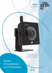
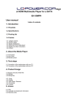
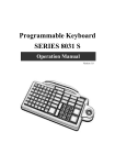
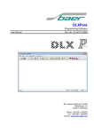
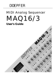
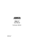
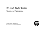
Magnetic Stripe Reader
SERIES 1288
Operation Manual
Version 1.0
User’s Manual
MSR 1288 series
Table of Contents:
Chapter 1 Introduction .....................................................................................2
Chapter 2 Appearance .....................................................................................3
Chapter 3 Installation ......................................................................................4
Chapter 4 Custom Programming Tool..........................................................14
Appendix I – Specification .............................................................................20
Troubleshooting .............................................................................................23
1
User’s Manual
MSR 1288 series
CHAPTER 1
Introduction
This product is an advanced bi-directional, programmable magnetic
stripe reader.Supports ISO standard(7810,7811,7812,7813) format
card.It is designed for use with credit authorization terminals,
point-of-sale terminals,portable terminals, personal computers and
banking terminals.
Model MSR K is designed to be used with IBM AT compatible
computer, entering data. As if it were being generated though the
Keyboard, no software modification, nor Programming of input/output
devices, nor Addition power supply is needed.Model MSR R operates
as an on-line card reader which communicates with any computer via
an RS232 interface.
The MSR R requires +5v DC from either an external power supply
or internal power of your computer or terminal. Model MSR U with
USB 1.1 Interface ,Communicates with any computer via USB ports .
With the special Windows driver,it can emulate a Visual COM in the
Windows and Application can access via this com port to communicate
with MSR U .
2
User’s Manual
MSR 1288 series
CHAPTER 2
Appearance
3
User’s Manual
MSR 1288 series
CHAPTER 3
Installation
MSR KB series:
The MD-6M side of KB cable, shall be connected to PC PS/2 Keyboard port.
The MD-6F side of KB cable can be connected to normal PC keyboard, PC keyboard can work with
the product together.
4
MSR 1288 series
User’s Manual
MSR RS232 series:
The DB-9F side of RS232 cable connects to PC COM port (COM 1 or COM 2 or other COMs)
, and power connects to USB .
5
User’s Manual
MSR 1288 series
MSR USB installation
Step 1: Connect to the computer
Plug the USB-connector into the USB port of your computer.
Refer to Figure 2-1. 6
MSR 1288 series
User’s Manual
MSR USB will have “Beep” sound to indicate that it is ready for operation.
Step 2: Driver installation
v2.0.0.19 for Win98SE/ME
v2.0.2.1 for Win2K/XP/2003/Vista(32bit)
PL-2303 (H, HX, X chip version) Mac OS 8 & 9 driver v1.3.6 build 1, Prolific Edition
PL-2303 (Chip H/HX/X) Linux driver for RedHat 7.3/8.0/9.0 Only
MSR USB simulates RS232 and Keyboard interface by USB with COM port selected.
Following sections are MSR USB driver, utilities installation.
MSR USB Driver:
a. Download MSR USB Driver from CD, and extract them to your hard disk.
b. When you plug-in the USB device, WINDOWS operating system will detect the new Hardware
automatically.
c. Follow indicated steps to install the driver and finish the installation.
7
User’s Manual
MSR 1288 series
Install for WindowsXP
1. Insert CD-Rom and select "MSR USB Driver" folder.
2. Then select "USB for Win SERIES" folder.
8
User’s Manual
MSR 1288 series
3. Select "PL-2303 Driver Install.exe".
4.When the setup screen appears then to select "Next" step.
9
User’s Manual
MSR 1288 series
5. After the installation completes, please select " Finish" and restart the computer.
1288 USB Driver for Windows
Specification.:
1. Support Microsoft Windows 95,98,ME,NT,2000,XP
2. Support Visual COM port.
3. Plug and Play.
How to Install:
1.When you plug-in 1288 USB, Windows operating system will detect
new hardware.
a. Follow indicated steps to install the drivers (Please select the driver in the
disk) and finish the installation.
How to Test Visual COM:
1. After you installed 1288USB driver, then hardware will assign an USB
simulated COM for 1288USB. So, you have to check the USB
assigned COM port from “Device Manager” of windows operating
system before you starting to get data from 1288USB .
2. Use COM test software to open simulated com port .
Setting COM port as 9600-N-8-1.
3. Striping the magnetic card, tracks data will be shown on the screen.
10
User’s Manual
MSR 1288 series
Install for Linux
1288 USB Linux Driver:
Linux Driver Support for RedHat 7.3 / 8.0 / 9.0 Only
1. At present, the determination uses the core edition(below blue typeface
is under the linux instuction).
[root@JuiLinux root]# uname -a
Linux JuiLinux.jarltech.com.tw 2.4.18-14 #1 Wed Sep 4 12:13:11 EDT 2002 i686 athlon
i386 GNU/Linux
2. After the product installation, it determines the driver has written down correctly
(joins PC USB port to able to hear "Beep").
[root@JuiLinux root]# lsmod | grep pl
pl2303
14424
0
usbserial
22108
0 [pl2303]
usbcore
77056
1 [pl2303 usbserial hid usb-ohci]
11
User’s Manual
MSR 1288 series
3. Obtain the data from USB0.
[root@JuiLinux root]# cat < /dev/ttyUSB0
4. After the card has brushed the material which delivers.
12
User’s Manual
MSR 1288 series
1288 USB / Device and Driver block chart v1.0
1288 MSR
Micro controller
Software:
Open Visual COM port to read data
From 1288
With Decoder
(UART Interface)
Magnetic Head
And data buffer board
Or direct control 1288 by sending
Command codes.
Prolific PL2303
USB to UART
Prolific USB Driver for OS:
Install to Creates a Visual COM
for application. Read/write.
PC USB port
1288 Handshake with visual COM
1. 1288 uses RTS / CTS handshake check with USB-RS232 chip.
2. When PC software needs to send data to 1288, check CTS of PC side in advance.,
If no action, it means 1288U is busy, PC software stop sending data, wait for CTS ready then start sending.
3. When 1288 needs to send data to PC, check CTS of 1288side in advance.
If not active, means PC is busy, 1288 stop sending data, wait for CTS ready then start sending.
RTS
1288
CTS
CTS
RTS
13
USB-RS232
Chip
User’s Manual
MSR 1288 series
CHAPTER 4
Custom Programming Tool
The MSR series doesn’t need any drivers for PC. For K series (MSR K), it can emulate normal
keyboard interface, and send the data as normal PC keyboard.
You can get the card data by using notepad (Windows system) or in DOS prompt or any words editor.
For R series (MSR R), it communicates via RS232 port (COM) to PC.
You can connect MSR R to a RS232 COM port on PC which is free for using (for example: COM2) and
getting the card data by some kinds of RS232 communication software. In programming language software,
just open the COM ports for reading data. For example in Visual Basic, use MSCOMM32.OCX for designing
the RS232 communication program and getting the card data.
All settings of MSR can be programmed by the programming tool which include in the CD,
The programming tool supports for Windows OS system like: Windows 95/98/Me/NT/2000/XP …
Please install the "setup.exe " before you restart your Windows operating system. After finished the installation
, please run the "programming tool.exe" for starting programming.
1. Auto detecting the MSR K/MSR R
The programming tool will start to detect automatically the MSR/MSR R which was connected to PC. You
can press the button [CANCEL] to abort the auto detection.
2. Main interface sets
If Auto detection was ok, then main screen shows the operating mode of MSR that you are using. The
image PIC-01 will be shown when MSR K (keyboard mode) detected.
Or, The main screen will be shown as PIC-02 when MSR R (RS232 mode) detected.
(The COM port is 2 for example)
14
User’s Manual
MSR 1288 series
PIC-01
PIC-02
15
User’s Manual
MSR 1288 series
Keyboard Mode:
KB mode Scan Code delay
The range is between is 0~255, default is 1.
Set the large value will slow down the speed of KB data sends out, yet it will be more compatible if you
are facing the problem with slow PC.
KB mode Character Code delay
The range is between is 0~255, default is 10.
Set the large value will slow down the speed of KB data sends out, yet it will be more compatible if you
are facing the problem with slow PC.
RS232 mode:
Com port value is for MSR R exists.
Baud rate is for setting MSR R RS232 communicates speed.
Buzzer Sound:
For enable / disable sounds of MSR, please click the check box for setting.
3. MSR Setting
16
User’s Manual
MSR 1288 series
Error Beep Sound
For enable / disable sound when MR reads card and error happened.
Prefix / Suffix
Enable or disable prefix / suffix for card data
When on the check box, you can edit the prefix / suffix, key in up to 7 characters.
You can key in data in text field directly, or use the mouse click the number and then enter the ASCII code.
Note:
The format of output data is:
[Prefix] [Track1 data] [Track2 data] [Track3 data] [Suffix]
[Track x data] = [Track x prefix] [Start sentinel] [card data] [End sentinel] [LRC sentinel] [Track x suffix]
[card data] = [ISO data field 1] [ISO data field 2] [ISO field 3] [CR] [LF]
Refer to MSR track 1/2/3 settings, and ISO format settings for the details.
High compatible TK1,TK2,TK3
For enable / disable high compatible mode for reading data from Track1/2/3
, to enable the option, the decoder will turn off some digit check for reading card data,
It will be more efficient to read bad cards which used for long time and damaged a little bit.
KB data output mode
To set Scan Code mode, and then card data will be sent to PC by scan code, it emulates the normal
keyboard code. To set ALT mode, card data will be sent by ASCII code mode.
4. MSR Track1 / Track 2 / Track 3 individual Setting
Double click the “MSR main settings”, will show up another track1/track2/track3 settings,
Please choose one of them for setting.
17
User’s Manual
MSR 1288 series
Error Beep Sound
For enable / disable sound when MSR reads card and error happened.
Prefix / Suffix
Enable or disable prefix / suffix for card data
Start Sentinel
Enable / Disable track start sentinel
(Track 1 start sentinel is “% “, Track 2 / 3 start sentinel is “; “ )
End sentinel
Enable / Disable track end sentinel
(The end sentinel is “? “ for all tracks)
LRC sentinel
Enable / Disable track LRC sentinel
(LRC = first byte data XOR second byte data XOR third byte data
….. last bye data)
TKx swipe from left to right and swipe from right to left
You can make choice to decide the user to swipe card and read data only from left to right or from right
to left or both ways.
5. MSR ISO Standard Field Setting
18
User’s Manual
MSR 1288 series
The track data can be split by the “Field splitting Enable/Disable”.
If the card you used was recoded by ISO standard field format, you can decide what fields you
want to display. The default is set to display all fields.
Every field can be split by LF (line feed) or CR (carriage return), Please make choice on [Send LF (Line
feed) after field data] or [Send CR (Carriage return) after field data].
6. Load Main Setting From MSR
Choose for up loading settings from the device to PC, this function only can be active by RS232 cable.
7. Detect Firmware Version
Choose for detecting firmware version of current the device, this function only can be active by RS232
cable.
8. Reset MSR to Factory Default
Choose for resetting the device to factory default settings, this function can be active either with KB or
RS232 cable.
9. Programming all settings
Choose for writing all settings you defined to MSR, please select via keyboard or via RS232 which
depends on what cable you are using.
19
User’s Manual
MSR 1288 series
Appendix I : Specifications
Model
1288
Decoding Capability
Triple-tracks: Tracks 1 & 2 & 3
7.5 to 125 cm/sec
Card Reading Speed
Bi-directional
Magnetic Head Life
300,000 passes
Card Format Supports
ISO standard 7810,7811,7812,7813
Status Indicator
Audible beep for each
Successful reading
Track selection
Prefix (7 characters max.)
Suffix (7 characters max.)
Field selection
Programming Capabilities
Start and end sentinel
LRC selection
Inter-character delay
Inter-scan code delay
RS232 parameters (baud rate,)
RS232C interface : IBM AT, Compatibles.
System Compatibilities
USB interface : USB port on IBM AT or compatibles
Keyboard Wedge Interface : IBM AT, PS/2
Model MSR K: from KB port.
Power Requirement
Model MSR R: from USB power(+5V DC)
Model MSR U: from USB port (+5V DC)
During operation: max 300 mA
Power Consumption
While idle: 60 mA
Physical Dimension
Dimension
(L)x(W)x(H)mm
Weight
Physical: 115mm x 46mm x 34mm
Package: 238mm x 146nn x 47mm
N.W: 100g
G.W: 110g
Color
Black, White
Environment
Operating Temperature
0℃~ 45℃ (32℉ ~ 113℉)
Storage Temperature
Operating Humidity
0% ~ 80% RH non condensing Storage Humidity
Certification
EMC & Safety
FCC, CE, RoHS, Class A
20
-20℃~ 60℃ (-4℉~ 140℉)
10% ~ 90% RH non condensing
User’s Manual
MSR 1288 series
This equipment has been tested and found to comply with the limits for Class A digital device. Pursuant
to part 15 of the FCC Rules. These limits are designed to provide reasonable protection against harmful
interference in a residential installation. This equipment generates, uses, and if not installed and used
in accordance with the instructions may cause harmful interference will not occur in a particular
installation. If this equipment does cause harmful interference to Radio or television reception, which
can be determined by turning the equipment off and on. The user is encouraged to try correct
interference by one or more of the following measures:
- Reorient or relocate the receiving antenna.
- Increase the separation between the equipment and receiver.
- Connect the equipment into an outlet on a circuit different from that to which the receiver is connected.
- Consult the dealer or an experienced radio/TV technician for help. This booklet is available from the
U.S. government Printing Office, Washington, DC 20402, Stock NO.004-000-00345-4.
Caution: Any changes of modifications not expressly
approved by the grantee of this device could void the
user authority to operate the equipment.
Operation is subject to the following two conditions:
(1) This device may not cause harmful interference.
(2) This device must accept any interference received including Interference that may cause undesired
operation.
21
User’s Manual
MSR 1288 series
Troubleshooting
Q1. When 1288 USB plug-in the USB port, the operating system will require to install
the driver?
Ans: It needs to install the specialized driver of 1288 USB. After installation, it will
produce a virtual COM port in the administrator.
Q2: 1288 USB swipes with “Beep” sound, but the data can’t show up on the screen.
Ans: Step 1. Confirm the 1288 driver installation properly.
Step 2. Confirm the testing program of RS232 or COM operating properly and the
Step 3. Confirm the Baud Rate of opening COM port is 9600.
Step 4. Confirm there is no application program using the COM port.
Step 5. If the “Beep” sound is long-short-short, it means the card reader can’t
read the data from the card. Please check the card status in advance is
available or change new card for testing.
Q3.1288 USB plug-in to USB port, there is no reaction.
Ans: A. Use other USB devices for testing the USB port is available or not.
B. If the USB port is ok, use new 1288 USB for testing the unit is available or not.
If not available, it means the 1288 USB is damaged.
Q4. The 1288 USB transmission speed?
Ans: Please note the USB communication Interface is 1.1 Version. The transmission
Baud Date of the virtual RS232 COM port is 9600bps-N-8-1.
Q5. Why 1288RS232 needs to connect the 5V Power supply?
Ans: Because the PC Standard COM port doesn’t provide the output of power.
Q6. What is the function of the switches in 1288?
Ans: Please refer to 1288 manual explanation.
Q7. After connecting the cable of 1288 K keyboard to PC, the swiping data can’t show
up on the screen?
Ans: A. The connection of 1288 K keyboard cable should be ready before you turn on
the computer. Otherwise, the keyboard device is no action.
B. Please use the software which can receive from the keyboard data for testing,
such as Notepad, Microsoft Word…so on.
22
User’s Manual
MSR 1288 series
Q8. Installation of 1288 Series, how about the normal “Beep” sound?
Ans: Plug-in the power supply, it will have the response of sound, “Beep”. After 1288
device automatically checks, 1288K will have 2 short sounds, 1288 USB/R will
have 2 long sounds. The led indicator will present “Green.”
If the sound is 1
short and 1 long sound, the led indicator is glimmering and exchanging. It means
the 1288 firmware is wrong. Please check the firmware version and upgrade it.
Q9. Why the swiping data has omitted?
Ans: A. If the model no. is 1288K, it has the possibility of the system busy when swiping
the card or the software can’t receive the data in time.
Note: The transmission is same as the standard keyboard. We suggest you use the
specialized programming tool of 1288 for adjusting the speeding of keyboard
transmission the data.
B. If the model no. 1288 USB or 1288 RS232, It caused by operating system busy
or the program transmission mode /writing is wrong. We suggest you use the
standard RS232 testing program for testing and confirmation.Such as Hyper
Terminal…so on.
Q10. Why other brands card readers show up the prefix code when sending the swiped
data?
Ans: For standard ISO card has the rules. Each card has tree tracks. In front of the track,
it has the prefix and a suffix code, such as the first track is %...so on. Our 1288
devices default would not send these data out. These setting can be set by the the
programming tool or the switches on the card reader for customers demands.
Q11. After swiping the credit card, besides presenting the card number on the second
track, why it still has other data come out?
Ans: The 1288 standard setting is sending all the data out which is stored on the second
track.If the user just needs to read the credit number without other information, it
just needs to adjust the internal switch 2 into “ On” status.
23