1
GuardLogix
Controllers
Catalog Numbers 1756-L61S,
1756-L62S, 1756-LSP
User Manual
Important User Information
Solid state equipment has operational characteristics differing from those of
electromechanical equipment. Safety Guidelines for the Application,
Installation and Maintenance of Solid State Controls (publication SGI-1.1
available from your local Rockwell Automation sales office or online at
http://literature.rockwellautomation.com) describes some important
differences between solid state equipment and hard-wired electromechanical
devices. Because of this difference, and also because of the wide variety of
uses for solid state equipment, all persons responsible for applying this
equipment must satisfy themselves that each intended application of this
equipment is acceptable.
In no event will Rockwell Automation, Inc. be responsible or liable for
indirect or consequential damages resulting from the use or application of
this equipment.
The examples and diagrams in this manual are included solely for illustrative
purposes. Because of the many variables and requirements associated with
any particular installation, Rockwell Automation, Inc. cannot assume
responsibility or liability for actual use based on the examples and diagrams.
No patent liability is assumed by Rockwell Automation, Inc. with respect to
use of information, circuits, equipment, or software described in this manual.
Reproduction of the contents of this manual, in whole or in part, without
written permission of Rockwell Automation, Inc., is prohibited.
Throughout this manual, when necessary, we use notes to make you aware
of safety considerations.
WARNING
IMPORTANT
ATTENTION
Identifies information about practices or circumstances that can cause
an explosion in a hazardous environment, which may lead to personal
injury or death, property damage, or economic loss.
Identifies information that is critical for successful application and
understanding of the product.
Identifies information about practices or circumstances that can lead
to personal injury or death, property damage, or economic loss.
Attentions help you identify a hazard, avoid a hazard, and recognize
the consequence
SHOCK HAZARD
Labels may be on or inside the equipment, for example, a drive or
motor, to alert people that dangerous voltage may be present.
BURN HAZARD
Labels may be on or inside the equipment, for example, a drive or
motor, to alert people that surfaces may reach dangerous
temperatures.
Rockwell Automation, Allen-Bradley, TechConnect, ControlLogix, GuardLogix, ControlFlash, Logix, Logix5000, RSLogix 5000,
RSNetWrox for EtherNet, RSNetWorx for DeviceNet, RSNetWorx for ControlNet, and RSLinx are trademarks of Rockwell
Automation, Inc.
Trademarks not belonging to Rockwell Automation are property of their respective companies.
Summary of Changes
The information below summarizes the changes to this manual since
the last publication.
To help you find new and updated information in this release of the
manual, we have included change bars as shown to the right of this
paragraph.
Topic
3
Page
Understanding GuardLogix controller’s data flow capabilities
16
The controller does not support OS upgrades using CompactFlash
17
The safety task does not support Add-on Instructions or Alarms and
Events
20
The maximum RPI for safety connections has changed from 500 ms to
100 ms.
52, 67
The list of illegal data types for safety programs has been replaced by
a list of valid data types
70
The descriptions of safety produced and consumed connections has
been revised.
72
The explanation of the effect of the safety-lock feature and the safety
signature on download operation has been revised.
91
UL NRGF certification
110
Probability of failure on demand (PFD) and probability of failure per
hour (PFH) values added to controller specifcations
110
Publication 1756-UM020C-EN-P - December 2006
4
Summary of Changes
Publication 1756-UM020C-EN-P - December 2006
Table of Contents
Preface
Introduction . . . . . . . . . . . . .
Purpose of This Manual. . . . .
Who Should Use This Manual
Additional Resources. . . . . . .
Conventions . . . . . . . . . . . . .
Understanding Terminology .
.
.
.
.
.
.
.
.
.
.
.
.
.
.
.
.
.
.
.
.
.
.
.
.
.
.
.
.
.
.
.
.
.
.
.
.
.
.
.
.
.
.
.
.
.
.
.
.
.
.
.
.
.
.
.
.
.
.
.
.
.
.
.
.
.
.
.
.
.
.
.
.
.
.
.
.
.
.
.
.
.
.
.
.
.
.
.
.
.
.
.
.
.
.
.
.
.
.
.
.
.
.
.
.
.
.
.
.
.
.
.
.
.
.
.
.
.
.
.
.
.
.
.
.
.
.
.
.
.
.
.
.
.
.
.
.
.
.
. 9
. 9
. 9
10
10
11
Introduction . . . . . . . . . . . . . . . . . . . . . . . . . . . . . . . .
Safety Application Requirements . . . . . . . . . . . . . . . . .
Safety Network Number . . . . . . . . . . . . . . . . . . . . .
Safety Signature . . . . . . . . . . . . . . . . . . . . . . . . . . .
Distinguish Between Standard and Safety Components .
HMI Devices . . . . . . . . . . . . . . . . . . . . . . . . . . . . .
GuardLogix Data Flow Capabilities . . . . . . . . . . . . . . .
Select GuardLogix System Hardware . . . . . . . . . . . . . .
Primary Controller . . . . . . . . . . . . . . . . . . . . . . . . .
Safety Partner . . . . . . . . . . . . . . . . . . . . . . . . . . . .
Chassis . . . . . . . . . . . . . . . . . . . . . . . . . . . . . . . . .
Power Supply . . . . . . . . . . . . . . . . . . . . . . . . . . . .
Select Safety I/O . . . . . . . . . . . . . . . . . . . . . . . . . . . . .
Select Communication Networks . . . . . . . . . . . . . . . . .
Programming Requirements. . . . . . . . . . . . . . . . . . . . .
.
.
.
.
.
.
.
.
.
.
.
.
.
.
.
.
.
.
.
.
.
.
.
.
.
.
.
.
.
.
..
..
..
..
..
..
..
..
..
..
..
..
..
..
..
13
13
14
14
14
15
16
17
17
18
18
19
19
19
20
.
.
.
.
.
.
.
.
.
.
.
.
.
.
.
.
.
.
.
.
.
.
.
.
.
.
.
.
23
23
26
27
27
28
29
.......
.......
.......
.......
.......
.......
Network
.......
.......
.......
33
33
33
34
35
39
40
40
40
41
Chapter 1
GuardLogix System Overview
Chapter 2
Configure the GuardLogix
Controller
Introduction . . . . . . . . . . . . . . . . . . . . . . . . . . .
Create a New Controller . . . . . . . . . . . . . . . . . .
Set Passwords for Safety-locking and -unlocking
Handle I/O Module Replacement. . . . . . . . . . . .
Select the CST Master . . . . . . . . . . . . . . . . . . . .
Configure Project to Controller Matching . . . . . .
Configure a Peer Safety Controller . . . . . . . . . . .
.
.
.
.
.
.
.
.
.
.
.
.
.
.
.
.
.
.
.
.
.
.
.
.
.
.
.
.
.
.
.
.
.
.
.
Chapter 3
Communicate Over Networks
5
Introduction . . . . . . . . . . . . . . . . . . . . . . . . . . . . .
The Safety Network. . . . . . . . . . . . . . . . . . . . . . . .
Manage the Safety Network Number (SNN). . . .
Assign the Safety Network Number (SNN). . . . .
Change the Safety Network Number (SNN) . . . .
EtherNet/IP Communications. . . . . . . . . . . . . . . . .
Produce and Consume Data via the EtherNet/IP
Connections Over the EtherNet/IP Network . . .
EtherNet/IP Communication Example . . . . . . . .
EtherNet/IP Modules in a GuardLogix System . .
Publication 1756-UM020C-EN-P - December 2006
6
Table of Contents
Additional Resources . . . . . . . . . . . . . . . . . . . . . . . . . . .
ControlNet Communications . . . . . . . . . . . . . . . . . . . . . . . .
Produce and Consume Data via the ControlNet Network .
Connections Over the ControlNet Network . . . . . . . . . . .
ControlNet Communication Example . . . . . . . . . . . . . . .
Additional Resources . . . . . . . . . . . . . . . . . . . . . . . . . . .
DeviceNet Communications. . . . . . . . . . . . . . . . . . . . . . . . .
DeviceNet Safety Connections . . . . . . . . . . . . . . . . . . . .
Standard DeviceNet Connections . . . . . . . . . . . . . . . . . .
Additional Resources . . . . . . . . . . . . . . . . . . . . . . . . . . .
Serial Communications . . . . . . . . . . . . . . . . . . . . . . . . . . . .
43
43
44
44
45
46
46
46
47
47
48
Chapter 4
Add, Configure, Monitor, and
Replace CIP Safety I/O on
DeviceNet Networks
Introduction . . . . . . . . . . . . . . . . . . . . . . . . . . . . . . . . . . . .
Add CIP Safety I/O Modules . . . . . . . . . . . . . . . . . . . . . . . .
Configure CIP Safety I/O Modules via RSLogix 5000 Software
Set the Safety Network Number (SNN) . . . . . . . . . . . . . . . . .
Set the Connection Reaction Time Limit . . . . . . . . . . . . . . . .
Specify the Requested Packet Interval (RPI) . . . . . . . . . .
Understand the Maximum Observed Network Delay . . . .
Set the Advanced Connection Reaction Time Limit
Parameters. . . . . . . . . . . . . . . . . . . . . . . . . . . . . . . . . . .
Additional Resources . . . . . . . . . . . . . . . . . . . . . . . . . . .
Understand the Configuration Signature . . . . . . . . . . . . . . . .
Configured via RSLogix 5000 Software . . . . . . . . . . . . . .
Different Configuration Owner (Listen Only Connection).
Reset Safety I/O Module Ownership . . . . . . . . . . . . . . . . . .
Address Safety I/O Data . . . . . . . . . . . . . . . . . . . . . . . . . . .
Monitor Safety I/O Module Status . . . . . . . . . . . . . . . . . . . .
Monitor via LED Indicators . . . . . . . . . . . . . . . . . . . . . . .
Monitor Input and Output Status Data . . . . . . . . . . . . . .
Replace a CIP Safety I/O Module . . . . . . . . . . . . . . . . . . . . .
Prepare the I/O Module . . . . . . . . . . . . . . . . . . . . . . . . .
I/O Replacement with Configure Always Disabled . . . . .
I/O Replacement With Configure Always Enabled . . . . . .
49
49
50
51
52
52
53
54
56
56
56
56
57
57
58
58
59
59
59
61
63
Chapter 5
Develop Safety Applications
Publication 1756-UM020C-EN-P - December 2006
Introduction . . . . . . . . . . . . . . . . . .
The Safety Task . . . . . . . . . . . . . . .
Safety Task Period Specification .
Safety Task Execution . . . . . . . .
Safety Programs . . . . . . . . . . . . . . .
Safety Routines . . . . . . . . . . . . . . . .
.
.
.
.
.
.
.
.
.
.
.
.
.
.
.
.
.
.
.
.
.
.
.
.
.
.
.
.
.
.
.
.
.
.
.
.
.
.
.
.
.
.
.
.
.
.
.
.
.
.
.
.
.
.
.
.
.
.
.
.
.
.
.
.
.
.
.
.
.
.
.
.
.
.
.
.
.
.
.
.
.
.
.
.
.
.
.
.
.
.
.
.
.
.
.
.
.
.
.
.
.
.
.
.
.
.
.
.
65
66
66
67
68
68
Table of Contents
Safety Tags . . . . . . . . . . . . . . . . .
Tag Type. . . . . . . . . . . . . . . .
Data Type . . . . . . . . . . . . . . .
Scope . . . . . . . . . . . . . . . . . .
Class . . . . . . . . . . . . . . . . . . .
Produced/Consumed Safety Tags.
Produce a Safety Tag . . . . . . .
Consume Safety Tag Data. . . .
Additional Resources . . . . . . .
Safety Tag Mapping. . . . . . . . . . .
Restrictions . . . . . . . . . . . . . .
Create Tag Mapping Pairs. . . .
Monitor Tag Mapping Status. .
Safety Application Protection . . . .
Safety-lock the Controller . . . .
Generate a Safety Signature . .
Software Restrictions . . . . . . . . . .
.
.
.
.
.
.
.
.
.
.
.
.
.
.
.
.
.
.
.
.
.
.
.
.
.
.
.
.
.
.
.
.
.
.
.
.
.
.
.
.
.
.
.
.
.
.
.
.
.
.
.
.
.
.
.
.
.
.
.
.
.
.
.
.
.
.
.
.
.
.
.
.
.
.
.
.
.
.
.
.
.
.
.
.
.
.
.
.
.
.
.
.
.
.
.
.
.
.
.
.
.
.
.
.
.
.
.
.
.
.
.
.
.
.
.
.
.
.
.
.
.
.
.
.
.
.
.
.
.
.
.
.
.
.
.
.
.
.
.
.
.
.
.
.
.
.
.
.
.
.
.
.
.
.
.
.
.
.
.
.
.
.
.
.
.
.
.
.
.
.
.
.
.
.
.
.
.
.
.
.
.
.
.
.
.
.
.
.
.
.
.
.
.
.
.
.
.
.
.
.
.
.
.
.
.
.
.
.
.
.
.
.
.
.
.
.
.
.
.
.
.
.
.
.
.
.
.
.
.
.
.
.
.
.
.
.
.
.
.
.
.
.
.
.
.
.
.
.
.
.
.
.
.
.
.
7
.
.
.
.
.
.
.
.
.
.
.
.
.
.
.
.
.
.
.
.
.
.
.
.
.
.
.
.
.
.
.
.
.
.
.
.
.
.
.
.
.
.
.
.
.
.
.
.
.
.
.
..
..
..
..
..
..
..
..
..
..
..
..
..
..
..
..
..
68
69
70
70
72
72
73
74
77
77
77
78
79
79
79
81
82
Introduction . . . . . . . . . . . . . . . . . . . . . . . . . . . . . . . .
Connect the Controller to the Network. . . . . . . . . . . . .
Connect the Controller via a Serial Network . . . . . .
Connect Your EtherNet/IP Device and Computer . .
Connect Your DeviceNet Scanner or ControlNet
Communication Module and Your Computer . . . . .
Configure the Network Driver . . . . . . . . . . . . . . . . . . .
Configure a Serial Communications Driver . . . . . . .
Configure an EtherNet/IP, DeviceNet, or ControlNet
Driver . . . . . . . . . . . . . . . . . . . . . . . . . . . . . . . . . .
Understand the Factors that Affect Going Online . . . . .
Project to Controller Matching . . . . . . . . . . . . . . . .
Firmware Revision Matching. . . . . . . . . . . . . . . . . .
Safety Partner Status/Faults. . . . . . . . . . . . . . . . . . .
Safety Signature and Safety-locked/-unlocked Status
Download . . . . . . . . . . . . . . . . . . . . . . . . . . . . . . . . .
Upload . . . . . . . . . . . . . . . . . . . . . . . . . . . . . . . . . . . .
Go Online . . . . . . . . . . . . . . . . . . . . . . . . . . . . . . . . .
.
.
.
.
.
.
.
.
.
.
.
.
85
85
86
86
Chapter 6
Go Online with the Controller
.
.
.
.
. . . . 87
. . . . 87
. . . . 87
.
.
.
.
.
.
.
.
.
.
.
.
.
.
.
.
.
.
.
.
.
.
.
.
.
.
.
.
.
.
.
.
.
.
.
.
88
88
89
89
90
90
92
93
95
.
.
.
.
.
.
.
.
.
.
.
.
.
.
.
.
97
97
97
99
Chapter 7
Monitor Status and Handle Faults
Introduction . . . . . . . . . . . . .
Monitor Controller Status. . . .
Controller LED Indicators .
Online Bar. . . . . . . . . . . .
.
.
.
.
.
.
.
.
.
.
.
.
.
.
.
.
.
.
.
.
.
.
.
.
.
.
.
.
.
.
.
.
.
.
.
.
.
.
.
.
.
.
.
.
.
.
.
.
.
.
.
.
.
.
.
.
.
.
.
.
.
.
.
.
.
.
.
.
.
.
.
.
.
.
.
.
Publication 1756-UM020C-EN-P - December 2006
8
Table of Contents
Monitor Connections . . . . . . . . . . . . . . . . . . . . . . . . . . . .
All Connections . . . . . . . . . . . . . . . . . . . . . . . . . . . . .
Safety Connections. . . . . . . . . . . . . . . . . . . . . . . . . . .
Monitor Status Flags . . . . . . . . . . . . . . . . . . . . . . . . . . . .
Monitor Safety Status. . . . . . . . . . . . . . . . . . . . . . . . . . . .
GuardLogix Controller Faults . . . . . . . . . . . . . . . . . . . . . .
Nonrecoverable Controller Faults . . . . . . . . . . . . . . . .
Nonrecoverable Safety Faults in the Safety Application
Recoverable Faults in the Safety Application . . . . . . . .
View Faults . . . . . . . . . . . . . . . . . . . . . . . . . . . . . . . .
Fault Codes . . . . . . . . . . . . . . . . . . . . . . . . . . . . . . . .
Develop a Fault Routine . . . . . . . . . . . . . . . . . . . . . . . . .
Program Fault Routine . . . . . . . . . . . . . . . . . . . . . . . .
Controller Fault Handler. . . . . . . . . . . . . . . . . . . . . . .
Use GSV/SSV Instructions. . . . . . . . . . . . . . . . . . . . . .
.
.
.
.
.
.
.
.
.
.
.
.
.
.
.
100
100
100
101
101
102
102
102
103
103
104
105
105
105
106
Appendix A
Controller Specifications
Introduction . . . . . . . . . . . . . . . . . . . . . . . . . .
Certifications. . . . . . . . . . . . . . . . . . . . . . . . . .
General Specifications . . . . . . . . . . . . . . . . . . .
Safety Specifications . . . . . . . . . . . . . . . . . . . .
Environmental Specifications . . . . . . . . . . . . . .
Environment and Enclosure Information . . . . .
North American Hazardous Location Approval .
.
.
.
.
.
.
.
.
.
.
.
.
.
.
.
.
.
.
.
.
.
.
.
.
.
.
.
.
.
.
.
.
.
.
.
.
.
.
.
.
.
.
.
.
.
.
.
.
.
.
.
.
.
.
.
.
.
.
.
.
.
.
.
109
109
110
110
111
112
113
.
.
.
.
.
.
.
.
.
.
.
.
.
.
.
.
.
.
.
.
.
.
.
.
.
.
.
.
.
.
.
.
.
.
.
.
.
.
.
.
.
.
.
.
.
.
.
.
.
.
.
.
.
.
.
.
.
.
.
.
.
.
.
115
115
115
116
117
118
118
Appendix B
Maintain the Battery
Introduction . . . . . . . . . . . . . . . . . . . . .
Estimate Battery Life . . . . . . . . . . . . . . .
Before BAT LED Indicator Turns On.
When to Replace the Battery . . . . . . . . .
Replace the Battery . . . . . . . . . . . . . . . .
Store Replacement Batteries. . . . . . . . . .
Additional Resources. . . . . . . . . . . . . . .
.
.
.
.
.
.
.
.
.
.
.
.
.
.
.
.
.
.
.
.
.
.
.
.
.
.
.
.
.
.
.
.
.
.
.
Appendix C
Change Controllers
Introduction . . . . . . . . . . . . . . . . . . . . . . . . . . . . . . . . . . . 119
From Standard to Safety . . . . . . . . . . . . . . . . . . . . . . . . . . 119
From Safety to Standard . . . . . . . . . . . . . . . . . . . . . . . . . . 120
Index
Publication 1756-UM020C-EN-P - December 2006
Preface
Introduction
Read this preface to familiarize yourself with the rest of the manual.
Topic
Purpose of This Manual
Page
Purpose of This Manual
9
Who Should Use This Manual
9
Additional Resources
10
Conventions
10
Understanding Terminology
11
This manual is a guide for using GuardLogix controllers. It describes
the GuardLogix-specific procedures you use to configure, operate,
and troubleshoot your controller.
For detailed information on related topics like programming your
GuardLogix controller, SIL 3 requirements, or information on
ControlLogix components, see the list of Additional Resources on
page 10.
Who Should Use This
Manual
Use this manual if you are responsible for designing, installing,
programming, or troubleshooting control systems that use GuardLogix
controllers.
You must have a basic understanding of electrical circuitry and
familiarity with relay logic. You must also be trained and experienced
in the creation, operation, and maintenance of safety systems.
9
Publication 1756-UM020C-EN-P - December 2006
10
Preface
Additional Resources
The table below provides a listing of publications that contain
important information about GuardLogix controller systems.
Related Documentation
Resource
Description
GuardLogix Controller Installation Instructions, publication
1756-IN045
Provides information on installing the GuardLogix Controller
GuardLogix Controllers Systems Safety Reference Manual,
publication 1756-RM093
Contains detailed requirements for achieving and maintaining SIL 3 with
the GuardLogix Controller System
GuardLogix Safety Application Instruction Set Reference Manual, Provides information on the GuardLogix Safety Application Instruction
publication 1756-RM095
Set
DeviceNet Safety I/O Installation Instructions, publication
1791DS-IN001
Provides information on installing DeviceNet Safety I/O Modules
DeviceNet Safety I/O User Manual, publication 1791DS-UM001
Provides information on using DeviceNet Safety I/O Modules
Logix5000 General Instruction Set Reference Manual, publication Provides information on the Logix5000 Instruction Set
1756-RM003
Logix Common Procedures Programming Manual, publication
1756-PM001
Provides information on programming Logix5000 controllers, including
managing project files, organizing tags, programming and testing
routines, and handling faults
ControlLogix System User Manual, publication 1756-UM001
Provides information on using ControlLogix in non-safety applications
DeviceNet Modules in Logix5000 Control Systems User Manual, Provides information on using the 1756-DNB module in a Logix5000
publication DNET-UM004
control system
EtherNet/IP Modules in Logix5000 Control Systems User Manual, Provides information on using the 1756-ENBT module in a Logix5000
publication ENET-UM001
control system
ControlNet Modules in Logix5000 Control Systems User Manual, Provides information on using the 1756-CNB module in Logix5000
publication CNET-UM001
control systems
Logix5000 Controllers Execution Time and Memory Use Reference Provides information on estimating the execution time and memory use
Manual, publication 1756-RM087
for instructions
Logix Import Export Reference Manual, publication 1756-RM084 Provides information on using RSLogix 5000 Import/Export Utility
If you would like a manual, you can:
• download a free electronic version from the Internet at
http://literature.rockwellautomation.com.
• purchase a printed manual by contacting your local
Allen-Bradley distributor or Rockwell Automation sales office.
Conventions
These conventions are used throughout this manual:
• Bulleted lists, such as this one, provide information, not
procedural steps.
• Numbered lists provide sequential steps or hierarchical
information.
• Bold type is used for emphasis.
Publication 1756-UM020C-EN-P - December 2006
Preface
Understanding Terminology
11
The following table defines terms used in this manual.
Terms and Definitions
Abbreviation
Full Term
Definition
1oo2
One Out of Two
Refers to the behavioral design of a multi-processor safety system.
CIP
Common Industrial Protocol
A communications protocol designed for industrial automation applications.
DC
Diagnostic Coverage
The ratio of the detected failure rate to the total failure rate.
EN
European Norm.
The official European Standard.
GSV
Get System Value
A ladder logic instruction that retrieves specified controller status information
and places it in a destination tag.
PC
Personal Computer
Computer used to interface with, and control, a Logix-based system via
RSLogix 5000 programming software.
PFD
Probability of Failure on Demand
The average probability of a system to fail to perform its design function on
demand.
PFH
Probability of Failure per Hour
The probability of a system to have a dangerous failure occur per hour.
RPI
Requested Packet Interval
When communicating over a network, this is the expected rate in time for
production of data.
SNN
Safety Network Number
A unique number that identifies a section of a safety network.
SSV
Set System Value
A ladder logic instruction that sets controller system data.
—
Standard
Any object, task, tag, program, or component in your project that is not a
safety-related item (that is, standard controller refers generically to a
ControlLogix controller).
Publication 1756-UM020C-EN-P - December 2006
12
Preface
Publication 1756-UM020C-EN-P - December 2006
Chapter
1
GuardLogix System Overview
Introduction
Topic
Safety Application
Requirements
Page
Safety Application Requirements
13
Distinguish Between Standard and Safety Components
14
GuardLogix Data Flow Capabilities
16
Select GuardLogix System Hardware
17
Select Safety I/O
19
Select Communication Networks
19
Programming Requirements
20
The GuardLogix controller system is certified for use in safety
applications up to and including Safety Integrity Level (SIL) 3 and
Category (CAT) 4 in which the de-energized state is the safe state.
Safety application requirements include evaluating probability of
failure rates (PFD and PFH), system reaction time settings, and
functional verification tests that fulfill SIL 3 criteria.
For SIL 3 and CAT 4 safety system requirements, including functional
validation test intervals, system reaction time, and PFD/PFH
calculations, refer to the GuardLogix Controller Systems Safety
Reference Manual, publication 1756-RM093. You must read,
understand, and fulfill these requirements prior to operating a
GuardLogix controller-based SIL 3 or CAT 4 safety system.
GuardLogix-based safety applications require the use of at least one
safety network number (SNN) and a safety signature. Both affect
controller and I/O configuration and network communications.
13
Publication 1756-UM020C-EN-P - December 2006
14
GuardLogix System Overview
Safety Network Number
The safety network number (SNN) must be a unique number that
identifies safety subnets. Each safety subnet that the GuardLogix
controller uses for safety communications must have a unique SNN.
Each CIP Safety device must also be configured with the safety
subnet’s SNN.
The SNN can be assigned automatically or manually.
For information on the safety network number, see Manage the Safety
Network Number (SNN) on page 33 of this manual. Also refer to the
GuardLogix Controller Systems Safety Reference Manual, publication
1756-RM093.
Safety Signature
The safety signature consists of an ID number, date, and time that
uniquely identifies the safety portion of a project. This includes all
safety logic, data, and configuration. The GuardLogix system uses the
safety signature to determine the project’s integrity and to let you
verify that the correct project is downloaded to the target controller.
See Generate a Safety Signature on page 81 for more information.
Creating, recording, and verifying the safety signature is a mandatory
part of the safety application development process.
Refer to the GuardLogix Controller Systems Safety Reference Manual,
publication 1756-RM093, for details.
Distinguish Between
Standard and Safety
Components
Publication 1756-UM020C-EN-P - December 2006
Slots of a GuardLogix system chassis not used by the safety function
may be populated with other ControlLogix modules that are certified
to the Low Voltage and EMC Directives. Refer to
http://ab.com/certification/ce to find the CE certificate for the
Programmable Control – ControlLogix Product Family and determine
which modules are certified.
GuardLogix System Overview
15
You must create and document a clear, logical, and visible distinction
between the safety and standard portions of the application. To aid in
creating this distinction, RSLogix 5000 programming software features
safety identification icons to identify the safety task, safety programs,
safety routines, and safety components. In addition, the RSLogix 5000
software uses a safety class attribute that is visible whenever safety
task, safety program, or safety routine properties are displayed.
The GuardLogix controller does not allow writes to safety tag data
from external HMI devices or via message instructions from peer
controllers. RSLogix 5000 software can write safety tags when the
controller is Safety-unlocked, does not have a safety signature, and is
operating without any safety faults.
The ControlLogix Systems User Manual, publication 1756-UM001,
provides information on using ControlLogix devices in standard
(non-safety) applications.
HMI Devices
HMI devices can be used with GuardLogix controllers. HMI devices
can access standard tags just as with any ControlLogix controller.
However, HMI devices cannot write to safety tags; safety tags are
read-only for HMI devices.
Publication 1756-UM020C-EN-P - December 2006
16
GuardLogix System Overview
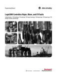
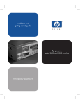
GuardLogix Data Flow
Capabilities
This illlustration explains the standard and safety data flow capabilities
of the GuardLogix controller
Data Flow Capabilities
GuardLogix Controller
Standard
Safety
Safety Task
Standard Tasks
Safety Programs
Standard Programs
Safety Routines
Standard Routines
Program Safety Data
Program Data
Controller Standard Tags
Controller Safety Tags
1
Standard tags and logic behave the same way they do in the ControlLogix platform.
2
Standard tag data, either program- or controller-scoped, can be exchanged with
external HMI devices, personal computers, and other controllers.
3
GuardLogix controllers are integrated controllers with the ability to move (map)
standard tag data into safety tags for use within the safety task.
ATTENTION
This data must not be used to directly control a SIL 3 output.
4
Controller-scoped safety tags can be read directly by standard logic.
5
Safety tags can be read or written by safety logic.
6
Safety tags can be exchanged between GuardLogix controllers over Ethernet or
ControlNet networks.
7
Safety tag data, either program- or controller-scoped, can be read by external
devices, such as HMI devices, personal computers, or other standard controllers.
IMPORTANT
Io
Publication 1756-UM020C-EN-P - December 2006
Once this data is read, it is considered standard data, not SIL 3
data.
GuardLogix System Overview
Select GuardLogix System
Hardware
17
The GuardLogix controller is made up of a primary controller
(1756-L6xS) and a safety partner (1756-LSP), which function together
in a 1oo2 architecture. The GuardLogix system supports SIL 3 and
CAT 4 safety applications.
The safety partner must be installed in the slot immediately to the
right of the primary controller. The firmware major and minor
revisions of the primary controller and safety partner must match
exactly to establish the control partnership required for safety
applications.
Primary Controller
The primary controller, catalog number 1756-L6xS, is the processor
that performs standard and safety functions and communicates with
the safety partner for safety-related functions in the GuardLogix
control system. Standard functions include:
•
•
•
•
•
•
•
•
I/O control
Logic
Timing
Counting
Report generation
Communications
Arithmetic Computations
Data file manipulation
The primary controller consists of a central processor, I/O interface,
and memory. Two catalog numbers are available.
Memory Capacity
User Memory (RAM Capacity)
Catalog
Number
Standard Tasks and Components
Safety Task and Components
1756-L61S
2 MB
1 MB
1756-L62S
4 MB
1 MB
The GuardLogix controller does not support OS upgrades or user
program storage and retrieval using CompactFlash. However, in
version 16 of RSLogix 5000 software, you will be able to view the
contents of a CompactFlash card, if one is installed in the primary
controller.
Publication 1756-UM020C-EN-P - December 2006
18
GuardLogix System Overview
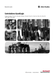
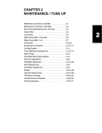
A three-position keyswitch on the front of the primary controller
governs the controller operational modes. The following modes are
available:
• RUN
• PROGram
• REMote - this software-enabled mode can be Program, Run, or
Test
RUN
I/O
FORCE
RS232
BAT
RUN
OK
REM
PROG
Safety Partner
The safety partner, catalog number 1756-LSP, is a coprocessor that
provides redundancy for safety-related functions in the system.
The safety partner does not have a keyswitch or RS-232
communications port. Its configuration and operation are controlled
by the primary controller.
The GuardLogix Controller Installation Instructions, publication
1756-IN045, provides detailed information on installing the primary
controller and safety partner.
Chassis
The chassis provides physical connections between modules and the
GuardLogix controller.
Chassis Catalog Numbers
Publication 1756-UM020C-EN-P - December 2006
Catalog Number
Available Slots
1756-A4
1756-A7
1756-A10
1756-A13
1756-A17
4
7
10
13
17
Series Refer to These Installation
Instructions
B
1756-IN080
GuardLogix System Overview
19
Power Supply
These ControlLogix power supplies are suitable for use in SIL 3
applications. No extra configuration or wiring is required for SIL 3
operation of the power supplies.
Power Supply Catalog Numbers
Catalog
Number
1756-PA72
1756-PB72
1756-PA75
1756-PB75
1756-PA75R(1)
Description
Power supply, ac
Power supply, dc
Power supply, ac
Power supply, dc
Power supply, ac (redundant)
1756-PB75R(1) Power supply, dc (redundant)
Series
Refer to These
Installation Instructions
C
1756-IN596
B
A
1756-IN573
(1) A 1756-PSCA or 1756-PSCA2 redundant power supply chassis adapter is required for use with redundant
power supplies.
Select Safety I/O
Safety input and output devices can be connected to CIP Safety I/O
on DeviceNet networks, allowing output devices to be controlled by
the GuardLogix controller system via DeviceNet Safety
communications.
For the most up-to-date information on available CIP Safety I/O
catalog numbers, certified series and firmware revisions, see
http://ab.com/certification/safety.
Select Communication
Networks
The GuardLogix controller supports communication that lets it:
• distribute and control safety I/O on DeviceNet networks. The
1756-DNB DeviceNet module provides the interface between
the GuardLogix controller and DeviceNet devices.
• distribute and control remote safety I/O on DeviceNet networks
via Ethernet or ControlNet networks.
• produce and consume safety tag data between GuardLogix
controllers across an Ethernet/IP or ControlNet network or
within the same ControlLogix chassis. 1756-ENBT modules
provide a communication bridge between controllers on the
EtherNet/IP network. 1756-CN2 modules provide a
communication bridge between controllers on the ControlNet
network.
• access RSLogix 5000 programming software via a serial
connection or an 1756-ENBT module or 1756-CNB module.
• support standard ControlNet communications.
Publication 1756-UM020C-EN-P - December 2006
20
GuardLogix System Overview
Additional Resources
Programming Requirements
Resource
Description
DeviceNet Modules in Logix5000 Control
Systems User Manual, publication
DNET-UM004
Contains information on configuring a
DeviceNet network, communicating with
devices over the DeviceNet network,
troubleshooting, and optimizing network
performance
EtherNet/IP Modules in Logix5000 Control
Systems User Manual, publication
ENET-UM001
Contains information on configuring the
1756-ENBT module, interlocking and data
transfer between controllers on the
EtherNet/IP network, managing
connections, and diagnostics
ControlNet Modules in Logix5000 Control
Systems User Manual, publication
CNET-UM001
Provides information on using the 1756-CN2
module
RSLogix 5000 software, version 14 and version 16 and later, is the
programming tool for GuardLogix controller applications. RSLogix
5000, version 15, does not support Safety Integrity Level (SIL) 3.
Programs scheduled under the safety task support only ladder logic.
TIP
In RSLogix 5000 software, version 14, programs scheduled
under the safety task, as well as programs in standard tasks,
support only ladder logic.
The RSLogix 5000 software, version 16 safety task does not support
the following items, but they are supported in version 16 standard
tasks within a GuardLogix project:
•
•
•
•
•
•
•
•
Function block diagrams (FBD)
Sequential function chart (SFC) routines
Structured text
Integrated motion
Event tasks
Equipment phase routines
Add-on instructions
Alarms and events
Safety projects do not support redundancy.
Safety routines include safety instructions, which are a subset of the
standard ladder logic instruction set, and safety application
instructions.
Publication 1756-UM020C-EN-P - December 2006
GuardLogix System Overview
21
Refer to Chapter 5 of this manual and the GuardLogix Controller
Systems Safety Reference Manual, publication 1756-RM093, for
information on developing safety applications.
Additional Resources
Resource
Description
GuardLogix Controller Systems Safety
Reference Manual, publication
1756-RM093
Provides a list of the Safety Application
instructions and the subset of standard
ladder logic instructions that are approved
for safety applications. Also contains more
information on developing safety
applications
GuardLogix Safety Application Instruction
Set Reference Manual, publication
1756-RM095
Provides detailed information on the safety
application instructions
Logix5000 General Instruction Set
Reference Manual, publication
1756-RM003
Provides details on the standard Logix
instructions
Publication 1756-UM020C-EN-P - December 2006
22
GuardLogix System Overview
Publication 1756-UM020C-EN-P - December 2006
Chapter
2
Configure the GuardLogix Controller
Introduction
Topic
Create a New Controller
Page
Create a New Controller
23
Set Passwords for Safety-locking and -unlocking
26
Handle I/O Module Replacement
27
Select the CST Master
27
Configure Project to Controller Matching
28
Configure a Peer Safety Controller
29
To configure and program a GuardLogix controller, use RSLogix 5000
software to create and manage a project for the controller.
1. Create a new project in RSLogix 5000 software by clicking the
New button on the main toolbar.
2. Select a GuardLogix controller from the Type pull-down menu.
• 1756-L61S ControlLogix 5561S Controller
• 1756-L62S ControlLogix 5562S Controller.
3. Enter the major revision of firmware for the controller.
23
Publication 1756-UM020C-EN-P - December 2006
24
Configure the GuardLogix Controller
4. Type a name for the controller.
When you create a project, the project name is the same as the
name of the controller. However, you can rename either the
project or the controller.
5. Select the chassis size.
6. Enter the slot number of the controller.
The New Controller dialog displays the slot location of the safety
partner based on the slot number entered for the primary
controller.
If you select a slot number for the primary controller that does
not accommodate placement of the safety partner immediately
to the right of the primary controller, you will be prompted to
re-enter a valid slot number.
7. Specify the folder in which to store the safety controller project.
8. Click OK.
RSLogix 5000 software automatically creates a safety task and a safety
program.
A main ladder logic safety routine called MainRoutine is also created
within the safety program.
A red bar under the folder icon distinguishes safety components from
standard components in the RSLogix 5000 Controller Organizer.
Publication 1756-UM020C-EN-P - December 2006
Configure the GuardLogix Controller
25
When a new safety project is created, RSLogix 5000 software also
automatically creates a time-based safety network number (SNN).
This SNN defines the local chassis backplane as a safety subnet. It can
be viewed and modified via the General tab on the Controller
Properties dialog.
For most applications, this automatic, time-based SNN is sufficient.
However, there are cases in which you might want to enter a specific
SNN.
Safety Network Number
TIP
You can use the Controller Properties dialog to change the
controller from standard to safety or vice versa by clicking
Change Controller. However, standard and safety projects are
substantially affected.
See Appendix C, Change Controllers, for details on the
ramifications of changing controllers.
Additional Resources
Resource
Description
Chapter 5, Develop Safety Applications.
Contains more information on the safety
task, safety programs, and safety routines
Chapter 3, Communicate Over Networks
Provides more information on managing the
SNN
Publication 1756-UM020C-EN-P - December 2006
26
Configure the GuardLogix Controller
Set Passwords for
Safety-locking and
-unlocking
Safety-locking the controller protects safety control components from
modification. Only safety components, such as the safety task, safety
programs, safety routines, and safety tags are affected. Standard
components are unaffected. You can safety-lock or -unlock the
controller project either online or offline.
The safety-lock and -unlock feature uses two separate passwords.
Passwords are optional.
Follow these steps to set passwords:
1. From the Tools > Safety menu, choose Change Password.
2. From the What Password pull-down menu, choose either Safety
Lock or Safety Unlock.
3. Type the old password, if one exists.
4. Type and confirm the new password.
5. Click OK.
Passwords may be from 1 to 40 characters in length and are not
case-sensitive. Letters, numerals, and the following symbols may
be used: ‘ ~ ! @ # $ % ^ & * ( ) _ + , - = { } | [ ] \ : ; ? / .
Publication 1756-UM020C-EN-P - December 2006
Configure the GuardLogix Controller
Handle I/O Module
Replacement
27
The Safety tab of the Controller Properties dialog lets you define how
the controller handles the replacement of an I/O module in the
system. This option determines whether the controller sets the safety
network number (SNN) of an I/O module to which it has a connection
and for which it has configuration data when a safety signature(1)
exists.
ATTENTION
Enable the Configure Always feature only if the entire routable
CIP Safety Control System is not being relied on to maintain
SIL 3 during the replacement and functional testing of a
module.
See Replace a CIP Safety I/O Module on page 59 for more
information.
Select the CST Master
One device in the local chassis must be designated as the coordinated
system time (CST) master. The CST master is usually a GuardLogix
controller or another ControlLogix controller.
IMPORTANT
If a CST master does not exist, a nonrecoverable safety fault
will occur when the controller is put into Run mode.
See GuardLogix Controller Faults on page 102 for more
information on faults.
(1) The safety signature is a number used by the GuardLogix system to uniquely identify each project’s logic, data,
and configuration, thereby protecting the system’s safety integrity level (SIL). See Safety Signature on page 14
and Generate a Safety Signature on page 81 for more information.
Publication 1756-UM020C-EN-P - December 2006
28
Configure the GuardLogix Controller
You can set the controller as the CST master using the Date/Time tab
on the Controller Properties dialog.
When online, this tab also indicates whether the controller is
synchronized with a CST master.
Configure Project to
Controller Matching
RSLogix 5000 software, version 14 and later, lets you link your project
to a specific controller, for the purposes of going online,
downloading, and uploading. If you enable this option, each time you
initiate one of these activities, RSLogix 5000 software checks that the
serial number configured in the project matches the serial number of
the controller to which it is connected.
To enable this feature, check the Match Project to Controller option on
the Advanced tab of the Controller Properties dialog and enter your
controller’s eight digit, hexidecimal serial number, found on the
controller label.
Publication 1756-UM020C-EN-P - December 2006
Configure the GuardLogix Controller
Configure a Peer Safety
Controller
29
You can add a peer safety controller to the I/O configuration folder of
your GuardLogix safety project to allow standard or safety tags to be
consumed.
The peer GuardLogix safety controller is subject to the same
configuration requirements as the local GuardLogix safety controller.
The peer safety controller must also have a safety network number
(SNN). The SNN of the peer safety controller depends upon its
placement in the system.
SNN and Controller Placement
Peer Safety Controller Location
SNN
Placed in the local chassis
GuardLogix controllers located in a common
chassis should have the same SNN.
Placed in a different chassis
The controller must have a unique SNN.
To share safety data between peer controllers, you produce and
consume controller-scoped safety tags. Produced/consumed safety tag
pairs must be of the same data type. To share data between peer
safety controllers, the following additional requirements must be met:
• The SNN entered on the producer controller’s Module Properties
dialog in the consumer’s safety project must match the SNN that
is configured in the producer controller’s project, as shown on
the producer controller’s Controller Properties dialog.
Producer Controller Properties Dialog in Consumer Project
Producer Controller Properties in Producer Project
Publication 1756-UM020C-EN-P - December 2006
30
Configure the GuardLogix Controller
TIP
An SNN can be copied and pasted using the buttons on
the Safety Network Number dialog. Open the respective
Safety Network Number dialogs by clicking
to the
right of the SNN fields in the properties dialogs.
• For produced and consumed safety tags, you must create a
user-defined data type. The first member of the tag structure
must be a predefined data type called CONNECTION_STATUS.
• The requested packet interval (RPI) of the consumed safety tag
must match the safety task period of the producing safety
project.
Consumer’s Project
Publication 1756-UM020C-EN-P - December 2006
Producer’s Project
Configure the GuardLogix Controller
31
Set the RPI via the Safety tab on the Consumed Tag Connection
dialog. To open this dialog, right-click the consumed tag and
choose Edit.
TIP
In RSLogix 5000 software, version 16, the default Safety
Task RPI was changed from 10 ms to 20 ms.
To view or edit the safety task period, right-click the producing
safety task and choose Properties. Then, choose the
Configuration tab.
Additional Resources
Resource
Description
Chapter 5, Develop Safety Applications
Contains more information on the safety
task period and on configuring
produced/consumed tags
Safety Connections on page 100
Provides more information on the
CONNECTION_STATUS data type
Logix5000 Controllers Common Procedures
Programming Manual, publication
1756-PM001
Contains more information on producing
and consuming tags and on creating
user-defined data types
Publication 1756-UM020C-EN-P - December 2006
32
Configure the GuardLogix Controller
Publication 1756-UM020C-EN-P - December 2006
Chapter
3
Communicate Over Networks
Introduction
Topic
The Safety Network
Page
The Safety Network
33
EtherNet/IP Communications
39
ControlNet Communications
43
DeviceNet Communications
46
Serial Communications
48
The CIP Safety protocol is an end-node to end-node safety protocol
that allows routing of CIP Safety messages to and from CIP Safety
devices through bridges, switches, and routers.
To maintain high integrity when routing through standard bridges,
switches, or routers, each end node within a routable CIP Safety
Control System must have a unique reference. This unique reference
is a combination of a safety network number (SNN) and the node
address of the network device.
Manage the Safety Network Number (SNN)
The SNN assigned to safety devices on a network segment must be
unique. You must be sure that a unique SNN is assigned to:
• all safety devices on each DeviceNet network. All safety devices
on a DeviceNet subnet can have the same SNN.
• each chassis that contains one or more GuardLogix controllers.
TIP
Multiple safety network numbers can be assigned to a CIP
Safety subnet or a ControlBus chassis that contains more than
one safety device. However, for simplicity, we recommend that
each CIP Safety subnet have one, and only one, unique SNN.
The SNN can be either software-assigned (time-based) or
user-assigned (manual). These two formats of the SNN are described
in the following sections.
33
Publication 1756-UM020C-EN-P - December 2006
34
Communicate Over Networks
Time-based Safety Network Number
If the time-based format is selected, the SNN value that is generated
represents the date and time at which the number was generated,
according to the personal computer running the configuration
software.
Manual Safety Network Number
If the manual format is selected, the SNN represents entered values
from 1 through 9999 decimal.
Assign the Safety Network Number (SNN)
You can allow RSLogix 5000 software to automatically assign an SNN,
or you can assign the SNN manually.
Publication 1756-UM020C-EN-P - December 2006
Communicate Over Networks
35
Automatic Assignment
When a new controller or module is created, a time-based SNN is
automatically assigned via the configuration software. Subsequent
new safety-module additions to the same CIP Safety network are
assigned the same SNN defined within the lowest node address on
that CIP Safety network.
Manual Assignment
The manual option is intended for routable CIP Safety systems where
the number of DeviceNet subnets and interconnecting networks is
small, and where users might like to manage and assign the SNN in a
logical manner pertaining to their specific application.
See Change the Safety Network Number (SNN) on page 35.
IMPORTANT
If you assign an SNN manually, take care to ensure that system
expansion does not result in duplication of SNN and node
address combinations.
Automatic Versus Manual
For typical users, the automatic assignment of an SNN is sufficient.
However, manual manipulation of the SNN is required:
• if safety consumed tags are used.
• if the project will consume safety input data from a module
whose configuration is owned by some other device.
• if a safety project is copied to a different hardware installation
within the same routable CIP Safety system.
Change the Safety Network Number (SNN)
Before changing the SNN you must:
• unlock the project, if it is safety-locked.
See Safety-lock the Controller on page 79.
• delete the safety signature, if one exists.
See Delete the Safety Signature on page 82.
Publication 1756-UM020C-EN-P - December 2006
36
Communicate Over Networks
Change the Safety Network Number (SNN) of the Controller
1. In the Controller Organizer, right-click the GuardLogix controller
and choose Properties.
2. On the General tab of the Controller Properties dialog, click
to the right of the safety network number to open the Safety
Network Number dialog.
3. Choose Time-based and click Generate.
4. Click OK.
Publication 1756-UM020C-EN-P - December 2006
Communicate Over Networks
37
Change the Safety Network Number (SNN) of Safety I/O Modules on the CIP
Safety Network
This example uses the DeviceNet network.
1. Find the first DeviceNet Scanner (1756-DNB) module in the I/O
Configuration tree.
2. Expand the I/O modules available through the 1756-DNB.
3. Double-click the first safety I/O module to view the General tab.
4. Click
to the right of the safety network number to open the
Safety Network Number dialog.
5. Choose Time-based and click Generate to generate a new SNN
for that DeviceNet network.
6. Click OK.
7. Click Copy to copy the new SNN to the Windows Clipboard.
8. Open the General Tab of the Module Properties dialog of the
next safety I/O module under that 1756-DNB module.
9. Click
to the right of the safety network number to open the
Safety Network Number dialog.
10. Choose Time-based and click Paste to paste that DeviceNet
network’s SNN into that device.
Publication 1756-UM020C-EN-P - December 2006
38
Communicate Over Networks
11. Click OK.
12. Repeat Steps 8, 9, and 10 for the remaining safety I/O modules
under that 1756-DNB module.
13. Repeat Steps 2 through 10 for any remaining 1756-DNB modules
under the I/O Configuration tree.
Copy and Paste an Safety Network Number (SNN)
If the module’s configuration is owned by a different controller, you
may need to copy and paste the SNN from the configuration owner
into the module in your I/O configuration tree.
1. In the software configuration tool of the module’s configuration
owner, open the Safety Network Number dialog for the module.
2. Click Copy.
3. Go to the General tab on the Module Properties dialog of the
I/O module in the I/O Configuration tree of the consuming
controller project.
This consuming controller is not the configuration owner.
4. Click
to the right of the safety network number to open the
Safety Network Number dialog.
5. Click Paste.
6. Click OK.
Publication 1756-UM020C-EN-P - December 2006
Communicate Over Networks
EtherNet/IP
Communications
39
For EtherNet/IP communications, choose either a 1756-ENBT or
1756-EWEB module.
If your application
•
•
•
•
•
Select
controls I/O modules.
requires an adapter for distributed I/O on EtherNet/IP links.
communicates with other EtherNet/IP devices (messages).
shares data with other Logix5000 controllers (produce/consume).
bridges EtherNet/IP links to route messages to devices on other
networks.
• requires remote access via Internet browser to tags in a local
ControlLogix controller.
• communicates with other EtherNet/IP devices (messages).
• bridges EtherNet/IP links to route messages to devices on other
networks.
• does not support I/O or produced/consumed tags.
1756-ENBT
1756-EWEB
In addition to communication hardware for EtherNet/IP networks,
these software products are available.
Software for EtherNet/IP Modules
Software
Purpose
RSLogix 5000 Programming
Software
This software is required to configure the GuardLogix
project and define EtherNet/IP communications.
BOOTP/DHCP Utility
This utility comes with RSLogix 5000 software. You can
use this utility to assign IP addresses to devices on an
EtherNet/IP network.
RSNetWorx for EtherNet/IP
Software
You can use this software to configure EtherNet/IP devices
by IP addresses and/or host names
The EtherNet/IP communication modules:
• support messaging, produced/consumed tags, HMI, and
distributed I/O.
• support CIP Safety communications.
• encapsulate messages within standard TCP/UDP/IP protocol.
• share a common application layer with ControlNet and
DeviceNet networks.
• interface via RJ45, category 5, unshielded, twisted-pair cable.
• support half/full duplex 10 Mbps or 100 Mbps operation.
• support standard switches.
• require no network scheduling.
• require no routing tables.
Publication 1756-UM020C-EN-P - December 2006
40
Communicate Over Networks
Produce and Consume Data via the EtherNet/IP Network
The GuardLogix controller supports the ability to produce (broadcast)
and consume (receive) system-shared tags over the EtherNet/IP
network. Produced and consumed tags each require connections. The
total number of tags that can be produced or consumed is limited by
the number of available connections.
Connections Over the EtherNet/IP Network
You indirectly determine the number of connections the controller
uses by configuring the controller to communicate with other devices
in the system. Connections are allocations of resources that provide
more reliable communications between devices compared to
unconnected messages (message instructions).
All EtherNet/IP connections are unscheduled. An unscheduled
connection is triggered by the requested packet interval (RPI) for I/O
control or the program (such as a MSG instruction). Unscheduled
messaging lets you send and receive data when needed.
The 1756 EtherNet/IP communication modules support 128 Common
Industrial Protocol (CIP) connections over an EtherNet/IP network.
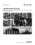
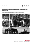
EtherNet/IP Communication Example
In this example:
• the controllers can produce and consume standard or safety tags
between each other.
• the controllers can initiate MSG instructions that send/receive
standard data or configure devices.
• the 1756-ENBT module can be used as a bridge, letting the
GuardLogix controller produce and consume standard and
safety data to and from I/O devices.
• the personal computer can upload/download projects to the
controllers.
• the personal computer can configure devices on the EtherNet/IP
network.
Publication 1756-UM020C-EN-P - December 2006
Communicate Over Networks
41
EtherNet/IP Communication Example
FlexLogix controller with
1788-ENBT module
Distibuted I/O
GuardLogix controller
with 1756-ENBT
module
1756-ENBT module
(as an adapter) with
1756 I/O modules
CompactLogix controller
with integrated
EtherNet/IP port
1756-DNB module for remote
DeviceNet communication
to standard or safety
devices on DeviceNet
network
1794-AENT adapter with
1794 I/O modules
switch
1734-AENT adapter with
1734 I/O modules
PowerFlex 700S AC
drive with DriveLogix
workstation
EtherNet/IP Modules in a GuardLogix System
To use an EtherNet/IP module with the GuardLogix controller, you
must configure the module’s communication parameters, add the
module to the GuardLogix controller project, and download the
project to the GuardLogix controller.
Publication 1756-UM020C-EN-P - December 2006
42
Communicate Over Networks
Configure the EtherNet/IP Module
To configure the module, define the IP address, subnet mask, and
gateway.
EtherNet/IP Parameters
EtherNet/IP
Parameter
Description
IP Address
The IP address uniquely identifies the module. The IP address is in
the form xxx.xxx.xxx.xxx. where each xxx is a number between 0 and
255. The following reserved values cannot be used:
• 127.0.0.1
• 0.0.0.0
• 255.255.255.255
Subnet Mask
Subnet addressing is an extension of the IP address scheme that
allows a site to use a single network ID for multiple physical
networks. Routing outside of the site continues by dividing the IP
address into a net ID and a host ID via the class. Inside a site, the
subnet mask is used to redivide the IP address into a custom network
ID portion and host ID portion. This field is set to 0.0.0.0 by default.
If you change the subnet mask of an already-configured module, you
must cycle power for the change to take effect.
Gateway
A gateway connects individual physical networks into a system of
networks. When a node needs to communicate with a node on
another network, a gateway transfers the data between the two
networks. This field is set to 0.0.0.0 by default.
Add the Module to the Project
After you physically install an EtherNet/IP module and set its IP
address, you must add the module to the Controller Organizer in your
GuardLogix controller project.
Download the Project
Use RSLogix 5000 software to download the project. When the
controller begins operation, it establishes connections with the
EtherNet/IP modules.
Publication 1756-UM020C-EN-P - December 2006
Communicate Over Networks
43
Additional Resources
ControlNet
Communications
Resource
Description
Chapter 5, Develop Safety Applications
Provides information on configuring
produced and consumed safety tags
EtherNet/IP Modules in Logix5000 Control
Systems User Manual, publication
ENET-UM001
Contains guidelines and specific details on
interlocking and data transfer between
controllers on the EtherNet/IP network
using the 1756-ENBT module
EtherNet/IP Web Server Module User
Manual, publication ENET-UM527
Provides information on using the
1756-EWEB module
Logix5000 Controllers Common Procedures
Programming Manual, publication
1756-PM001
Contains more information on how to
produce and consume tags between
controllers
Logix5000 Controllers Design
Considerations Reference Manual,
publication 1756-RM094
Provides guidelines on optimizing a control
application on an EtherNet/IP network
For ControlNet communications, choose a 1756-CNB or 1756-CNBR
module for standard communications, or a 1756-CN2 module for
safety communications.
If your application
Select
•
•
•
•
controls standard I/O modules.
requires an adapter for distributed I/O on ControlNet links.
communicates with other ControlNet devices (messages).
shares standard data with other Logix5000 controllers
(produce/consume).
• bridges ControlNet links to route messages to devices on other
networks.
1756-CNB
• performs same functions as a 1756-CNB.
• also supports redundant ControlNet media.
1756-CNBR
• performs the same functions supported by the 1756-CNB
module with higher performance.
• supports CIP Safety communication.
1756-CN2
In addition to communication hardware for ControlNet networks,
these software products are available.
Software for ControlNet Modules
Software
Purpose
RSLogix 5000 Programming
Software
This software is required to configure the GuardLogix
project and define ControlNet communications.
RSNetWorx for ControlNet
Software
This software is required to configure the ControlNet
network, define the network update time (NUT), and
schedule the ControlNet network.
Publication 1756-UM020C-EN-P - December 2006
44
Communicate Over Networks
The ControlNet communications modules:
• support messaging, produced/consumed safety and standard
tags, and distributed I/O.
• support the use of coax and fiber repeaters for isolation and
increased distance.
Produce and Consume Data via the ControlNet Network
The GuardLogix controller supports the ability to produce (broadcast)
and consume (receive) system-shared tags over the ControlNet
network. Produced and consumed tags each require connections. The
total number of tags that can be produced or consumed is limited by
the number of available connections in the GuardLogix controller.
Connections Over the ControlNet Network
You indirectly determine the number of connections the controller
uses by configuring the controller to communicate with other devices
in the system. Connections are allocations of resources that provide
more reliable communications between devices compared to
unconnected messages.
ControlNet connections can be either scheduled or unscheduled.
ControlNet Connections
Connection Type
Description
Scheduled
(unique to the
ControlNet network)
A scheduled connection is unique to ControlNet communications. A scheduled connection
lets you send and receive data repeatedly at a predetermined interval, which is the
requested packet interval (RPI). For example, a connection to an I/O module is a scheduled
connection because you repeatedly receive data from the module at a specified interval.
Other scheduled connections include connections to:
• communication devices.
• produced/consumed tags.
On a ControlNet network, you must use RSNetWorx for ControlNet software to enable all
scheduled connections and establish a network update time (NUT). Scheduling a
connection reserves network bandwidth to specifically handle the connection.
Unscheduled
An unscheduled connection is a message transfer between controllers that is triggered by
the requested packet interval (RPI) or the program (such as a MSG instruction).
Unscheduled messaging lets you send and receive data when needed.
Unscheduled connections use the remainder of network bandwidth after scheduled
connections are allocated.
Safety produced/consumed connections are unscheduled.
Publication 1756-UM020C-EN-P - December 2006
Communicate Over Networks
45
The 1756-CNB and 1756-CNBR communication modules support 64
CIP connections over a ControlNet network.
The 1756-CN2 module supports 100 CIP connections over the
ControlNet network. However, we recommend that you configure
only 97 connections for each module to maintain optimal
performance.
ControlNet Communication Example
In this example:
• GuardLogix controllers can produce and consume standard or
safety tags between each other.
• GuardLogix controllers can initiate MSG instructions that
send/receive standard data or configure devices.
• the 1756-CN2 module can be used as a bridge, letting the
GuardLogix controller produce and consume standard and
safety data to and from I/O devices.
• the personal computer can upload/download projects to the
controllers.
• the personal computer can configure devices on the ControlNet
network, and it can configure the network itself.
ControlNet Communication Example
Personal Computer/Workstation
PowerFlex 700S AC
Drive with DriveLogix
GuardLogix Controller
with 1756-CN2 Module
Distributed I/O
1756-CN2 Module
(as an Adapter) with
1756 I/O Modules
1756-DNB Module
to DeviceNet Network
with CIP Safety I/O
ControlNet
GuardLogix
Controller
with
1756-DNB
module
PanelView Terminal
to DeviceNet Network
with CIP Safety I/O
PLC-5/40C Controller
1794-ACN15 Adapter
with 1794 I/O Modules
1734-ACNR Adapter with
1734 I/O Modules
Publication 1756-UM020C-EN-P - December 2006
46
Communicate Over Networks
Additional Resources
Resource
Description
ControlNet Modules in Logix5000 Control
Systems User Manual, publication
CNET-UM001
Contains information on how to:
• configure a ControlNet communication
module.
• control I/O over the ControlNet network.
• send a message over the ControlNet
network.
• produce/consume a tag over the
ControlNet network.
• calculate controller connections over the
ControlNet network
Logix5000 Controllers Design
Considerations Reference Manual,
publication 1756-RM094
DeviceNet Communications
Provides guidelines on optimizing a control
application on a ControlNet network
To communicate and exchange data with CIP Safety I/O modules on
DeviceNet networks, you need a 1756-DNB module in the local
chassis.
For information on how to install your 1756-DNB module, refer to the
ControlLogix DeviceNet Scanner Module Installation Instructions,
publication 1756-IN566.
The 1756-DNB module supports communication with DeviceNet
Safety devices and standard DeviceNet devices. You can use both
types.
DeviceNet Safety Connections
To access CIP Safety devices on DeviceNet networks, add a 1756-DNB
to the I/O Configuration tree of the GuardLogix controller project.
Publication 1756-UM020C-EN-P - December 2006
Communicate Over Networks
47
CIP Safety I/O modules on
DeviceNet networks are added to
the project under the 1756-DNB
module, as described in Chapter 4,
Add, Configure, Monitor, and
Replace CIP Safety I/O on
DeviceNet Networks. When you
add a CIP Safety I/O module,
RSLogix 5000 software
automatically creates
controller-scoped safety data tags
for that module.
Standard DeviceNet
Connections
If you use standard DeviceNet I/O with your GuardLogix controller,
you will need to allocate two connections for each 1756-DNB module.
One connection is for module status and configuration. The other
connection is a rack-optimized connection for the DeviceNet I/O data.
To use the 1756-DNB module to access standard data via the
DeviceNet network, you must use RSNetWorx for DeviceNet software
to:
•
•
•
•
create a configuration file for the network.
configure each standard device on the network.
configure the 1756-DNB.
add the standard I/O devices to the 1756-DNB scan list.
When you add the 1756-DNB module to the I/O Configuration of the
controller, RSLogix 5000 software automatically creates a set of
standard tags for the input, output, and status data of the network.
Additional Resources
Resource
Description
Chapter 4, Add, Configure, Monitor, and
Replace CIP Safety I/O on DeviceNet
Networks
Provides more information on DeviceNet
Safety I/O and addressing Safety I/O data
DeviceNet Modules in Logix5000 Control
Systems User Manual, publication
DNET-UM004
Contains detailed information on
configuring and using the 1756-DNB in a
Logix5000 control system
Publication 1756-UM020C-EN-P - December 2006
48
Communicate Over Networks
Serial Communications
To operate the GuardLogix controller on a serial network, you need:
• a workstation with a serial port.
• RSLinx software to configure the serial communication driver.
• RSLogix 5000 software to configure the serial port of the
controller.
For the controller to communicate to a workstation or other device
over the serial network, you must:
1. Configure the serial communication driver for the workstation.
2. Configure the serial port of the controller.
Serial Communication Modes
Use this mode
For
DF1 Point-to-point
Communication between the controller and one other
DF1-protocol-compatible device.
This is the default System mode.
This mode is typically used to program the controller through its
serial port.
DF1 Master
Control of polling and message transmission between the master
and slave nodes.
The master/slave network includes one controller configured as the
master node and as many as 254 slave nodes. Link slave nodes
using modems or line drivers.
A master/slave network can have node numbers from 0…254. Each
node must have a unique node address. Also, at least 2 nodes must
exist to define your link as a network (1 master and 1 slave station
are the two nodes).
DF1 Slave
Using a controller as a slave station in a master/slave serial
communication network.
When there are multiple slave stations on the network, link slave
stations using modems or line drivers to the master. When you have
a single slave station on the network, you do not need a modem to
connect the slave station to the master. You can configure the
control parameters for no handshaking. You can connect 2…255
nodes to a single link. In DF1 slave mode, a controller uses DF1
half-duplex protocol.
One node is designated as the master and it controls who has
access to the link. All the other nodes are slave stations and must
wait for permission from the master before transmitting.
DH-485
Publication 1756-UM020C-EN-P - December 2006
Communicating with other DH-485 devices multi-master, token
passing network allowing programming and peer-to-peer
messaging.
Chapter
4
Add, Configure, Monitor, and Replace
CIP Safety I/O on DeviceNet Networks
Introduction
Topic
Page
Add CIP Safety I/O Modules
49
Configure CIP Safety I/O Modules via RSLogix 5000 Software
50
Set the Safety Network Number (SNN)
51
Set the Connection Reaction Time Limit
52
Understand the Configuration Signature
56
Reset Safety I/O Module Ownership
57
Address Safety I/O Data
57
Monitor Safety I/O Module Status
58
Replace a CIP Safety I/O Module
59
For more information on installation, configuration, and operation of
CIP Safety I/O on DeviceNet networks, refer to the DeviceNet Safety
I/O User Manual, publication 1791DS-UM001.
Add CIP Safety I/O Modules
When you add a module to the system, you must define a specific
configuration for the module, including:
• Node address
You cannot set the node address of an CIP Safety I/O module on
DeviceNet networks via RSLogix 5000 software. Module node
addresses are set via rotary switches on the modules.
For information on how to set the node address, refer to the
DeviceNet Safety I/O User Manual, publication 1791DS-UM001.
• Safety network number (SNN)
See page 51 for information on setting the SNN.
• Configuration signature
See page 56 for information on when the configuration signature
is set automatically and when you need to set it.
49
Publication 1756-UM020C-EN-P - December 2006
50
Add, Configure, Monitor, and Replace CIP Safety I/O on DeviceNet Networks
• Reaction time limit
See page 52 or refer to the DeviceNet Safety I/O User Manual,
publication 1791DS-UM001, for information on setting the
reaction time limit.
• Safety input, output, and test parameters
Refer to the DeviceNet Safety I/O User Manual, publication
1791DS-UM001, and to RSLogix 5000 online help for more
information on configuring these parameters.
You can configure CIP Safety I/O modules on DeviceNet networks via
the GuardLogix controller using RSLogix 5000 software.
TIP
Safety I/O modules support standard as well as safety data.
Module configuration defines what data is available.
Refer to the DeviceNet Safety I/O User Manual, publication
1791DS-UM001, for details.
Configure CIP Safety I/O
Modules via RSLogix 5000
Software
To communicate with a CIP Safety I/O module in your system, you
add the module to the 1756-DNB under the I/O Configuration folder
of the RSLogix 5000 project.
TIP
You cannot add or delete a CIP Safety I/O module on DeviceNet
networks while online.
1. Right-click the DeviceNet network and choose New Module.
2. Expand the Safety category and choose a CIP Safety I/O module.
Publication 1756-UM020C-EN-P - December 2006
Add, Configure, Monitor, and Replace CIP Safety I/O on DeviceNet Networks
51
3. Specify the module properties.
a. Modify the Module Definition settings, if required, by clicking
Change.
b. Type a name for the new module.
c. Enter the node address of the module on its connecting
network.
Only unused node numbers are included in the pull-down
list.
d. Modify the safety network number (SNN), if required, by
clicking the
button.
See page 51 for details.
e. Set module configuration parameters using the Input
Configuration, Test Output, and Output Configuration tabs.
Refer to RSLogix 5000 online help for more information on
CIP Safety I/O module configuration.
f. Set the Connection Reaction Time Limit using the Safety tab.
See page 52 for details.
Set the Safety Network
Number (SNN)
The assignment of a time-based SNN is automatic when adding new
Safety I/O modules. Subsequent safety module additions to the same
DeviceNet network are assigned the same SNN as the node with the
lowest node address on that DeviceNet network.
The CIP Safety I/O module SNN is set in the module the first time that
an out-of-box module is connected to the system and prior to the
safety signature being applied to the controller project.
Publication 1756-UM020C-EN-P - December 2006
52
Add, Configure, Monitor, and Replace CIP Safety I/O on DeviceNet Networks
For most applications, the automatic, time-based SNN is sufficient.
However, there are cases in which manipulation of an SNN is
required.
See Assign the Safety Network Number (SNN) on page 34.
Set the Connection
Reaction Time Limit
The Connection Reaction Time Limit is the maximum age of safety
packets on the associated connection. If the age of the data used by
the consuming device exceeds the Connection Reaction Time Limit, a
connection fault occurs. The Connection Reaction Time Limit is
determined by the following equations:
Input Connection Reaction Time Limit =
Input RPI x [Timeout Multiplier + Network Delay Multiplier]
Output Connection Reaction Time Limit =
Safety Task Period x [Timeout Multiplier + Network Delay Multiplier - 1]
The Connection Reaction Time Limit is shown on the Safety tab of the
Module Properties dialog.
Specify the Requested Packet Interval (RPI)
The RPI specifies the period at which data updates over a connection.
For example, an input module produces data at the RPI that you
assign.
For safety input connections, you can set the RPI on the Safety tab of
the Module Properties dialog. The RPI is entered in 1 ms increments,
with a valid range of 1 through 100 ms and a default of 10 ms.
The Connection Reaction Time Limit is adjusted immediately when the
RPI is changed via RSLogix 5000 software.
Publication 1756-UM020C-EN-P - December 2006
Add, Configure, Monitor, and Replace CIP Safety I/O on DeviceNet Networks
53
For safety output connections, the RPI is fixed at the GuardLogix
safety task period. If the corresponding Connection Time Reaction
Limit is not satisfactory, you can adjust the safety task period via the
Safety Task Properties dialog.
See Safety Task Period Specification on page 66 for more information
on the safety task period.
For simple timing constraints, setting the RPI is usually sufficient. For
more complex requirements, use the Advanced button to set the
Connection Reaction Time Limit parameters, as described on page 54.
Understand the Maximum Observed Network Delay
When the GuardLogix controller receives a safety packet, the software
records the maximum observed transport delay. The Maximum
Observed Network Delay specifies the round-trip delay from the
producer to the consumer and the acknowledge back to the producer.
This Maximum Observed Network Delay value is the result of
capturing the age of the data upon the arrival of the message. The
Maximum Observed Network Delay is shown on the Safety tab of the
Module Properties dialog. When online, you can reset the Maximum
Observed Network Delay by clicking Reset.
IMPORTANT
The actual Maximum Network Delay time from the producer to
the consumer will always be less than the value displayed in
the Maximum Network Delay field on the Safety tab. Since the
CIP Safety time coordination is based on a message from the
producer to the consumer and all calculations are done in a
conservative manner, the actual message delay will be less
than the Maximum Network Delay. In general, the actual
maximum message delay will be approximately one-half the
Maximum Network Delay observed.
Publication 1756-UM020C-EN-P - December 2006
54
Add, Configure, Monitor, and Replace CIP Safety I/O on DeviceNet Networks
Set the Advanced Connection Reaction Time Limit Parameters
Timeout Multiplier
The Timeout Multiplier determines the number of RPIs to wait for a
packet before declaring a connection timeout. This translates into the
number of messages that may be lost before a connection error is
declared.
For example, a Timeout Multiplier of 1 indicates that messages must
be received during every RPI interval. A Timeout Multiplier of 2
indicates that 1 message may be lost as long as at least 1 message is
received in 2 times the RPI (2 x RPI).
Network Delay Multiplier
The Network Delay Multiplier defines the message transport time that
is enforced by the CIP Safety protocol. The Network Delay Multiplier
specifies the round-trip delay from the producer to the consumer and
the acknowledge back to the producer. You can use the Network
Delay Multiplier to reduce or increase the Connection Reaction Time
Limit in cases where the enforced message transport time is
significantly less or more than the RPI. For example, adjusting the
Network Delay Multiplier may be helpful when the RPI of an output
connection is the same as a lengthy safety task period.
For cases where the input RPI or output RPI are relatively slow or fast
as compared to the enforced message delay time, the Network Delay
Multiplier can be approximated using one of the two methods.
Publication 1756-UM020C-EN-P - December 2006
Add, Configure, Monitor, and Replace CIP Safety I/O on DeviceNet Networks
55
Method 1: Use the ratio between the input RPI and the safety task
period. Use this method only under the following conditions:
• if the path or delay is approximately equal to the output path or
delay, and
• the input RPI has been configured so that the actual input
message transport time is less than the input RPI, and
• the safety task period is slow relative to the Input RPI.
Under these conditions, the Output Network Delay Multiplier
can be approximated as follows:
Input Network Delay Multiplier x [Input RPI ÷ Safety Task Period]
EXAMPLE
Calculate the Approximate Output Network
Delay Multiplier
If:
Input RPI = 10 ms
Input Network Delay Multiplier = 200%
Safety Task Period = 20 ms
Then, the Output Network Delay Multiplier equals:
200% x [10 ÷ 20] = 100%
Method 2: Use the Maximum Observed Network Delay. If the system
is run for an extended period of time through its worst-case loading
conditions, the Network Delay Multiplier can be set from the
Maximum Observed Network Delay. This method can be used on an
input or output connection. After the system has been run for an
extended period of time through its worst-case loading conditions,
record the Maximum Observed Network Delay. The Network Delay
Multiplier can be approximated by the following equation:
[Maximum Observed Network Delay + Margin_Factor] ÷ RPI
EXAMPLE
Calculate the Network Delay Multiplier from
Maximum Observed Network Delay
If:
RPI = 50 ms
Maximum Observed Network Delay = 20 ms
Margin_Factor = 10
Then, the Network Delay Multiplier equals:
[20 + 10] ÷ 50 = 60%
Publication 1756-UM020C-EN-P - December 2006
56
Add, Configure, Monitor, and Replace CIP Safety I/O on DeviceNet Networks
Additional Resources
Resource
Description
GuardLogix Controller Systems Safety
Reference Manual, publication
1756-RM093
DeviceNet Safety I/O Users Manual,
publication 1791DS-UM001
Understand the
Configuration Signature
Provides information on calculating reaction
times
Each safety device has a unique configuration signature, which
identifies the module configuration to verify the integrity of
configuration data during downloads, connection establishment, and
module replacement. The configuration signature is composed of an
ID number, a date, and a time.
Configured via RSLogix 5000 Software
When the I/O module is configured using RSLogix 5000 software, the
configuration signature is generated automatically. You can view and
copy the configuration signature via the Safety tab on the Module
Properties dialog.
Different Configuration Owner (Listen Only Connection)
When the I/O module configuration is owned by a different
controller, you need to copy the module configuration signature from
its owner’s project and paste it into the Safety tab of the Module
Properties dialog.
TIP
Publication 1756-UM020C-EN-P - December 2006
If the module is configured for inputs only, you can copy and
paste the configuration signature. If the module has safety
outputs, they are owned by the controller that owns the
configuration, and the configuration signature text box is
unavailable.
Add, Configure, Monitor, and Replace CIP Safety I/O on DeviceNet Networks
Reset Safety I/O Module
Ownership
57
When RSLogix 5000 software is online, the Safety tab of the Module
Properties dialog displays the current configuration ownership. When
the opened project owns the configuration, Local is displayed. When a
second device owns the configuration, Remote is displayed, along
with the safety network number (SNN), and node address or slot
number of the configuration owner. Communication error is displayed
if the module read fails.
When online, you can reset the module to its
out-of-box configuration by clicking Reset
Ownership.
TIP
Address Safety I/O Data
You cannot reset ownership when there are pending edits to
the module properties, when a safety signature exists, or when
safety-locked.
When you add a module to the I/O configuration folder, RSLogix 5000
software automatically creates controller-scoped tags for the module.
I/O information is presented as a set of tags. Each tag uses a structure
of data, depending on the type and features of the I/O module. The
name of a tag is based on its name in the system.
A CIP Safety I/O device on a DeviceNet network follows this format:
Modulename:Type.Member
CIP Safety I/O Module Address Format
Where
Is
Modulename
The name of the CIP Safety I/O module
Type
Type of data
Input Module: I
Output Module: O
Member
Specific data from the I/O module
Input-only
Module:
Modulename:I.RunMode
Modulename:I.ConnectionFaulted
Modulename:I.Input Members
Output-only
Module:
Modulename:I.RunMode
Modulename:I.ConnectionFaulted
Modulename:O.Output Members
Combination
I/O:
Modulename:I.RunMode
Modulename:I.ConnectionFaulted
Modulename:I.Input Members
Modulename:O.Output Members
Publication 1756-UM020C-EN-P - December 2006
58
Add, Configure, Monitor, and Replace CIP Safety I/O on DeviceNet Networks
Additional Resources
Monitor Safety I/O Module
Status
Resource
Description
Chapter 7, Monitor Status and Handle
Faults
Contains information on monitoring safety
tag data
Logix5000 Controllers Common Procedures
Programming Manual, publication
1756-PM001
Provides information on addressing
standard I/O modules
You can monitor system status via the LED indicators on the I/O
modules and via input and output status codes.
Monitor via LED Indicators
LED indicators on the safety I/O modules indicate system status.
LED Indicator Operation
LED
Module Status
(MS)
Color/State
Description
Off
No power.
Green, On
Operating under normal conditions.
Green, Flashing
Device is idle.
Red, Flashing
A recoverable fault exists.
Red, On
An unrecoverable fault exists.
Red/Green, Flashing Self-tests in progress.
Network Status
(NS)
Off
Device is not online or may not have power.
Green, On
Device is online; connections are established.
Green, Flashing
Device is online; no connections established.
Red, Flashing
Communication timeout.
Red, On
Communication failure. The device has
detected an error that has prevented network
communication.
Red/Green, Flashing Device is in Communication Faulted state or
safety network number (SNN) is being set.
Input Points
(INx)
Publication 1756-UM020C-EN-P - December 2006
Off
Safety input is OFF.
Yellow, On
Safety input is ON.
Red, On
An error has occurred in the input circuit.
Red, Flashing
When dual-channel operation is selected, an
error has occurred in the input circuit.
Add, Configure, Monitor, and Replace CIP Safety I/O on DeviceNet Networks
59
LED Indicator Operation
LED
Output Points (Ox)
LOCK
IN PWR
OUT PWR
Color/State
Description
Yellow, Off
Safety output is OFF.
Yellow, On
Safety output is ON.
Red, Flashing
When dual-channel operation is selected, an
error has occurred in the output circuit.
Red, On
An error has occurred in the output circuit.
Yellow, On
Device configuration is locked.
Yellow, Flashing
Device configuration is valid, but device is not
locked.
Yellow, Off
Invalid or no configuration data.
Green, On
Input power normal.
Green, Off
No input power.
Green, On
Output power normal.
Green, Off
No output power or output power exceeds the
upper/lower limit of the power range.
Monitor Input and Output Status Data
You can monitor Safety I/O module status data via explicit messaging.
The DeviceNet Safety I/O User Manual, publication 1791DS-UM001,
provides information on explicit messaging and I/O module
troubleshooting.
Replace a CIP Safety I/O
Module
To replace a CIP Safety I/O module on DeviceNet networks, you must
prepare the new module for installation and determine whether you
need to use the Configure Always feature.
Prepare the I/O Module
1. Set the node address of the replacement module.
2. Be sure that the replacement module is of the correct type and
in out-of-box condition.
Publication 1756-UM020C-EN-P - December 2006
60
Add, Configure, Monitor, and Replace CIP Safety I/O on DeviceNet Networks
3. Return the module to the out-of-box condition, if necessary, by
clicking Reset Ownership on the Safety tab of the Module
Properties dialog.
IMPORTANT
You must clear any pre-existing configuration from a
safety device prior to installing it on a safety network.
If you are relying on a portion of the CIP Safety system to maintain
SIL 3 behavior during module replacement and functional testing, the
Configure Always feature may not be used. Follow the I/O
Replacement with Configure Always Disabled procedure on page 61.
If the entire routable CIP Safety Control System is not being relied on
to maintain SIL 3 during the replacement and functional testing of a
module, the Configure Always feature may be used. Follow the I/O
Replacement With Configure Always Enabled procedure on page 63.
Publication 1756-UM020C-EN-P - December 2006
Add, Configure, Monitor, and Replace CIP Safety I/O on DeviceNet Networks
TIP
61
The Configure Always option is located on the Safety tab of the
Controller Properties dialog. The default setting is Configure
Only When No Safety Signature Exists.
I/O Replacement with Configure Always Disabled
ATTENTION
If other parts of the CIP Safety Control Systems are being relied
upon to maintain SIL 3 behavior during the replacement and
functional testing of a module, be sure that the Configure
Always feature is disabled.
If the project has a safety signature and the Configure Always feature
is disabled, follow the procedure below to replace a module.
1. Remove the old I/O module and install the new module.
2. Restore power to the system if it was removed during
replacement.
The controller will recognize the replacement module, and
annunciate an out-of-box error.
3. Go online to the controller using RSLogix 5000 software to set
the safety network number (SNN).
4. Go to the General tab of the Module Properties dialog for the
replaced module.
Publication 1756-UM020C-EN-P - December 2006
62
Add, Configure, Monitor, and Replace CIP Safety I/O on DeviceNet Networks
5. Click
to the right of the safety network number to open the
Safety Network Number dialog.
6. Click Set.
The Set Safety Network Number in Module confirmation dialog
appears.
7. Verify that the Network Status (NS) LED indicator is alternating
red/green on the correct module before clicking Yes to set the
SNN and accept the replacement module.
8. Follow your company-prescribed procedures to functionally test
the replaced I/O module and system and to authorize the system
for use.
Publication 1756-UM020C-EN-P - December 2006
Add, Configure, Monitor, and Replace CIP Safety I/O on DeviceNet Networks
63
I/O Replacement With Configure Always Enabled
ATTENTION
Enable the Configure Always feature only if the entire CIP
Safety Control System is not being relied on to maintain SIL 3
behavior during the replacement and functional testing of a
module.
Do not place any modules that are in the out-of-box condition
on any CIP Safety network when the Configure Always feature
is enabled, except while following the module replacement
procedure using Configure Always.
When the Configure Always feature is enabled in RSLogix 5000
software, the controller automatically checks for and accepts a
replacement module that meets all of the following requirements:
• The controller has configuration data for a compatible module at
that network address.
• The module is in out-of-box condition.
When a safety signature exists and the Configure Always feature is
enabled, follow the procedure below to replace an I/O module.
1. Remove the old I/O module and install the new module.
The controller will recognize, accept, and configure the
replacement module.
2. Follow your company-prescribed procedures to functionally test
the replaced I/O module and system and to authorize the system
for use.
Publication 1756-UM020C-EN-P - December 2006
64
Add, Configure, Monitor, and Replace CIP Safety I/O on DeviceNet Networks
Publication 1756-UM020C-EN-P - December 2006
Chapter
5
Develop Safety Applications
Introduction
This chapter explains the components that make up a safety project,
including the safety task, safety programs, safety routines, and safety
tags. It also provides information on using features that help protect
safety application integrity, such as the safety signature and
safety-locking.
Topic
Page
The Safety Task
66
Safety Programs
68
Safety Routines
68
Safety Tags
68
Produced/Consumed Safety Tags
72
Safety Tag Mapping
77
Safety Application Protection
79
Software Restrictions
82
For guidelines and requirements for developing and commissioning
SIL 3 and CAT 4 safety applications, refer to the GuardLogix Controller
Systems Safety Reference Manual, publication 1756-RM093.
The Safety Reference Manual addresses:
• creating a detailed project specification.
• writing, documenting, and testing the application.
• generating the safety signature to identify and protect the
project.
• confirming the project by printing or displaying the uploaded
project and manually comparing the configurations, safety data,
and safety program logic.
• verifying the project through test cases, simulations, functional
verification tests, and an independent safety review, if required.
• locking the safety application.
65
Publication 1756-UM020C-EN-P - December 2006
66
Develop Safety Applications
The Safety Task
When you create a new safety controller project, RSLogix 5000
software automatically creates a safety task with a safety program and
a main (safety) routine.
Within the safety task, you can use multiple safety programs,
composed of multiple safety routines. The GuardLogix controller
supports a single safety task. The safety task cannot be deleted.
You cannot schedule standard programs or execute standard routines
within the safety task.
Safety Task Period Specification
The safety task is a periodic/timed task. You select the task priority
and watchdog time via the Task Properties - Safety Task dialog. Open
the dialog by right-clicking the Safety Task and choosing Properties.
The safety task should be the controller’s top priority. You specify
both the safety task period (in ms) and the safety task watchdog (in
ms). The safety task period is the period at which the safety task
executes. The safety task watchdog is the maximum time allowed
from the start of safety task execution to its completion.
Publication 1756-UM020C-EN-P - December 2006
Develop Safety Applications
67
The safety task period is limited to a maximum of 100 ms and cannot
be modified online. Be sure that the safety task has enough time to
finish before it is triggered again. Safety task watchdog timeout, a
nonrecoverable safety fault in the GuardLogix controller, occurs if the
safety task is triggered while it is still executing from the previous
trigger.
The safety task period and safety task watchdog affect the system
reaction time.
The GuardLogix Controller Systems Safety Reference Manual,
publication 1756-RM093, provides detailed information on calculating
system reaction time.
Safety Task Execution
The safety task executes in the same manner as a standard periodic
task, with the following exceptions.
• The safety task does not begin executing until the primary
controller and safety partner have established their control
partnership and the coordinated system time (CST) is
synchronized. However, standard tasks begin executing as soon
as the controller transitions to Run mode.
• Safety input tags and safety-consumed tags are updated at the
beginning of safety task execution.
• Safety input values are updated and then frozen at the start of
each safety task execution.
• For standard tags that are mapped to safety tags, the standard
tag values are copied into safety memory at the start of safety
task execution.
See page 77 for information on safety tag mapping.
• Safety-produced tags are produced at the conclusion of safety
task execution.
• Safety output tag values are sent to safety outputs at the
conclusion of safety task execution.
Publication 1756-UM020C-EN-P - December 2006
68
Develop Safety Applications
Safety Programs
Safety programs have all the attributes of standard programs, except
that they can only be scheduled in the safety task and can only
contain safety components. Safety programs can only contain safety
routines, one of which must be designated as the main routine, and
one of which may be designated as the fault routine. Safety programs
may also define program-scoped safety tags.
Safety programs cannot contain standard routines or standard tags.
Safety Routines
Safety routines have all the attributes of standard routines, except that
they can exist only in a safety program. At this time, only relay ladder
logic is supported for safety routines.
TIP
Safety Tags
RSLogix 5000 software uses a watermark feature to visually
distinguish a safety routine from a standard routine.
A tag is a text-based name for an area of a controller’s memory where
data is stored. Tags are the basic mechanism for allocating memory,
referencing data from logic, and monitoring data. Safety tags have all
the attributes of standard tags with the addition of mechanisms
certified to provide SIL 3 data integrity.
When you create a tag, you assign the following properties.
•
•
•
•
•
•
•
Publication 1756-UM020C-EN-P - December 2006
Name
Description (optional)
Tag type
Data type
Scope
Class
Style
Develop Safety Applications
69
Open the New Tag dialog by right-clicking Controller Tags or Program
Tags and choosing New Tag.
Tag Type
There are four types of tags: base, alias, produced, and consumed.
Tag Type
Description
Base
These tags store values for use by logic within the project.
Alias
A tag that references another tag. An alias tag can refer to another
alias tag or a base tag. An alias tag can also refer to a component of
another tag by referencing a member of a structure, an array element,
or a bit within a tag or member.
IMPORTANT: Aliasing between standard and safety tags is prohibited
in safety applications.
Produced
A tag that a controller makes available for use by other controllers. A
maximum of 15 controllers can simultaneously consume (receive) the
data. A produced tag sends its data to one or more consuming tags
without using logic. Produced tag data is sent at the RPI of the
consuming tag.
Consumed
A tag that receives the data of a produced tag. The data type of the
consumed tag must match the data type of the produced tag. The
requested packet interval (RPI) of the consumed tag determines the
period at which the data updates.
Publication 1756-UM020C-EN-P - December 2006
70
Develop Safety Applications
Data Type
The data type defines the type of data that the tag stores, such as bit,
integer, floating-point value, or string.
Data types can be combined into a structure. A structure is formatted
to create a unique data type that matches a specific need. Within a
structure, each individual data type is called a member. Like tags,
members have a name and data type. You can create your own
structures, as user-defined data types.
All Logix controllers contain predefined data types for use with
specific instructions. You can create safety tags of any valid data type.
Valid Data Types for Safety Tags
BOOL
FBD_CONVERT
REDUNDANT_INPUT
CAM_PROFILE
FBD_COUNTER
REDUNDANT_OUTPUT
CONNECTION_STATUS
FBD_LOGICAL
SERIAL_PORT_CONTROL
CONTROL
FBD_MASK_EQUAL
SFC_ACTION
COUNTER
FBD_MASKED_MOVE
SFC_STEP
DINT
FBD_TIMER
SFC_STOP
DIVERSE_INPUT
FIVE_POS_MODE_SELECTOR
SINT
EMERGENCY_STOP
INT
STRING
ENABLE_PENDANT
LIGHT_CURTAIN
TIMER
EXT_ROUTINE_CONTROL
MOTION_INSTRUCTION
TWO_HAND_RUN_STATION
EXT_ROUTINE_PARAMETERS
PHASE
FBD_BIT_FIELD_DISTRIBUTE
PHASE_INSTRUCTION
IMPORTANT
This restriction includes user-defined data types that contain
predefined data types.
Scope
A tag’s scope determines where you can access the tag data. When
you create a tag, you define it as either a controller tag (global data)
or a program tag for a specific safety or standard program (local data).
Safety tags can be either controller-scoped or safety-program-scoped.
Publication 1756-UM020C-EN-P - December 2006
Develop Safety Applications
71
Controller-scoped Tags
When tags are controller-scoped, all standard programs have access to
the safety data. Tags must be controller-scoped if they are:
•
•
•
•
•
used in more than one program in the project.
used in a MSG instruction.
used to produce or consume data.
used to communicate with a PanelView terminal.
used in safety tag mapping.
See Safety Tag Mapping on page 77 for more information.
Controller-scoped safety tags can be read, but not written to, by
standard routines.
IMPORTANT
Controller-scoped safety tags are readable by any standard
routine, but the safety tag’s update rate is based on the
execution of the safety task.
Tags associated with safety I/O and produced or consumed safety
data must be controller-scoped safety tags. For produced/consumed
safety tags, you must create a user-defined data type with the first
member of the tag structure containing the status of the connection.
This member is a predefined data type called CONNECTION_STATUS.
Additional Resources
Resource
Description
Safety Connections on page 100
Provides more information on the
CONNECTION_STATUS member
Logix5000 Controllers Common Procedures
Programming Manual, publication
1756-PM001
Provides instructions for creating
user-defined data types
Program-scoped Tags
When tags are program-scoped, the data is isolated from the other
programs. Reuse of program-scoped tag names is permitted between
programs.
Safety-program-scoped safety tags can only be read by or written to
via a safety routine scoped in the same safety program.
Publication 1756-UM020C-EN-P - December 2006
72
Develop Safety Applications
Class
Tags can be classified as either standard or safety. Tags classified as
safety tags must have a valid data type and must be either
controller-scoped or safety-program-scoped.
When you create program-scoped tags, the class is automatically
specified, depending upon whether the tag was created in a standard
or safety program.
When you create controller-scoped tags, you must manually select the
tag class.
Produced/Consumed Safety
Tags
To transfer safety data between GuardLogix controllers, you use
produced and consumed safety tags. Produced and consumed tags
require connections that must be configured.
Produced and Consumed Connections
Tag
Connection Description
Produced
A produced safety tag lets GuardLogix controllers share safety data
with Safety Integrity Level (SIL) 3 integrity.
The producing conroller uses two connections for each consumer: one
for safety data and one for time coordination.
Consumed
GuardLogix controllers can consume safety tags from other GuardLogix
controllers.
Each consumed tag (or UDT) consumes two connections: one for safety
data and one for time coordination.
Produced and consumed safety tags are subject to the following
restrictions:
• Only controller-scoped tags can be shared.
• Produced and consumed safety tags are limited to 128 bytes.
• Produced/consumed tag pairs must be of the same user-defined
data type.
• The first member of that user-defined data type must be the
predefined CONNECTION_STATUS data type.
• The request packet interval (RPI) of the consumed safety tag
must match the safety task period of the producing safety
project.
Publication 1756-UM020C-EN-P - December 2006
Develop Safety Applications
73
Produce a Safety Tag
Follow this procedure to produce a safety tag.
1. Open the GuardLogix controller project that contains the tag you
want to produce.
2. In the Controller Organizer, right-click the Controller Tags folder
and choose Edit Tags.
3. In the Controller Tags dialog, right-click the tag you want to
produce and choose Edit Tag Properties.
4. In the Tag Properties dialog, click Connection to open the
Produced Tag Connection dialog.
5. Enter the number of controllers that will consume (receive) the
data.
6. Click OK.
Publication 1756-UM020C-EN-P - December 2006
74
Develop Safety Applications
Consume Safety Tag Data
Follow these steps to consume data produced by another controller.
1. Open the GuardLogix project that will consume the data.
2. Add the controller producing the data to the I/O Configuration
folder.
3. Verify that the safety network number (SNN) shown on the
producer controller’s Module Properties dialog in the consumer’s
safety project matches the SNN that is configured in the
producer controller’s project, as shown on the producer
controller’s Controller Properties dialog.
Producer Module Properties Dialog in Consumer Project
TIP
Publication 1756-UM020C-EN-P - December 2006
Producer Controller Properties in Producer Project
An SNN can be copied and pasted using buttons on the
Safety Network Number dialog.
Develop Safety Applications
75
4. In the Controller Organizer, right-click the Controller Tags folder
and choose Edit Tags.
5. In the Controller Tags dialog, right-click the tag that will
consume the data and choose Edit Tag Properties.
6. In the Tag Properties dialog, click Connection to open the
Consumed Tag Connection dialog.
7. Configure the consumed tag connection properties on the
Connection tab.
a. Select the controller that produces the data.
b. Enter the name of the produced tag.
c. Enter the requested packet interval (RPI) for the connection in
1 ms increments. The default is 20 ms.
The RPI specifies the period at which data updates over a
connection. The RPI of the consumed safety tag must match
the safety task period of the producing safety project.
Publication 1756-UM020C-EN-P - December 2006
76
Develop Safety Applications
8. Choose the Safety tab to further refine the timing parameters.
The Connection Reaction Time Limit is the maximum age of
safety packets on the associated connection. For simple timing
constraints, an acceptable Connection Reaction Time Limit can
be achieved by adjusting the RPI.
For more complex requirements, set the Advanced Connection
Reaction Time Limit parameters as described in step 9.
The Max. Network Delay is the maximum observed transport
delay from the time the data was produced until the time the
data was received. When online, you can reset the Max.
Network Delay by clicking Reset Max.
9. If the Connection Reaction time limit is acceptable, click OK.
10. To set the Advanced Connection Reaction Time Limit
parameters, click Advanced.
The Timeout Multiplier determines the number of RPIs to wait
for a packet before declaring a connection timeout.
The Network Delay Multiplier defines the message transport
time that is enforced by the CIP Safety protocol. The Network
Delay Multiplier specifies the round-trip delay from the producer
to the consumer and back to the producer. You can use the
Network Delay Multiplier to increase or decrease the Connection
Reaction Time Limit.
Publication 1756-UM020C-EN-P - December 2006
Develop Safety Applications
77
Additional Resources
Safety Tag Mapping
Resource
Description
pages 52…55
Provides more information on setting the RPI and
understanding how the Max. Network Delay,
Timeout Multiplier, and Network Delay Multipliers
affect the Connection Reaction Time
Chapter 7
Provides information on the CONNECTION_STATUS
predefined data type
Logix5000 Controllers Common
Procedures Programming Manual,
publication 1756-PM001
Provides instructions for creating user-defined data
types
Controller-scoped standard tags cannot be accessed by a safety
routine, because the data is not high integrity. To allow standard tag
data to be used within the safety task’s routines, the GuardLogix
controller provides a safety tag mapping feature that allows a standard
tag value to be copied into the safety task’s memory at the start of the
safety task’s execution.
Restrictions
Safety tag mapping is subject to these restrictions.
•
•
•
•
The safety tag and standard tag pair must be controller-scoped.
The data types of the safety and standard tag pair must match.
Alias tags are not allowed.
Mapping must take place at the whole tag level. For example,
myTimer.pre is not allowed if myTimer is a TIMER tag.
• One safety tag may be mapped to one standard tag.
• Tag mapping cannot be modified when:
– the project is safety-locked.
– a safety signature exists.
– the keyswitch is in RUN position.
– a nonrecoverable safety fault exists.
– an invalid partnership exists between the primary controller
and safety partner.
ATTENTION
When using standard data in a safety routine, you are responsible for providing a
reliable means of ensuring that the data is used in an appropriate manner. Using
standard data in a safety tag does not make it safety data. You must not directly
control a safety output with standard tag data.
Refer to the GuardLogix Controller Systems Safety Reference Manual, publication
1756-RM093 for more information.
Publication 1756-UM020C-EN-P - December 2006
78
Develop Safety Applications
Create Tag Mapping Pairs
1. Choose Map Safety Tags from the Logic menu to open the Safety
Tag Mapping dialog.
2. Add an existing tag to either the Standard Tag Name or Safety
Tag Name column by:
• typing the tag name into the cell.
• selecting a tag from the pull-down list.
Clicking the pull-down arrow to display a filtered tag browser
dialog. If you are in the Standard Tag Name column, the
browser shows only controller-scoped standard tags. If you are
in the Safety Tag Name column, the browser shows
controller-scoped safety tags.
3. Add a new tag to either the Standard Tag Name or Safety Tag
Name column by:
• right-clicking in the empty cell and selecting New Tag
• typing the tag name into the cell.
4. Right-click in the cell and choose New tagname, where tagname
is the text you entered in the cell.
Publication 1756-UM020C-EN-P - December 2006
Develop Safety Applications
79
Monitor Tag Mapping Status
The left-most column of the Safety Tag Mapping dialog indicates the
status of the mapped pair.
Tag Mapping Status Icons
Cell Contents
Description
Empty
Tag mapping is valid
When offline, the X icon indicates that tag mapping is invalid. You can
move to another row or close the Safety Tag Mapping dialog.(1)
When online, an invalid tag map results in an error message explaining
why the mapping is invalid. You cannot move to a different row or close
the Safety Tag Mapping dialog if a tag mapping error exists.
Indicates the row that currently has the focus
Represents the Create New Mapped Tag row
Represents a pending edit
(1) Tag mapping is also checked during project verification. Invalid tag mapping results in a project verification
error.
For more information, see the tag mapping restrictions on page 77.
Safety Application
Protection
Safety-lock the Controller
The GuardLogix controller system can be Safety-locked to protect
safety-related control components from modification. The Safety-lock
feature applies only to safety components, such as the safety task,
safety programs, safety routines, safety tags, Safety I/O, or safety
signature.
Publication 1756-UM020C-EN-P - December 2006
80
Develop Safety Applications
The following actions are not permitted in the safety portion of the
application when the controller is safety-locked:
•
•
•
•
•
Online/offline programming or editing
Forcing safety I/O
Changing the inhibit state of safety I/O or producer controllers
Data manipulation (except by safety routine logic)
Generating or deleting the safety signature
TIP
The text of the online bar’s safety status button indicates the
safety-lock status.
Safety Status Button
The application tray also displays the following icons to
indicate the safety controller’s safety-lock status.
•
= controller safety-locked
•
= controller safety-unlocked
You can safety-lock the controller project regardless of whether you
are online or offline and regardless of whether you have the original
source of the program. However, no safety forces or pending online
safety edits may be present.
Safety-locked or -unlocked status cannot be changed when the
keyswitch is in the RUN position.
You can Safety-lock and -unlock the controller from the Safety tab of
the Controller Properties dialog or by choosing Safety > Safety
Lock/Unlock from the Tools > Safety menu.
If you set a password for the safety-Lock feature, you must type it in
the Enter Password field. Otherwise, click Lock.
You can also set or change the password from the Safety Lock dialog.
See page 26.
Publication 1756-UM020C-EN-P - December 2006
Develop Safety Applications
81
In addition to the safety-lock feature described in this section, the
standard RSLogix Security measures are also applicable to GuardLogix
controller applications.
Refer to the Logix5000 Controllers Common Procedures Programming
Manual, publication 1756-PM001, for information on RSLogix 5000
Security features.
Generate a Safety Signature
Before verification testing, you must generate the safety signature. You
can generate the safety signature only when the GuardLogix controller
is online, in Program mode, safety-unlocked, and has no safety forces,
pending online safety edits, or safety faults. The safety status must
equal Safety Task OK.
TIP
You can view the safety status via the safety status button on
the online bar (see page 99) or on the Safety tab of the
Controller Properties dialog, as shown on page 81.
When a safety signature exists, the following actions are not permitted
in the safety portion of the application.
•
•
•
•
Online/offline programming or editing
Forcing Safety I/O
Changing the inhibit state of safety I/O or producer controllers
Data manipulation (except by safety routine logic)
You can generate the safety signature from the Safety tab of the
Controller Properties dialog by clicking Generate. You can also
choose Safety > Generate Signature from the Tools menu.
If a previous signature exists, you will be prompted to overwrite it.
Publication 1756-UM020C-EN-P - December 2006
82
Develop Safety Applications
Copy the Safety Signature
You can use the Copy button to create a record of the safety signature
for use in safety project documentation, comparison, and validation.
When you click Copy, the ID, Date, and Time components are copied
to the Windows clipboard.
Delete the Safety Signature
You can use the Delete button to delete the safety signature only
when the controller is Safety-unlocked. The safety signature cannot be
deleted when the controller is in Run mode with the keyswitch in
RUN.
ATTENTION
If you delete the safety signature, you must retest and
revalidate your system to meet SIL 3.
Refer to the GuardLogix Controller Systems Safety Reference
Manual, publication 1756-RM093, for more information on
SIL 3 requirements.
Software Restrictions
Restrictions limiting the availability of some menu items and features
(that is, cut, paste, delete, search and replace) are imposed by the
programming software to protect safety components from being
modified whenever:
•
•
•
•
Publication 1756-UM020C-EN-P - December 2006
the controller is safety-locked.
a safety signature exists.
safety faults are present.
safety status is:
– partner missing.
– partner unavailable.
– hardware incompatible.
– firmware incompatible.
Develop Safety Applications
83
If any of those conditions apply, you may not:
• create new safety objects, including safety programs, safety
routines, safety tags, and safety I/O modules.
• modify existing safety objects, including safety programs, safety
routines, safety tags, and safety I/O modules.
IMPORTANT
The scan times of the safety task and any safety
programs can be reset when online.
•
•
•
•
•
•
edit safety routines.
modify safety tag values using the tag monitor.
apply forces to safety tags.
create new safety tag mappings.
modify or delete existing tag mappings.
modify or delete user-defined data types that are utilized by
safety tags.
• modify the controller name, description, chassis type, slot, and
safety network number.
• modify or delete the safety signature, when safety-locked.
Publication 1756-UM020C-EN-P - December 2006
84
Develop Safety Applications
Publication 1756-UM020C-EN-P - December 2006
Chapter
6
Go Online with the Controller
Introduction
Topic
Connect the Controller to
the Network
Page
Connect the Controller to the Network
85
Configure the Network Driver
87
Understand the Factors that Affect Going Online
88
Download
92
Upload
93
Go Online
95
If you have not already done so, connect the controller to the
network.
Network Connections
For This Network
Connect the Controller via a
Serial
1756-CP3 or 1747-CP3 cable
EtherNet/IP
1756-ENBT module in an open slot in the same chassis
as the controller
DeviceNet
1756-DNB module in an open slot in the same chassis
as the controller
ControlNet
1756-CN2 module in an open slot in the same chassis
as the controller to bridge to safety I/O
1756-CNB module in an open slot in the same chassis
as the controller to bridge to standard I/O
85
Publication 1756-UM020C-EN-P - December 2006
86
Go Online with the Controller
Connect the Controller via a Serial Network
The 1756-CP3 cable attaches the serial port of the workstation directly
to the controller.
TIP
If you make your own cable:
• limit the length to 15.2 m (50 ft).
• wire the connectors as shown below.
• attach the shield to both connectors.
Workstation
Controller
1 CD
1 CD
2 RDX
2 RDX
3 TXD
3 TXD
4 DTR
4 DTR
COMMON
COMMON
6 DSR
6 DSR
7 RTS
7 RTS
8 CTS
8 CTS
9
9
You can also use a 1747-CP3 cable from the SLC product family, but
once the cable is connected, you cannot close the controller door.
Connect Your EtherNet/IP Device and Computer
WARNING
If you connect or disconnect the communications cable with
power applied to this module or any device on the network, an
electrical arc can occur. This could cause an explosion in
hazardous location installations.
Connect your EtherNet/IP device and computer using Ethernet cable.
1756-ENBT
Ethernet
Switch
Standard Ethernet Cables with
RJ45 Connector
– or –
1756-ENBT
Crossover Ethernet Cable with
RJ45 Connector
Publication 1756-UM020C-EN-P - December 2006
Go Online with the Controller
87
Connect Your DeviceNet Scanner or ControlNet Communication
Module and Your Computer
To access either the DeviceNet network or the ControlNet network,
you can:
• connect directly to the network.
• connect to a serial or EtherNet/IP network and browse (bridge)
to the desired network. This requires no additional
programming.
Configure the Network
Driver
RSLinx software handles communication between GuardLogix
controllers and RSLogix 5000 software. To communicate with the
controller, configure RSLinx software for the required communication
network.
Network Drivers
For This Network
Configure This Driver
Serial
RS-232 DF1devices
EtherNet/IP
EtherNet/IP driver or Ethernet devices
DeviceNet
DeviceNet drivers
ControlNet
ControlNet drivers
Configure a Serial Communications Driver
1. Start RSLinx software.
2. From the Communications menu, choose Configure Drivers.
3. From the Available Driver Types list, select the driver.
4. Click Add New.
5. Click OK to accept the default name for the driver.
6. From the Comm Port pull-down list, select the serial port (on the
workstation) to which the cable is connected.
7. From the Device pull-down menu, choose Logix5550 Serial Port.
8. Click Auto-Configure.
Publication 1756-UM020C-EN-P - December 2006
88
Go Online with the Controller
9. Does the dialog display the following message?
Auto Configuration Successful!
If
Then
Yes
Click OK.
No
Go to Step 6 and verify that you selected the correct
comm port.
10. Click Close.
Configure an EtherNet/IP, DeviceNet, or ControlNet Driver
For information on configuring an EtherNet/IP or DeviceNet driver,
refer to the appropriate publication.
• EtherNet/IP Modules in Logix5000 Control Systems, publication
ENET-UM001
• DeviceNet Modules in Logix5000 Control Systems, publication
DNET-UM004
• The ControlNet Modules in Logix5000 Control Systems User
Manual, publication CNET-UM001
Understand the Factors that
Affect Going Online
RSLogix 5000 software determines whether you can go online with a
target controller based on whether the offline project is new or
whether changes have occurred in the offline project. If the project is
new, you must first download the project to the controller. If changes
have occurred to the existing project, you will be prompted to upload
or download. If no changes have occurred, you can go online to
monitor the execution of the project.
A number of factors affect these processes, including Project to
Controller Match feature, the safety status between the primary
controller and safety partner, the existence of a safety signature, and
the safety-lock/-unlock status of the project and the controller.
Publication 1756-UM020C-EN-P - December 2006
Go Online with the Controller
89
Project to Controller Matching
The Project to Controller Match feature affects the download, upload,
and go online processes of all projects, both standard and safety.
If the Project to Controller Match feature is enabled in the offline
project, RSLogix 5000 software compares the serial number of the
controller in the offline project to that of the connected controller. If
they do not match, you must either cancel the download/upload,
connect to the correct controller, or confirm that you are connected to
the correct controller, which will update the serial number in the
project to match the target controller.
Firmware Revision Matching
Firmware revision matching affects the download process. If the
revision of the controller does not match the revision of the project,
you are prompted to update the firmware of the controller. RSLogix
5000 software lets you update the firmware as part of the download
sequence.
IMPORTANT
TIP
To update the firmware of the controller, first install a firmware
upgrade kit. An upgrade kit ships on a supplemental CD along
with RSLogix 5000 software.
Firmware upgrades can also be performed via the Tools >
ControlFlash menu in RSLogix 5000 software.
Publication 1756-UM020C-EN-P - December 2006
90
Go Online with the Controller
Safety Partner Status/Faults
Upload of program logic and going online is allowed regardless of
safety status. Safety status affects the download process only.
You can view the safety status via the Safety tab on the Controller
Properties dialog.
Safety Status
Safety Status/Fault Condition
Action Required
Safety partner is missing or unavailable.
Install a compatible safety partner.
Safety partner hardware is incompatible
with primary controller.
Install a compatible safety partner.
Safety partner firmware is incompatible
with the primary controller.
Update the safety partner with the correct
firmware revision. The safety partner’s
firmware revision must be an exact match to
the primary controller’s.
Safety status OK.
None. The software proceeds to check for the
existence of a safety signature in the offline
project. See Safety Signature and
Safety-locked/-unlocked Status below.
Safety task inoperable.
Safety Signature and Safety-locked/-unlocked Status
On Upload
If the controller contains a safety signature, it is uploaded with the
project. The safety-lock status of the uploaded project is set to that of
the online project. For example, if the online project was
safety-unlocked, it remains safety-unlocked following the upload,
even if the offline project was locked prior to the upload.
Following an upload, the safety signature also matches the status of
the uploaded project. If a safety signature existed in the offline
project, but there is no safety signature in the controller, the offline
safety signature is deleted during the upload.
On Download
For safety projects, the existence of a safety signature in the controller,
as well as the controller’s safety-lock status, determines whether or
not a download can proceed. Following a successful download, the
controller’s safety-lock status is set to the original value of the offline
project.
Publication 1756-UM020C-EN-P - December 2006
Go Online with the Controller
91
The combination of safety signature status and controller safety-locked
status affects the GuardLogix controller’s download functionality.
The Effect of Safety-lock and Safety Signature on Download Operation
Safety-lock Status
Controller
safety-unlocked
Safety Signature Status
Download Functionality
Safety signature in the offline project
matches the safety signature in the
controller.
The standard application is downloaded and the safety
application is reinitialized via the safety signature. Safety tags
are reinitialized to the values they had when the safety
signature was created. The safety task is not downloaded.
Safety signatures do not match.
If the controller had a safety signature, it is automatically
deleted. The entire project is downloaded.
If the offline project has a safety signature but the controller
does not, the entire project is downloaded to the controller.
Safety signature status is irrelevant.
Firmware in the controller is different than in the offline project.
Either:
• RSLogix 5000 software prompts you to flash the controller
so that it matches the offline project. Once the update is
completed, the entire project is downloaded.
or
• Upgrade the project to the controller version.
IMPORTANT: This causes the safety signature to be
deleted, and the system will require revalidation.
Safety signature in the offline project
matches the safety signature in the
controller.
If the offline project is safety-locked, the standard application is
downloaded and the safety task is reinitialized.
If the offline project is not safety-locked, the download is
blocked and you must first unlock the controller to allow the
download to proceed.
Controller safety-locked
Safety signatures do not match or either the You must first safety-unlock the controller to allow the
controller or the offline project does not have download to proceed. Refer to the Controller safety-unlocked
a safety signature.
portion of this table for download functionality.
IMPORTANT
During a download to a controller that is safety-unlocked, the
controller’s status will be set to the safety-locked or -unlocked
value of the offline project.
Publication 1756-UM020C-EN-P - December 2006
92
Go Online with the Controller
Download
GuardLogix
Controller
Download – transfer a project from
your computer to your controller so
you can execute its logic.
RUN
I/O
FORCE
SAFE
RUN
SAFETY
TASK
RS232
BAT
RUN
OK
REM
BAT
OK
PROG
Project
Download
1. Turn the keyswitch of the controller to REM.
2. Open the RSLogix 5000 project that you want to download.
3. Define the path to the controller:
a. Click Who Active
.
b. Select the controller.
To open a level, click the + sign. If a controller is already
selected, make sure that it is the correct controller.
4. Click Download.
The software compares the following information in the offline
project and the controller.
• Controller serial number (if project to controller match is
selected)
• Firmware major and minor revisions
• Safety status between the primary controller and safety
partner
• Safety signature (if one exists)
• Safety-lock status
Publication 1756-UM020C-EN-P - December 2006
Go Online with the Controller
93
5. Follow the directions in this table to complete the download
based on the software’s response.
If the software indicates
Then
Download to the controller.
Choose Download. The project downloads to the controller and
RSLogix 5000 software goes online.
Unable to download to the controller. Mismatch between
Connect to the correct controller or verify that this is the correct controller. If
the offline project and the controller serial number. Selected it is the correct controller, select the Update project serial number checkbox
controller may be the wrong controller.
to allow the download to proceed. The project serial number will be
modified to match the controller serial number.
Unable to download to the controller. The major revision of
the offline project and the controller’s firmware are not
compatible.
Choose Update Firmware. Choose the required revision and click Update.
Confirm your selection by clicking Yes.
Unable to download to controller. The safety partner is
missing or unavailable.
Cancel the download process. Install a compatible safety partner before
attempting to download.
Unable to download to controller. The firmware revision of
the safety partner is not compatible with the primary
controller.
Update the firmware revision of the safety partner. Choose Update
Firmware. Choose the required revision and click Update. Confirm your
selection by clicking Yes.
Unable to download to controller. Incompatible safety
signature cannot be deleted while the project is
safety-locked.
Cancel the download. To download the project, you must:
• safety-unlock the offline project, delete the safety signature, and then
download the project.
IMPORTANT: The safety system will require revalidation.
Cannot download in a manner that preserves safety
signature. Controller’s firmware minor revision is not
compatible with safety signature in offline project.
• If the firmware minor revision is incompatible, to preserve the safety
signature, update the firmware revision in the controller to exactly
match the offline project. Then download the offline project.
• To proceed with the download despite the safety signature
incompatibility, click Download. The safety signature will be deleted.
IMPORTANT: The safety system will require revalidation.
Unable to download to controller. Controller is locked.
Controller and offline project safety signatures do not
match.
Choose Unlock. The Safety Unlock for Download dialog appears. If the
Delete Signature checkbox is selected and you choose Unlock, you must
confirm the deletion by selecting Yes.
Following a successful download, the safety-locked status and safety
signature of the controller match the project that was downloaded.
Safety data is initialized to the values that existed when the safety
signature was created.
Upload
GuardLogix
Controller
Upload – transfer a project from a controller
to your computer so you can monitor the
project.
RUN
I/O
FORCE
SAFE
RUN
SAFETY
TASK
RS232
BAT
RUN
OK
REM
BAT
OK
PROG
Project
Upload
Publication 1756-UM020C-EN-P - December 2006
94
Go Online with the Controller
1. Define the path to the controller:
a. Click Who Active
.
b. Select the controller.
To expand a level, click the + sign. If a controller is already
selected, make sure that it is the correct controller.
2. Click Upload.
3. If the project file does not already exist, create the project file on
your computer by choosing Select File, then Select and Yes. If
the project file exists, select it.
If the project to controller match is enabled, RSLogix 5000
software checks whether the serial number of the open project
and the serial number of the controller match.
If the controller serial numbers do not match, you can:
• Cancel the upload and connect to a matching controller.
Then, start the upload procedure again.
• Select a new project to upload into or select a different
project by choosing Select File.
• Update the project serial number to match the controller by
checking the Update Project Serial Number checkbox and
choosing Upload.
4. The software checks whether the open project matches the
controller project.
a. If the projects do not match, you must select a matching file
or cancel the upload process.
b. If the projects match, the software checks for changes in the
offline (open) project.
5. The software checks for changes in the offline project.
a. If there are no changes in the offline project, you can go
online without uploading. Click Go Online.
b. If there are changes in the open project that are not present in
the controller, you can choose to upload the project, cancel
the upload, or select a different file.
If you choose Upload, the standard and safety applications are
uploaded. If a safety signature exists, it is also uploaded. The
Publication 1756-UM020C-EN-P - December 2006
Go Online with the Controller
95
safety-lock status of the project reflects the original status of the
online (controller) project.
Prior to the upload, if an offline safety signature exists,
or the offline project is safety-locked but the controller is
safety-unlocked or has no safety signature, the offline
safety signature and safety-locked state will be replaced
by the online values (safety-unlocked with no safety
signature). If you do not want to make these changes
permanent, do not save the offline project following the
upload.
TIP
Go Online
GuardLogix
Controller
RUN
I/O
FORCE
SAFE
RUN
SAFETY
TASK
RS232
BAT
RUN
OK
REM
BAT
OK
PROG
Online – monitor a project that
a controller is executing.
Project
Project
Online
1. Define the path to the controller:
a. Click Who Active
.
b. Select the controller.
To expand a level, click the + sign. If a controller is already
selected, make sure that it is the correct controller.
2. Click Go Online.
The software checks:
• whether the offline project and controller serial numbers
match (if Project to Controller Match is selected).
• whether the offline project contains changes that are not in
the controller project.
• whether the revisions of the offline project and controller
firmware match.
• whether the offline project or the controller are safety-locked.
• whether the offline project or the controller have compatible
safety signatures.
Publication 1756-UM020C-EN-P - December 2006
96
Go Online with the Controller
3. Follow the directions in the table below to connect to the
controller based on the software’s response.
Connect to the Controller
If the software indicates
Then
Unable to connect to controller. Mismatch between the
offline project and the controller serial number. Selected
controller may be the wrong controller.
Connect to the correct controller, select a different project file, or choose
the Update project serial number checkbox and choose Go Online… to
connect to the controller and update the offline project serial number to
match the controller.
Unable to connect to controller. The revision of the offline
project and the controller’s firmware are not compatible.
Choose one of the following options:
• Choose Update Firmware. Choose the required revision and click
Update. Confirm your selection by clicking Yes.
IMPORTANT: The online project will be deleted.
• To preserve the online project, cancel the online process and install a
version of RSLogix 5000 software that is compatible with the firmware
revision of your controller.
You need to upload or download in order to go online using
the open project.
Choose one of the following options:
• Upload to update the offline project,
• Download to update the controller project, or
• Select File to choose a different offline project.
Unable to connect in a manner that preserves safety
signature. Controller’s firmware minor revision is not
compatible with safety signature in offline project.
• To preserve the safety signature when the firmware minor revision is
incompatible, update the firmware revision in the controller to exactly
match the offline project. Then go online to the controller.
• To proceed with the download despite the safety signature
incompatibility, click Download. The safety signature will be deleted.
IMPORTANT: The safety system will require revalidation.
Unable to connect to controller. Incompatible safety
signature cannot be deleted while project is safety-locked.
Cancel the online process. You must safety-unlock the offline project before
attempting to go online.
When the controller and RSLogix 5000 software are online, the
safety-locked status and safety signature of the controller match the
controller’s project. The safety-lock status and safety signature of the
offline project are overwritten by the controller. If you do not want the
changes to the offline project to be permanent, do not save the project
file following the go online process.
Publication 1756-UM020C-EN-P - December 2006
Chapter
7
Monitor Status and Handle Faults
Introduction
Topic
Monitor Controller Status
Page
Monitor Controller Status
97
Monitor Connections
100
Monitor Safety Status
101
GuardLogix Controller Faults
102
Develop a Fault Routine
105
You can monitor status using the controller LED indicators and fault
codes.
Controller LED Indicators
Primary controller and safety partner status is displayed by LED
indicators.
View LED Indicators
LED
Color/Status
Primary Controller Description
Safety Partner Description
RUN
Off
No user tasks running. Controller is in PROGram
mode.
Not applicable.
Green
Controller is in RUN mode.
Not applicable.
Off
Not applicable.
The user safety task or safety outputs are
disabled. The controller is in the PROGram mode,
test mode, or the safety task is faulted.
Green
Not applicable.
The user safety task and safety outputs are
enabled. The safety application is executing at its
periodic rate.
Off
No forces, standard or safety, are enabled on the
controller.
Not applicable.
Amber
Standard and/or safety forces have been enabled. Not applicable.
Amber, Flashing
One or more I/O addresses, standard and/or
safety, have been forced to an on or off state, but
forces are not enabled.
SAFE
RUN
FORCE
97
Not applicable.
Publication 1756-UM020C-EN-P - December 2006
98
Monitor Status and Handle Faults
View LED Indicators
LED
Color/Status
Primary Controller Description
Safety Partner Description
BAT
Off
The battery is able to support memory.
The battery is able to support memory.
Red
The battery is not able to support memory.
The battery is not able to support memory.
Off
No power is applied.
No power is applied.
Green
The controller is operating with no faults.
The safety partner is operating with no faults.
Red, Flashing
Nonrecoverable fault or recoverable fault not
handled in the fault handler. All user tasks, both
standard and safety, are stopped.
Not applicable.
Red
Powering up or nonrecoverable controller fault.
Powering up or nonrecoverable controller fault.
Off
No activity. No I/O is configured.
Not applicable.
Green
The controller is communicating to all configured
I/O devices, both standard and safety.
Not applicable.
Green, Flashing
One or more I/O devices is not responding.
Not applicable.
Red, Flashing
Controller is not communicating to any configured
I/O.
Not applicable.
Off
There is no activity.
Not applicable.
Green
Data is being received or transmitted.
Not applicable.
Off
Not applicable.
No partnership established. Primary controller is
missing, is not functioning properly, or its
firmware revision is incompatible with that of the
safety partner.
Green
Not applicable.
Safety controller status is OK. The coordinated
system time (CST) is synchronized and I/O
connections are established.
Green, Flashing
Not applicable.
Safety controller status is OK. The coordinated
system time (CST) is not synchronized on either
the primary controller or the safety partner.
Red
Not applicable.
Partnership was lost and a new partnership has
not been established. primary controller is
missing, is not functioning properly, or its
firmware revision is incompatible with that of the
safety partner.
Red, Flashing
Not applicable.
Safety controller status is Inoperable.
OK
I/O(1)
RS232
SAFETY
TASK
(1) I/O includes produced/consumed tags from other controllers.
Publication 1756-UM020C-EN-P - December 2006
Monitor Status and Handle Faults
99
Online Bar
The online bar displays project and controller information, including
the controller’s status, force status, online edit status, and safety status,
as shown below.
Controller Status Button
Force Status Button
Online Edit Button
Safety Status Button
When the Controller Status button is selected as shown above, the
online bar shows the controller’s mode (RUN) and status (OK). The
BAT LED indicator combines the status of both the primary controller
and the safety partner. If either or both have a battery fault, the LED
indicator illuminates. The I/O LED indicator combines the status of
both standard and safety I/O and behaves just like the LED indicator
on the controller. The I/O with the most significant error status is
displayed next to the LED indicator.
When the Safety Status button is selected as shown below, the online
bar displays the safety signature.
The Safety Status button itself indicates whether the controller is
safety-locked or -unlocked, or faulted. It also displays an icon that
shows the safety status.
Safety Status Icon
If the safety status is
This icon is displayed
Safety Task OK
Safety Task Inoperable
Partner Missing
Partner Unavailable
Hardware Incompatible
Firmware Incompatible
Offline
Icons are green when the controller is safety-locked, yellow when the
controller is safety-unlocked, and red when the controller has a Safety
fault. When a safety signature exists, the icon includes a small check
mark.
Publication 1756-UM020C-EN-P - December 2006
100
Monitor Status and Handle Faults
Monitor Connections
All Connections
If communication with a device in the I/O configuration of the
controller does not occur for 100 ms, the communication times out
and the controller produces the following warnings.
• The I/O LED indicator on the front of the controller flashes
green.
• An alert symbol
shows over the I/O configuration folder and
over the device that has timed out.
• A module fault is produced, which you can access through:
– the Connections tab of the Module Properties dialog for the
module.
– the GSV instruction.
ATTENTION
Safety I/O and produce/consume connections cannot be
configured to automatically fault the controller when a
connection is lost. Therefore, you need to monitor for
connection faults to be sure that the safety system maintains
SIL 3 integrity.
See Safety Connections on page 100.
Safety Connections
For tags associated with produced or consumed safety data, you can
monitor the status of safety connections using the
CONNECTION_STATUS member. For monitoring input and output
connections, Safety I/O tags have a connection status member called
SafetyStatus. Both data types contain two bits: RunMode and
ConnectionFaulted.
The RunMode value indicates if consumed data is actively being
updated by a device that is in the Run Mode (1) or Idle State (0). Idle
state is indicated if the connection is closed, the safety task is faulted,
or the remote controller or device is in Program mode or Test mode.
The ConnectionFaulted value indicates whether the safety connection
between the safety producer and the safety consumer is Valid (0) or
Faulted (1). If ConnectionFaulted is set to Faulted (1) as a result of a
loss of the physical connection, the safety data is reset to zero.
Publication 1756-UM020C-EN-P - December 2006
Monitor Status and Handle Faults
101
The following table describes the combinations of the RunMode and
ConnectionFaulted states.
Safety Connection Status
RunMode ConnectionFaulted
Safety Connection Operation
Status
Status
1 = Run
0 = Valid
Data is actively being controlled by the producing
device. The producing device is in Run mode.
0 = Idle
0 = Valid
The connection is active and the producing device is
in the Idle state. The safety data is reset to zero.
0 = Idle
1 = Faulted
The safety connection is faulted. The state of the
producing device is unknown. The safety data is reset
to zero.
1 = Run
1 = Faulted
Invalid state.
If a module is inhibited, the ConnectionFaulted bit is set to Faulted (1)
and the RunMode bit is set to Idle (0) for each connection associated
with the module. As a result, safety consumed data is reset to zero.
Monitor Status Flags
All Logix controllers, including GuardLogix controllers, support status
keywords that you can use in your logic to monitor specific events.
For more information on how to use these keywords, refer to the
Logix5000 Controllers Common Procedures Programming Manual,
publication 1756-PM001.
Monitor Safety Status
In addition to viewing controller safety status information on the
safety status button on the online bar, you can also find controller
safety status information on the Safety tab of the Controller Properties
dialog.
The possible values for safety status are:
• safety partner is missing or unavailable.
• safety partner hardware is incompatible with primary controller.
• safety partner firmware is incompatible with the primary
controller.
• safety task inoperable.
• safety task OK.
With the exception of safety task OK, the descriptions indicate that
nonrecoverable safety faults exist.
Publication 1756-UM020C-EN-P - December 2006
102
Monitor Status and Handle Faults
See Safety Faults on page 104 for fault codes and corrective actions.
The status of the safety partner can be viewed on the Connections tab
of its Module Properties dialog.
GuardLogix Controller
Faults
Faults in the GuardLogix system can be nonrecoverable controller
faults, nonrecoverable safety faults in the safety application, or
recoverable safety faults in the safety application.
Nonrecoverable Controller Faults
These occur when the controller’s internal diagnostics fail. When a
nonrecoverable controller fault occurs, safety task execution stops and
CIP Safety I/O on DeviceNet networks is placed in the safe state.
Recovery requires that you download of the application program
again.
Nonrecoverable Safety Faults in the Safety Application
When a nonrecoverable safety fault occurs in the safety application,
both safety logic and the safety protocol are terminated. Safety task
watchdog and control partnership faults fall into this category.
Publication 1756-UM020C-EN-P - December 2006
Monitor Status and Handle Faults
103
If the safety task encounters a nonrecoverable safety fault that is
cleared programmatically in the Controller Fault Handler, the standard
application continues to execute.
ATTENTION
Overriding the safety fault does not clear it! If you override the
safety fault, it is your responsibility to prove that doing so
maintains safe operation.
You must provide proof to your certifying agency that allowing a
portion of the system to continue to operate maintains safe
operation.
If a safety signature exists, you only need to clear the fault to enable
the safety task to run. If no safety signature exists, the safety task
cannot run again until the entire application is downloaded again.
Recoverable Faults in the Safety Application
When a recoverable fault occurs in the safety application, the system
may or may not halt the execution of the safety task, depending upon
whether or not the fault is handled by the Program Fault Handler in
the safety application.
If a recoverable fault is cleared programmatically, the safety task is
allowed to continue without interruption.
If a recoverable fault in the safety application is not cleared
programmatically, a Type 14, Code 2 recoverable safety fault occurs.
The safety program execution is stopped, and safety protocol
connections are closed and reopened to reinitialize them. Safety
outputs are placed in the safe state and the producer of
safety-consumed tags commands the consumers to place them in a
safe state, as well.
Recoverable faults let you to edit the standard and safety application
as required to correct the cause of the fault. However, if a safety
signature exists or the controller is safety-locked, you must first unlock
the controller and delete the safety signature before you can edit the
safety application.
View Faults
The Recent Faults dialog on the Major Faults tab of the Controller
Properties dialog contains two sub-tabs, one for standard faults and
one for safety faults.
Publication 1756-UM020C-EN-P - December 2006
104
Monitor Status and Handle Faults
Fault Codes
The Safety Faults table shows the major and minor fault codes specific
to GuardLogix controllers. The type and code correspond to the type
and code displayed on the Major Faults tab (or Minor Faults tab) of
the Controller Properties dialog and in the PROGRAM object,
MAJORFAULTRECORD (or MINORFAULTRECORD) attribute.
Safety Faults
Type
Code
Cause
Status
Corrective Action
Task watchdog expired. User task has not
completed in a specified period of time. A
program error caused an infinite loop, the
program is too complex to execute as quickly
as specified, a higher priority task is keeping
this task from finishing, or the safety partner
has been removed.
Nonrecoverable
Clear the fault.
02
An error exists in a routine of the safety task.
Recoverable
Correct the error in the user-program logic.
03
Safety partner is missing.
Nonrecoverable
Install a compatible safety partner.
04
Safety partner is unavailable.
Nonrecoverable
Install a compatible safety partner.
05
Safety partner hardware is incompatible.
Nonrecoverable
Replace the existing safety partner with a
compatible safety partner.
06
Safety partner firmware is incompatible.
Nonrecoverable
Update the safety partner so that the firmware
major and minor revision matches the primary
controller.
07
Safety task is inoperable.
Nonrecoverable
Clear the fault.
01
If a safety signature exists, safety memory is
re-initialized via the safety signature and the
safety task will begin executing.
If a safety signature does not exist, you must
download the program again to allow the safety
task to run.
Reinsert the safety partner, if it was removed.
Major
(14)
If a safety signature exists, safety memory is
re-initialized via the safety signature and the
safety task will begin executing.
If a safety signature does not exist, you must
download the program again to allow the safety
task to run.
Minor
(10)
08
Coordinated system time (CST) not found.
Nonrecoverable
Clear the fault. Configure a device to be the CST
master.
09
Safety partner nonrecoverable controller fault. Nonrecoverable
Clear the fault and download the program. If the
problem persists, replace the safety partner.
11
The Safety partner’s battery is missing or
requires replacement.
Install or replace the battery on the safety
partner.
Recoverable
See Appendix B for information on replacing the battery.
The Logix5000 Controllers Common Procedures Programming Manual,
publication 1756-PM001, contains descriptions of the fault codes
common to all Logix controllers.
Publication 1756-UM020C-EN-P - December 2006
Monitor Status and Handle Faults
Develop a Fault Routine
105
If a fault condition occurs that is severe enough for the controller to
shut down, the controller generates a major fault and stops the
execution of logic, that is, turning all outputs to their user-configured
states.
Depending on your application, you may not want all safety faults to
shut down your entire system. In those situations, you can use a fault
routine to clear a specific fault and let the standard control portion of
your system continue to operate or configure some outputs to remain
ON.
ATTENTION
You must provide proof to your certifying agency that allowing a
portion of the system to continue to operate maintains safe
operation.
The controller supports two levels for handling major faults.
• Program Fault Routine
• Controller Fault Handler
Both routines can use the GSV and SSV instructions as described on
page 106.
Program Fault Routine
Each program can have its own fault routine. The controller executes
the program’s fault routine when an instruction fault occurs. If the
program’s fault routine does not clear the fault, or if a program fault
routine does not exist, the controller proceeds to execute the
controller fault handler, if one exists.
Controller Fault Handler
The controller fault handler is an optional component that executes
when the program fault routine could not clear the fault or does not
exist.
You can create only one program for the controller fault handler. After
you create that program, you must configure a routine as the main
routine.
Publication 1756-UM020C-EN-P - December 2006
106
Monitor Status and Handle Faults
The Logix5000 Controllers Common Procedures Programming Manual,
publication 1756-PM001, provides details on creating and testing a
fault routine.
Use GSV/SSV Instructions
Logix controllers store system data in objects rather than in status files.
You can use the Get System Value (GSV) and Set System Value (SSV)
instructions to get and set controller data.
The GSV instruction retrieves the specified information and places it
in the specified destination. The SSV instruction changes the specified
attribute with data from the source of the instruction.
When you enter a GSV or SSV instruction, the programming software
displays the valid object classes, object names, and attribute names for
each instruction.
For standard tasks, you can use the GSV instruction to get values for
all the available attributes. When using the SSV instruction, the
software displays only those attributes you are allowed to set.
For the safety task, the GSV and SSV instructions are more restricted.
Note that SSV instructions in both safety and standard tasks cannot set
bit 0 (major fault on error) in the the mode attribute of a safety I/O
module.
For safety objects, the GSV/SSV Accessibility table on page 107 shows
which attributes you can get values for using the GSV instruction, and
which attributes you are allowed to set using the SSV instruction, in
both the Safety and standard tasks.
ATTENTION
Publication 1756-UM020C-EN-P - December 2006
Use the GSV/SSV instructions carefully. Making changes to
objects can cause unexpected controller operation or injury to
personnel.
Monitor Status and Handle Faults
107
GSV/SSV Accessibility
Safety Object
Attribute Name
Attribute Description
Accessible from
the Safety Task
GSV
Safety Task
Safety Program
Safety Routine
SSV
✓
Accessible from
Standard Tasks
GSV(1)
SSV
✓
Instance
Provides instance number of this task object.
Valid values are 0…31.
MaximumInterval
The max time interval between successive
executions of this task.
✓
✓
MaximumScanTime
Max recorded execution time (ms) for this
task.
✓
✓
MinimumInterval
The min time interval between successive
executions of this task.
✓
✓
Priority
Relative priority of this task as compared to
other tasks. Valid values are 0…15.
✓
✓
Rate
Period for the task (in ms), or timeout value
for the task (in ms).
✓
✓
Watchdog
Time limit (in ms) for execution of all
programs associated with this task.
✓
✓
Instance
Provides the instance number of the program
object.
✓
✓
MajorFaultRecord
Records major faults for this program.
✓
MaximumScanTime
Max recorded execution time (ms) for this
program.
Instance
Provides the instance number for this routine
object. Valid values are 0…65,535.
SafetyLocked
Indicates whether the controller is
safety-locked or -unlocked.
✓
SafetyStatus
Specifies the safety status as:
✓
✓
✓
✓
✓
✓
• Safety task OK
• Safety task inoperable
• Partner missing
Safety
Controller
• Partner unavailable
• Hardware incompatible
• Firmware incompatible
SafetySignatureExists
Indicates whether the safety signature is
present.
SafetyTaskFaultRecord
Records safety task faults.
✓
✓
✓
(1) From the standard task, GSV accessibility of safety object attributes is the same as for standard object attributes.
Publication 1756-UM020C-EN-P - December 2006
108
Monitor Status and Handle Faults
Publication 1756-UM020C-EN-P - December 2006
Appendix
A
Controller Specifications
Introduction
This appendix contains specification information for GuardLogix
controllers.
Topic
Certifications
Page
Certifications
109
General Specifications
110
Environmental Specifications
111
Environment and Enclosure Information
112
North American Hazardous Location Approval
113
When marked, the components have the following certifications. For
UL, CE, and C-Tick, see the Product Certification link at
http://ab.com/certification/safety for Declarations of Conformity,
Certificates, and other certification details.
Certification
Description
UL
UL Listed Industrial Control Equipment
CSA
CSA Certified Process Control Equipment
CSA
CSA Certified Process Control Equipment for Class I, Division 2 Group
A,B,C,D Hazardous Locations
FM
FM Approved Equipment for use in Class I Division 2 Group A,B,C,D
Hazardous Locations
CE
European Union 89/336/EEC EMC Directive, compliant with:
• EN 61000-6-4; Industrial Emissions
• EN 50082-2; Industrial Immunity
• EN 61326; Meas./Control/Lab., Industrial Requirements
• EN 61000-6-2; Industrial Immunity
109
C-Tick
Australian Radiocommunications Act, compliant with: AS/NZS CISPR 11;
Industrial Emissions
TÜV
Functional Safety: SIL 1 to 3, according to IEC 61508; Category 1 to 4,
according to EN954-1.
Publication 1756-UM020C-EN-P - December 2006
110
Controller Specifications
The following products are certified for UL NRGF:
Catalog Number
Description
1756-L61S
Primary controller with 2 MB memory
1756-L62S
Primary controller with 4 MB memory
1756-LSP
Safety partner
For the current list of GuardLogix series and operating system
revisions certified for UL NRGF, see http://ab.com/certification/safety.
General Specifications
Catalog Number
1756-L61S
1756-L62S
1756-LSP
Memory - Standard Task
2 MB
4 MB
N/A
Memory - Safety Task
1 MB
1 MB
1 MB
Backplane Current at 5V dc
1.20 A
1.20 A
1.20 A
Backplane Current at 24V dc
14 mA
14 mA
14 mA
Power Dissipation
3.5 W
3.5 W
3.5 W
Thermal Dissipation
11.9 BTU/hr
11.9 BTU/hr
11.9 BTU/hr
Weight
0.32 kg (11.3 oz)
0.32 kg (11.3 oz)
0.32 kg (11.3 oz)
Safety Specifications
Publication 1756-UM020C-EN-P - December 2006
Functional
Verification
Test Interval
Probability of
Failure on Demand
(PFD)
Probability of
Failure per Hour
(PFH)
15 years
8.5E-06
1.9E-10
10 years
5.5E-06
1.9E-10
Safe Failure
Fraction (SFF)
99.1%
Controller Specifications
111
Environmental
Specifications
Description
Value
Operating Temperature IEC 60068-2-1 (Test Ad, Operating Cold),
IEC 60068-2-2 (Test Bd, Operating Dry Heat),
IEC 60068-2-14 (Test Nb, Operating Thermal Shock):
• 0…60 °C (32…140 °F)
Storage Temperature
IEC 60068-2-1 (Test Ab, Unpackaged Nonoperating Cold),
IEC 60068-2-2 (Test Bb, Unpackaged Nonoperating Dry Heat),
IEC 60068-2-14 (Test Na, Unpackaged Nonoperating Thermal
Shock):
• -40…85 °C (-40…185 °F)
Relative Humidity
IEC 60068-2-30 (Test Db, Unpackaged Nonoperating Damp Heat):
5…95% noncondensing
Vibration
IEC60068-2-6 (Test Fc, Operating): 2 g @ 10…500 Hz
Operating Shock
IEC60068-2-27 (Test Ea, Unpackaged Shock): 30 g
Nonoperating Shock
IEC60068-2-27 (Test Ea, Unpackaged Shock): 50 g
Emissions
CISPR 11: Group 1, Class A
ESD Immunity
IEC 61000-4-2:
• 6 kV contact discharges
• 8 kV air discharges
Radiated RF Immunity
IEC 61000-4-3:
• AM - 10V/m @ 80…1000 MHz @ 1 kHz
• AM - 10V/m @ 1…2 GHz @ 1 kHz
• PM - 10V/m @ 900 MHz @ 200 Hz
EFT/B Immunity
IEC 61000-4-4:
• ±4 kV @ 2.5 kHz on power ports
• ±4 kV @ 2.5 kHz on communications ports
Surge Transient
Immunity
IEC 61000-4-5: ±2 kV line-earth (CM) on shielded ports
Conducted RF
Immunity
IEC 61000-4-6: 10V @ 150 kHz …80 MHz @ 1 kHz
Enclosure Type Rating
None (open-style)
Isolation Voltage
30V
Tested to withstand 500V for 60 s
Programming Cable
1756-CP3 or 1747-CP3 serial cable
category 3(1)
Replacement Battery
1756-BA2 (0.50 g lithium)
(1) See Industrial Automation Wiring and Grounding Guidelines, publication 1770-4.1.
Publication 1756-UM020C-EN-P - December 2006
112
Controller Specifications
Environment and Enclosure
Information
ATTENTION
Publication 1756-UM020C-EN-P - December 2006
Environment and Enclosure
This equipment is intended for use in a Pollution Degree 2
industrial environment, in overvoltage Category II
applications (as defined in IEC publication 60664-1), at
altitudes up to 2000 m (6562 ft) without derating.
This equipment is considered Group 1, Class A industrial
equipment according to IEC/CISPR Publication 11. Without
appropriate precautions, there may be potential difficulties
ensuring electromagnetic compatibility in other
environments due to conducted as well as radiated
disturbance.
This equipment is supplied as open-type equipment. It must
be mounted within an enclosure that is suitably designed for
those specific environmental conditions that will be present
and appropriately designed to prevent personal injury
resulting from accessibility to live parts. The interior of the
enclosure must be accessible only by the use of a tool.
Subsequent sections of this publication may contain
additional information regarding specific enclosure type
ratings that are required to comply with certain product
safety certifications.
See NEMA Standards publication 250 and IEC publication
60529, as applicable, for explanations of the degrees of
protection provided by different types of enclosure. Also,
see the appropriate sections in this publication, as well as
the Industrial Automation Wiring and Grounding Guidelines,
Allen-Bradley publication 1770-4.1, for additional
installation requirements pertaining to this equipment.
Controller Specifications
North American Hazardous
Location Approval
113
The following information applies when operating this equipment in
hazardous locations.
Products marked CL I, DIV 2, GP A, B, C, D are suitable for use in
Class I Division 2 Groups A, B, C, D, Hazardous Locations and
nonhazardous locations only. Each product is supplied with markings
on the rating nameplate indicating the hazardous location temperature
code. When combining products within a system, the most adverse
temperature code (lowest T number) may be used to help determine
the overall temperature code of the system. Combinations of
equipment in your system are subject to investigation by the local
Authority Having Jurisdiction at the time of installation.
WARNING
EXPLOSION HAZARD
• Do not disconnect equipment unless power has been
removed or the area is known to be nonhazardous.
• Do not disconnect connections to this equipment unless
power has been removed or the area is known to be
nonhazardous. Secure any external connections that mate
to this equipment by using screws, sliding latches,
threaded connectors, or other means provided with this
product.
• Substitution of components may impair suitability for
Class I, Division 2.
• If this product contains batteries, they must be changed
only in an area known to be nonhazardous.
Publication 1756-UM020C-EN-P - December 2006
114
Controller Specifications
Publication 1756-UM020C-EN-P - December 2006
Appendix
B
Maintain the Battery
Introduction
This chapter provides information on the 1756-BA2 battery.
Topic
Estimate Battery Life
Page
Estimate Battery Life
115
When to Replace the Battery
116
Replace the Battery
117
Store Replacement Batteries
118
Battery life is dependent upon chassis temperature, project size, and
how often you cycle power to the controller. Battery life is not
dependent upon whether or not the controller has power.
Before BAT LED Indicator Turns On
Use the Battery LED Indicator Worst Case Time table to estimate the
worst case time before the BAT LED indicator turns red.
Battery LED Indicator Worst Case Time
Max Temperature 1 in.
Below Chassis
Power Cycles
per Day
Project Size
1 MB
2 MB
4 MB
3
3 years
3 years
26 months
2 or fewer
3 years
3 years
3 years
3
2 years
2 years
2 years
2 or fewer
2 years
2 years
2 years
46…50 °C (114…122 °F)
3 or fewer
16 months
16 months
16 months
51…55 °C (123…131 °F)
3 or fewer
11 months
11 months
11 months
56…60 °C (132…140 °F)
3 or fewer
8 months
8 months
8 months
0…40 °C (32…104 °F)
41…45 °C (105…113 °F)
EXAMPLE
Under the following conditions, the battery will last at least 2 years
before the BAT LED indicator turns red.
• Max temperature 1 in. below the chassis is 45 °C (113 °F).
• Power is cycled 3 times per day.
• The controller contains a 2 MB project.
115
Publication 1756-UM020C-EN-P - December 2006
116
Maintain the Battery
After BAT LED Indicator Turns On
IMPORTANT
If the BAT LED indicator turns on when you apply power to the
controller, the battery life may be less than the Battery LED
Indicator Worst Case Time table indicates.
Some of the battery life may have been used up while the
controller was off and unable to turn on the BAT LED indicator.
Expect a minimum of 4 weeks of battery life after the BAT LED
indicator turns on.
When to Replace the
Battery
When the battery is about 95% discharged, the controller provides the
following warnings.
• The BAT LED indicator on the front of the controller turns on
(solid red).
• A minor fault occurs (type 10, code 10 for the controller).
ATTENTION
To prevent possible battery leakage, even if the BAT LED
indicator is off, replace the battery according to the following
schedule.
Battery Replacement Schedule
IMPORTANT
Publication 1756-UM020C-EN-P - December 2006
If the temperature 2.54 cm
(1 in.) below the chassis is
Replace the battery every
0…35 °C (32…95 °F)
No required replacement
36…40 °C (96…104 °F)
3 years
41…45 °C (105…113 °F)
2 years
46…50 °C (114…122 °F)
16 months
51…55 °C (123…131 °F)
11 months
56…60 °C (132…140 °F)
8 months
Because the GuardLogix controller is a 1oo2 controller (two
processors), we strongly recommend that both controller
batteries be replaced at the same time.
Maintain the Battery
Replace the Battery
117
Because the controller uses a lithium battery, you must follow specific
precautions when handling or disposing of a battery.
WARNING
The controller uses a lithium battery, which contains potentially
dangerous chemicals.
Before handling or disposing of a battery, review Guidelines for
Handling Lithium Batteries, publication AG-5.4.
WARNING
IMPORTANT
When you connect or disconnect the battery, an electrical arc
can occur. This could cause an explosion in hazardous location
installations. Be sure that power is removed or the area is
nonhazardous before proceeding.
If you remove the battery and then lose power, the project in
the controller will be lost.
Follow this procedure to replace the battery.
1. Turn on the chassis power.
2. Does the existing battery show signs of leakage or damage?
If
Then
Yes
Before handling the battery, review Guidelines for
Handling Lithium Batteries, publication AG-5.4.
No
Go to the next step.
3. Remove the old battery.
4. Install a new 1756-BA2 battery.
a. Insert the battery as shown.
b. Connect the battery:
+ Red
- Black
c. Write the date you installed the
battery on the battery label
and attach the label to the
inside of the controller door.
a
b
ATTENTION
Install only a 1756-BA2
battery. If you install a
different battery, you may
damage the controller.
DATE
c
Publication 1756-UM020C-EN-P - December 2006
118
Maintain the Battery
5. Is the BAT LED indicator on the front of the controller off?
If
Then
Yes
Go to the next step.
No
1. Check that the battery is correctly connected to the controller.
2. If the BAT LED indicator remains on, install another 1756-BA2
battery.
3. If the BAT LED indicator remains on after installing the
alternate battery in Step 2, contact your Rockwell Automation
representative or local distributor.
4. Dispose of the old battery in accordance with all local
regulations.
ATTENTION
Store Replacement
Batteries
ATTENTION
Do not incinerate or dispose of lithium batteries in
general trash collection. They may explode or rupture
violently. Follow all local regulations for disposal of
these materials. You are legally responsible for hazards
created during disposal of your battery.
A battery may leak potentially dangerous chemicals if stored
improperly. Store batteries in a cool, dry environment. We
recommend 25 °C (77 °F) with 40…60% relative humidity. You
may store batteries for up to 30 days at temperatures between
-45…85 °C (-49…185°F), such as during transportation. To
avoid possible leakage, do not store batteries above
60 °C (140 °F) for more than 30 days.
Additional Resources
Publication 1756-UM020C-EN-P - December 2006
Resource
Description
Guidelines for Handling Lithium Batteries,
publication AG-5.4
Provides more information on handling,
storing, and disposing of lithium batteries
Appendix
C
Change Controllers
Introduction
Topic
Page
From Standard to Safety
119
From Safety to Standard
120
Because safety controllers have special requirements and do not
support certain standard features, you must understand the behavior
of the system when changing controllers from standard to safety or
safety to standard. Changing controller type affects:
• supported features.
• physical configuration of the project, that is the safety partner
and safety I/O.
• controller properties.
• project components such as tasks, programs, routines, and tags.
From Standard to Safety
In order to successfully change from a standard controller to a safety
controller, the chassis slot immediately to the right of the safety
primary controller must be available for the safety partner.
Upon confirmation of a change from a standard controller to a safety
controller, safety components are created to meet the minimum
requirements for a safety controller.
• The safety task is created only if the maximum number of
downloadable tasks has not been reached. The safety task is
initialized with its default values.
• Safety components are created (that is safety task, safety
program and so forth).
• A time-based safety network number (SNN) is generated for the
local chassis.
• Any standard controller features, such as redundancy, which are
not supported by the safety controller are removed from the
Controller Properties dialog.
119
Publication 1756-UM020C-EN-P - December 2006
120
Change Controllers
From Safety to Standard
Upon confirmation of a change from a safety controller to a standard
controller, some components are changed and others are deleted, as
described below.
• The safety partner, 1756-LSP, is deleted from the I/O chassis.
• Safety I/O modules and their tags are deleted.
• The safety task, programs, and routines are changed to a
standard task, programs, and routines.
• All safety tags, except safety consume tags, are changed to
standard tags. Safety consume tags are deleted.
• Safety tag mappings are deleted.
• The safety network number (SNN) is deleted.
• Safety-lock and -unlock passwords are deleted.
• If the standard controller supports features that were not
available to the safety controller, such as nonvolatile storage,
those new features will be visible in the Controller Properties
dialog.
Peer safety controllers are not deleted, even if they have
TIP
no connections remaining.
As a result of the above changes to the system, safety-specific
instructions or safety I/O tags will not verify. Instructions may still
reference modules that have been deleted. In addition, consumed tags
are deleted when the producing module is deleted.
Publication 1756-UM020C-EN-P - December 2006
Index
Numerics
1747-CP3 cable 85
1756-Axx 18
1756-CP3 cable 85
1756-DNB
connections 47
1756-PA72 19
1756-PA75 19
1756-PA75R 19
1756-PB72 19
1756-PB75 19
1756-PB75R 19
A
address
CIP Safety I/O module 57
advanced connection reaction time 54
alias tags 69
B
base tags 69
battery
disposal 118
installation 117
replacement procedure 117
replacement schedule 116
storage 118
C
CE 109
certifications 109
Change Controller button 25
changing controllers 119-120
chassis
hardware overview 18
CIP Safety I/O
adding 49
configuration signature 56
LED indicators 58
monitor system status 58
node address 49
replacing 59-63
reset ownership 57
status data 59
CIP Safety protocol
definition 33
class 72
communication
ControlNet 43
EtherNet/IP 39
CompactFlash 17
configuration ownership
identifying 57
resetting 57
configuration signature
components 56
copy 56
definition 56
configure always checkbox 27, 61, 63
connect
ControlNet 43
EtherNet/IP 39
connection
ControlNet 44
EtherNet/IP 40
connection status 101
consumed tag
description 69, 72
control and information protocol
Definition 11
controller
configuration 23
fault handler 105
match 89
controller properties dialog
date/time tab 28
general tab 25
major faults tab 90, 103, 104
safety tab 80, 81, 90
controller-scoped tags 71
ControlNet
connection use 44
example configuration 45
overview 43
scheduled 44
unscheduled 44
ControlNet module
capabilities 44
coordinated system time 27
create a new project 23
CSA 109
CST
See Coordinated System Time.
C-Tick 109
Publication 1756-UM020C-EN-P - December 2006
122
Index
D
Date/Time tab 28
DeviceNet network
configure driver 87, 88
connections 47, 87
DF1 48
DH-485 48
diagnostic coverage
Definition 11
download
effect of controller match 89
effect of firmware revision match 89
effect of safety signature 90-91
effect of safety status 90
effect of safety-lock 90-91
process 92-93
E
enclosure 112
environment 112
EtherNet/IP
connection use 40
example configuration 40
module capability 39
overview 39
EtherNet/IP modules
configuration parameters 42
EtherNet/IP network
configure driver 87, 88
connections 86
parameters 42
European norm.
Definition 11
go online
process 95
H
hazardous location approval
North America 113
HMI devices 15
I
IP address 42
K
keyswitch 18
L
LED indicators
CIP Safety I/O 58
GuardLogix controller 97
M
major faults tab 104
view controller faults 103
view safety status 90
minor faults tab 104
module properties dialog
connection tab 57
safety tab 52, 56
morphing
See changing controllers.
N
F
fault
codes 104
non-recoverable controller faults 102
non-recoverable safety 102
recoverable fault 103
routines 105-107
firmware revision match 89
FM 109
G
gateway 42
get system value (GSV)
accessibility 107
definition 11
Publication 1756-UM020C-EN-P - December 2006
network delay multiplier 54
new controller dialog 23
non-recoverable safety faults
re-starting the safety task 103
O
online bar 99
ownership
configuration 57
resetting 57
P
password
set 26
valid characters 26
Index
peer safety controller
configuration 29
SNN 29
power supplies
catalog numbers 19
primary controller
description 17
hardware overview 17
modes 18
user memory 17
probability of failure on demand (PFD)
definition 11
values 110
probability of failure per hour (PFH)
definition 11
values 110
produce and consume tags 40, 44
produced tag
description 69, 72
program fault routine 105
program-scoped tags 71
protecting the safety application 79-82
RSLogix Security 81
safety signature 81
safety-lock 79
R
RAM capacity 17
reaction time limit
CIP Safey I/O 52
requested packet interval
consumed tags 69
DeviceNet Safety I/O 52
reset ownership 57, 60
restrictions
software 82
when safety signature exists 81
when safety-locked 80
RPI
see requested packet interval
RSLogix 5000
description 20
restrictions 82
RSLogix Security 81
S
safe failure fraction (SFF) 110
safe state 13
123
safety network number 33
assignment 33
automatic assignment 35
changing controller SNN 36
changing I/O SNN 37
copy and paste 38
copying and pasting 38
description 14
formats 33
managing 33
manual 34
manual assignment 35
modification 35
time-based 34
safety partner
configuration 18
LED indicators 97
safety projects
features not supported 20
safety signature
copy 82
delete 82
description 14
effect on download 90
effect on upload 90
generate 81
restricted operations 81
viewing 99
safety status
effect on download 90
viewing 90, 99
safety tab
generate safety signature 81
safety-lock controller 80
view safety status 90
safety tag mapping dialog 78, 79
safety tags
controller-scoped 71
description 68
invalid data types 70
mapping 77-79
safety-program-scoped 71
safety task
execution 67
safety-lock 79
effect on download 90
effect on upload 90
icon 80
safety-unlock
icon 80
scheduled 44
Publication 1756-UM020C-EN-P - December 2006
124
Index
serial
communications 48
network driver 87
serial port
configuration 48
connections 86
set system value (SSV)
accessibility 107
SNN
See safety network number
software restrictions 82
specifications
environmental 111
general 110
subnet mask 42
T
tags
alias 69
base 69
class 72
consumed 69
Publication 1756-UM020C-EN-P - December 2006
controller-scoped 71
data type 70
overview 68
produced 69
produced/consumed safety data 70, 71
program-scoped 71
safety I/O 70, 71
scope 70
See also, safety tags.
terminology
used throughout manual 11
timeout multiplier 54
U
UL 109
unscheduled 44
upload
effect of controller match 89
effect of safety signature 90
effect of safety-lock 90
process 93
user memory 17
Rockwell Automation
Support
Rockwell Automation provides technical information on the Web to assist
you in using its products. At http://support.rockwellautomation.com, you can
find technical manuals, a knowledge base of FAQs, technical and application
notes, sample code and links to software service packs, and a MySupport
feature that you can customize to make the best use of these tools.
For an additional level of technical phone support for installation,
configuration, and troubleshooting, we offer TechConnect Support programs.
For more information, contact your local distributor or Rockwell Automation
representative, or visit http://support.rockwellautomation.com.
Installation Assistance
If you experience a problem with a hardware module within the first 24
hours of installation, please review the information that's contained in this
manual. You can also contact a special Customer Support number for initial
help in getting your module up and running.
United States
1.440.646.3223
Monday – Friday, 8am – 5pm EST
Outside United
States
Please contact your local Rockwell Automation representative for any
technical support issues.
New Product Satisfaction Return
Rockwell tests all of its products to ensure that they are fully operational
when shipped from the manufacturing facility. However, if your product is
not functioning, it may need to be returned.
United States
Contact your distributor. You must provide a Customer Support case
number (see phone number above to obtain one) to your distributor in
order to complete the return process.
Outside United
States
Please contact your local Rockwell Automation representative for
return procedure.
Publication 1756-UM020C-EN-P - December 2006 127
Supersedes Publication 1756-UM020B-EN-P - October 2005
Copyright © 2006 Rockwell Automation, Inc. All rights reserved. Printed in the U.S.A.