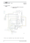
1
INSTRUMENT MANUAL
PerkinElmer 2030
Multilabel Reader
2030-9020-01
March 2008
PerkinElmer 2030
Multilabel reader
Valid for instruments with software version 4.0
PerkinElmer Life and Analytical Sciences, Wallac Oy, P.O. Box 10, FIN-20101 Turku, Finland.
Tel: 358-2-2678111. Fax: 358-2-2678 357. Website: www.perkinelmer.com
Warning
This equipment must be installed and
used in accordance with the
manufacturer's recommendations.
Installation and service must be
performed by personnel properly
trained and authorized by PerkinElmer
Life and Analytical Sciences.
Failure to follow these instructions may
invalidate your warranty and/or impair
the safe functioning of your equipment.
Contents
Contents
PerkinElmer 2030 multilabel reader .......................................................................... 7
Introduction .................................................................................................................................. 7
Models and Options ..................................................................................................................... 8
Single plate models ................................................................................................................... 9
Stacker models .......................................................................................................................... 9
Barcode reader option ............................................................................................................. 10
Dispenser option ..................................................................................................................... 10
Features of all models except PerkinElmer 2030-0050 ............................................................. 12
Fluorometry (top counting)..................................................................................................... 12
Fluorometry (bottom counting)............................................................................................... 16
Photometry.............................................................................................................................. 17
UV absorbance........................................................................................................................ 19
UV absorbance (photometry model)....................................................................................... 20
Time-resolved fluorometry ..................................................................................................... 21
Homogeneous time-resolved fluorometry, LANCE™ ............................................................ 22
Luminometry........................................................................................................................... 23
Luminometry (luminometry model) ....................................................................................... 24
Shaking of plates..................................................................................................................... 25
Kinetic measurements............................................................................................................. 25
Scanned measurements ........................................................................................................... 25
Temperature control................................................................................................................ 25
Dual filter measurements ........................................................................................................ 25
PerkinElmer 2030-0050 features................................................................................................ 26
Fluorescence polarization ....................................................................................................... 26
Fluorometry (top counting)..................................................................................................... 28
Fluorometry (bottom counting)............................................................................................... 29
Photometry.............................................................................................................................. 30
UV absorbance........................................................................................................................ 31
Time-resolved fluorometry ..................................................................................................... 32
Luminometry........................................................................................................................... 33
Appendix: Calculation method for LANCE TR-FRET normalization ...................................... 34
Introduction............................................................................................................................. 34
Configuration wells................................................................................................................. 34
Normalization measurements.................................................................................................. 35
Sample measurements............................................................................................................. 35
Example: ................................................................................................................................. 36
1
Contents
Information about user instructions ....................................................................... 39
Installation instructions .............................................................................................................. 39
User manual................................................................................................................................ 39
On-line help................................................................................................................................ 39
Routine maintenance .................................................................................................................. 39
Warnings .................................................................................................................................... 40
Routine Maintenance ............................................................................................... 43
Cleaning the instrument ............................................................................................................. 43
Instruments having TR-fluorometry mode................................................................................. 43
Dispenser maintenance............................................................................................................... 43
Needle maintenance ................................................................................................................... 44
Compacting the database............................................................................................................ 44
Changing the CW-Lamp ............................................................................................................ 45
Handling the optical filters......................................................................................................... 45
Specifications ........................................................................................................... 49
Power requirements.................................................................................................................... 49
Safety standards ......................................................................................................................... 49
Environmental conditions .......................................................................................................... 49
Light sources .............................................................................................................................. 49
Detection units ........................................................................................................................... 50
Plates .......................................................................................................................................... 50
Plate shaking .............................................................................................................................. 50
Scanning ..................................................................................................................................... 50
Repeats ....................................................................................................................................... 50
Measurement time ...................................................................................................................... 50
Performance ............................................................................................................................... 51
Physical dimensions ................................................................................................................... 51
Software ..................................................................................................................................... 51
Input/Output connections ........................................................................................................... 52
Options ....................................................................................................................................... 52
Stackers ................................................................................................................................... 52
Barcode reader (1420-221) ..................................................................................................... 52
Temperature control................................................................................................................ 52
TR-fluorometry (1420-110) .................................................................................................... 52
Expanded wavelength range to IR (1420-113) ....................................................................... 52
Dispenser options:................................................................................................................... 52
Enhanced security mode ......................................................................................................... 53
Counting modes.......................................................................................................................... 53
2
Contents
Instrument Installation ............................................................................................. 61
Environment ............................................................................................................................... 61
Electric power ............................................................................................................................ 61
Unpacking .................................................................................................................................. 62
Removing the Transport Protection Piece.................................................................................. 63
Check the mains voltage setting................................................................................................. 63
Software Installation ................................................................................................ 65
Minimum System Requirements................................................................................................ 65
Printer Installation...................................................................................................................... 65
Instrument Interface Card Driver Installation ............................................................................ 65
Installation of the DriverX device ROG .................................................................................... 66
ARCNET card device check................................................................................................... 68
Connect the instrument to the PC ........................................................................................... 72
Installation of the USB22 adapter .............................................................................................. 73
Connect the instrument to the PC ........................................................................................... 79
PerkinElmer 2030 Software Installation .................................................................................... 80
Setup........................................................................................................................................... 80
Liquid dispenser installation................................................................................... 90
1. Unpacking .............................................................................................................................. 90
2. Setting the robotic arm ........................................................................................................... 91
3. Electrical connections setup................................................................................................... 93
4. Installation of the pump unit .................................................................................................. 94
5. Dispenser calibration.............................................................................................................. 97
Equipment needed:..................................................................................................................... 97
Horizontal angle of the dispenser arm .................................................................................... 97
Measurement position of the dispenser arm ........................................................................... 97
Dispenser test .......................................................................................................................... 98
Final installation......................................................................................................................... 99
PerkinElmer 2030 Performance Test .................................................................... 100
Equipment needed:................................................................................................................... 100
Test procedure .......................................................................................................................... 100
Saving the EEPROM parameters to the hard disk ................................................................... 102
First time start up ................................................................................................... 103
Index ........................................................................................................................ 107
3
Contents
Trademarks
DELFIA is a registered trademark and Wallac and LANCE are trademarks of PerkinElmer,
Inc.
Windows is a registered trademark of Microsoft Corporation in the U.S. and other countries.
Pentium is a registered trademark of Intel Corporation
4
1. Functional description
Introduction
Models and options
Features of all models except PerkinElmer 2030-0050
Features of PerkinElmer 2030-0050
5
Functional description
PerkinElmer 2030 multilabel reader
Introduction
PerkinElmer 2030 multilabel reader is a complete platform for quantitative detection of lightemitting, or light absorbing markers. Depending on the model of the instrument you have, it is
suitable for flash or glow luminometry, fluorometry, high-sensitivity time-resolved
fluorometry (DELFIA®), UV absorbance, photometry, homogeneous time-resolved
fluorescence assays (LANCE™ option) and fluorescence polarization. It is a compact bench
top unit with features such as stacker, dispensers, shaker, temperature control, top or bottom
counting and scanning. The software is a 32-bit application running under Windows XP on a
PC connected to the instrument. Plates with up to 1536 wells can be counted, as well as Petri
dishes, slides filters and Terasaki plates. Plates can be loaded manually or with stackers for
automatic operation. Output can be to a file on the PC and/or to a laser printer.
PerkinElmer 2030 has an optional Enhanced Security mode intended for facilities that have to
comply with 21 CFR Part 11 regulation from the Food and Drug Administration (FDA) of the
USA. During installation you can select if you want to use the Enhanced Security mode. This
mode is described in the User manual.
7
Functional description
Models and Options
2030-0010 dedicated luminometry model – for luminometry only.
2030-0020 fluorescence and luminescence model – for fluorometry and luminometry.
2030-0030 photometry model – for fluorometry, luminometry and photometry (including UV
absorbance)
2030-0040 time-resolved fluorometry model – for fluorometry, luminometry, photometry,
(including UV absorbance) and time-resolved fluorometry.
2030-0050 all five leading technologies model - for fluorometry, luminometry, photometry
(including UV absorbance), TR-fluorometry and fluorescence polarization.
All models include temperature control and shaker operation.
8
Functional description
The following options are available for all models:
1420-221 Barcode reader
1420-2550 …. 1420-2580 One dispenser … 4 dispensers
2030-3010 Enhanced security mode software option
2030-1010 Stacker option
1420-113 Red sensitive PMT option is available for all models except 2030-0010
1420-110 The time-resolved fluorometry option can be fitted in the field to 2030-0020 and
2030-0030
1420-3050 WorkOut 2.5 Data Analysis software is included in models 2030-0030, 2030-0040
and 2030-0050 as standard and is available as an option for other models
Single plate models
In the models without stackers, a single microplate is loaded into the reader.
Stacker models
9
Functional description
In the stacker operation, plates are loaded into the input stacker with the first plate to be
measured at the bottom. The empty output stacker is fitted first into the multilabel reader; it
occupies the left hand position. Then the input stacker with plates is fitted in the right hand
position. During operation the plates are moved one by one from the input stacker to the
measurement position. After each plate has been measured, it is moved to the output stacker.
When measurement is complete the output stacker can be removed. A quick release
mechanism allows the plates to be emptied easily from the stacker.
Note: the stacker model can also be used as a single plate model if required.
Barcode reader option
An optional barcode reader can be included. This allows loading of barcode labelled plates,
which are identified by the barcode reader. This identification can be by plate number or
protocol number. In the former case, the protocol to be used for the measurement must be
specified. In the latter, the barcode identifies the protocol to be used for that plate. This system
is especially useful for the stacker models.
Dispenser option
The optional dispenser allows measurements to be made that require e.g. the addition of
reagent to start the process as in the case of flash luminescence or start and stop an enzyme
reaction. It can also be used for dispensing Enhancement Solution for a DELFIA time-resolved
10
Functional description
fluorometry measurement. It can be used with any of the technologies supported by
PerkinElmer 2030.
The dispenser can have up to four pumps fitted. This allows separate pumps to be dedicated for
specific purposes. All the needles are directed to the same well allowing dispensing of more
than one reagent to the same well. The number of pumps fitted and the total volume of each
pump are set during installation. This information then appears when dispenser maintenance is
selected. The default setting for the dispensed volume can be between 5 to 350 microliters.
The optional dispenser is a separate unit from PerkinElmer 2030 itself making for convenient
maintenance and flexibility in syringe selection.
11
Functional description
Features of all models except PerkinElmer 2030-0050
Note: PerkinElmer 2030-0050 features are described separately at the end of this chapter.
Fluorometry (top counting)
For PerkinElmer 2030-0020, -0030, -0040
12
Functional description
Inside PerkinElmer 2030 there is a tungsten-halogen continuous wave lamp (75 w, spectral
range 320 - 1000 nm) This is used as the light source for fluorometry and photometry
measurements. The actual wavelength used is selected by means of a wheel containing up to 8
filters. The filter to be used can be selected by means of the software. The spectral range of the
CW-Lamp is 320 - 1000 nm. Two positions of the standard 8-position filter wheel (filter wheel
A) are used for filters of 355 and 485 nm, which are specially designed for fluorescence
excitation. All standard filters are high quality interference filters with a diameter of 15 mm.
There are three empty filter positions into which customized filters can be inserted.
There are also two optional filter wheels: filter wheel B and filter wheel B2. Filter wheel B(left
side figure) has four positions for the most common size of commercial filters i.e. "round one
inch". Filter wheel B2 (right-hand figure) has 8 positions for filters with a diameter of 15 mm.
Both wheels are supplied empty but with locking rings.
13
Functional description
The system recognizes automatically if the type of wheel is A or B. However, if a B2 wheel is
used instead of the default type B you need to inform the system through the workstation
software. This is done by selecting “Use CW-lamp filter wheel B with 8 slots” in
Tools/Options/General:
Light of the selected wavelength having passed through the light guide is collimated through
the sample. You have the choice of using either stabilized energy mode or constant voltage
mode for ensuring that the results are calculated for constant illumination.
In stabilized energy mode a photodiode monitors the light used to illuminate the sample and
sends a signal to the CW-lamp to adjust the voltage as required to maintain constant
illumination.
In constant voltage mode, the CW-lamp voltage is not adjusted unlike in the stabilized energy
mode. A photodiode monitors the light used to illuminate the sample. The change in the signal
from this photodiode is used in the software to correct for changes in lamp intensity so as to
ensure that the results are calculated for the same illumination. In constant voltage mode it is
recommended that the lamp is run at full power. Constant voltage mode is recommended when
counting kinetic dual excitation fluorescence labels.
14
Functional description
In both modes, the energy range is user adjustable to help find the optimum linear range for
samples being measured and thus keep the output signal within the linear range of the
instrument.
In top counting the sample is illuminated from above and then the fluorescence shines up from
the sample and passes through a mirror slide, a lens system and an 8-position emission filter
slide to a low noise photomultiplier (spectral range 400 - 700 nm) equipped with fast single
photon counting electronics. There is also a combined shutter and aperture slide.
In the standard emission filter slide (A) there are two positions for emission filters of
conventional fluorescence at wavelengths of 460 and 535 nm.
Emission filter slide A can be replaced with another one which has no predefined filters, so
you can choose which filters you want to load. There are eight positions, the same as in filter
type A. The size is “round one inch”.
The excitation/emission pairs with wavelengths 355/460 and 485/535 are used for e.g.
umbelliferone and fluorescein, respectively.
Note: when the properties of a label are defined, then the filters to be used for measurements
with that label are specified. When a protocol is selected for a measurement, the appropriate
filters are moved into position automatically.
15
Functional description
Fluorometry (bottom counting)
For PerkinElmer 2030-0020, -0030, -0040
16
Functional description
In the case of bottom counting of prompt fluorescence samples, excitation light is directed
through a light guide underneath the plate. Emission light from the bottom of the sample goes
back along the same light guide to the optical block where the emission filter is and from there
to the PMT. Bottom counting allows measurements to be made for samples in which cells are
at the bottom of the wells or there are lids on wells.
Switching between top and bottom counting is done by software and both methods can be used
for the same plate.
Photometry
For PerkinElmer 2030-0020, -0030, -0040
17
Functional description
For absorbance measurements the same excitation system is used as for prompt fluorescence.
The wavelength of the light can be in the range 320 -1000 nm.
There are three positions in filter wheel A that are fitted with filters for the most common
absorption wavelengths i.e. 405, 450 and 490 nm.
In absorption measurements, light passes through the well to a photodiode beneath the sample
plate.
The intensity of the filtered and stabilised beam is first measured without any sample and then
the samples in one plate are measured. The absorbance value is then calculated from the
equation:
A = - log (I /I0 ),
where I0 is the light intensity measured without any sample ( a reference beam) and I is the
intensity after an absorbing or reflecting medium. Because the optical surfaces of the empty
well reflect backward about 8 % of optical energy, the measured absorbance values are always
about 0.04 A for a empty clear plate.
18
Functional description
UV absorbance
For PerkinElmer 2030-0040 and -0050
For UV absorbance measurements the same excitation system is used as for time-resolved
fluorescence. The wavelength of the light can be in the range 230 -320 nm.
There are two fixed positions in the flash excitation filter slide that are fitted with filters for the
UV absorption wavelengths i.e. 260 and 280 nm.
The measurement is as for normal photometry.
19
Functional description
UV absorbance (photometry model)
For PerkinElmer 2030-0030
The operation is as for normal PerkinElmer 2030 UV absorbance.
20
Functional description
Time-resolved fluorometry
For PerkinElmer 2030-0040
21
Functional description
This configuration is used for both types of time-resolved fluorescence measurements i.e.
DELFIA®, involving dissociation and enhancement, and LANCE homogeneous assays. For
enhanced performance with LANCE it is possible to install an optional red-sensitive detection
unit (PMT).
In time-resolved fluorometry, excitation light is produced by a UV xenon flash lamp (spectral
range 230 - 400 nm). The light passes through an excitation filter fitted into a slide. This slide
is not accessible to the user, unlike the CW-Lamp wheel and emission filter slide where filters
or the whole wheel or slide can be changed.
A lens and mirror system is used to direct the light through the sample well. Emission light
from the sample then passes through a lens and filter system to the photomultiplier just as in
the fluorescence case.
Both excitation and emission light are directed from the top of the well. If the adjustable beam
size option is installed then there is an additional flash excitation lens slide.
Two positions of the standard 8-position emission filter slide (A) are used for emission filters
suitable for labels of rare-earth chelates, i.e. Europium (615) and Samarium (642). Both these
filters are high-quality interference filters with quite narrow (6 - 8 nm) bandwidths and
exceptionally high peak transmissions (> 70%).
Note: these filters are only present if the time-resolved fluorometry option is included in the
instrument.
Homogeneous time-resolved fluorometry, LANCE™
To make LANCE measurements a correction procedure is required. This is handled in the
software by means of a normalization wizard, as described in the user manual and help. A
more detailed description of how the correction is applied is given as an appendix to this
chapter
22
Functional description
Luminometry
For PerkinElmer 2030-0020, -0030, -0040
Measurement of glow, flash and dual-type luminescence is possible with PerkinElmer 2030. In
luminometry there is no external excitation but the light is produced in the sample and then
passes through a lens and an empty position in the emission filter slide to the photomultiplier.
Although one filter position in the standard slide (A) is empty and is intended for luminescence
measurements, any of the filters can be specified to be used with a luminescent sample.
23
Functional description
Flash-type luminescence makes use of the dispenser option to initiate reactions by dispensing
reagent directly into the wells of the plate. See the information on the dispenser option
described earlier.
Luminometry (luminometry model)
For PerkinElmer 2030-0010
Actual operation is as for normal PerkinElmer 2030 Luminometry.
24
Functional description
Shaking of plates
The plate conveyor also acts as a shaker. You can specify how long, how fast and with what
amplitude the plate is shaken. A further feature is that the mode of shaking can be linear,
orbital or double orbital (figure of eight). Shaking occurs when the conveyor has moved the
plate to the measuring position.
Kinetic measurements
For reactions taking time, repeat measurements are necessary. PerkinElmer 2030 allows these
kinetic measurements to be made. The number of repeats (up to 300) can be specified and the
time between repeats, up to 3600 s. These fast kinetic measurements can only be made if "well
mode" is selected. Slow kinetic measurements can also be made using plate repeats.
Scanned measurements
Measurements can be made at different points of a well for samples in which the light output is
not homogeneous, e.g. in cell culture wells. The number of spots to be measured can be
defined. Up to ten spots can be measured in both the horizontal and vertical directions
(maximum of 100 points altogether). The distance between spots can be set. The distribution of
the measurement spots can be square or rounded.
Temperature control
The temperature control option maintains plates at a temperature specified by the user. This
can be between room temperature + 2oC and 50oC. The measuring chamber itself is heated, so
no special plate holder is needed. The PMT tube environment is maintained at 25oC.
Dual filter measurements
A second filter and other parameters can be specified for dual label measurements. In this case
the system rapidly changes the filter and immediately makes the second measurement for the
same well with no adjustments needing to be made in between.
25
Functional description
PerkinElmer 2030-0050 features
This model allows fluorescence polarization measurements in addition to the technologies
available in other models of PerkinElmer 2030. Fluorescence polarization requires a somewhat
different internal design so new pictures are shown here and the differences noted.
Fluorescence polarization
For PerkinElmer 2030-0050
26
Functional description
Light is produced by the same tungsten-halogen continuous wavelength lamp used for normal
fluorometry and photometry. In fluorescence polarization, the excitation energy control is only
by means of the constant voltage mode. The lamp is run at full power, with no voltage
adjustment.
Light from the CW-lamp is directed via a light-guide through a polarization excitation filter
slide. This has two positions with small and normal apertures. You can select which is of these
is to be used. The filter polarizes the light in the S-plane.
The polarized light is then directed by means of a mirror block onto the sample.
The polarized emission light passes back through the mirror block and through a polarization
emission filter. There are two of these in a slide. One filter is polarized in the S-plane and the
other at a right angle in the P-plane. Finally the light passes through an emission filter and then
to the PMT. One measurement is made with the S emission filter slide and the other with the P
emission filter slide. The final result is calculated by combining these measurements in the
formula:
Polarization (mP) = 1000 *
(S − G * P)
( S + G * P)
Where S and P are the measured results with the S and P emission filters respectively. G is a
factor to correct for the effect of emission filter transmission variation and sample viscosity.
See the PerkinElmer application note on Fluorescence polarization assays for more details.
27
Functional description
Fluorometry (top counting)
For PerkinElmer 2030-0050
This functions the same as in normal PerkinElmer 2030.
28
Functional description
Fluorometry (bottom counting)
For PerkinElmer 2030-0050
This functions as in normal PerkinElmer 2030.
29
Functional description
Photometry
For PerkinElmer 2030-0050
This functions as in normal PerkinElmer 2030.
30
Functional description
UV absorbance
For PerkinElmer 2030-0050
This functions as in normal PerkinElmer 2030.
31
Functional description
Time-resolved fluorometry
For PerkinElmer 2030-0050
This functions as in normal PerkinElmer 2030. The same configuration is used for both
DELFIA and LANCE technologies.
32
Functional description
Luminometry
For PerkinElmer 2030-0050
This functions as in normal PerkinElmer 2030.
33
Functional description
Appendix: Calculation method for LANCE TR-FRET normalization
Introduction
Before LANCE homogenous time-resolved fluorometry measurements can be made, the
instrument must be normalized for the protocol to be used. This procedure corrects for the
following effects in LANCE measurements:
- background from the plate
- crosstalk of the donor signal into the acceptor window
- quenching.
The final result is normalized to the maximum donor intensity.
This procedure is handled by a normalization wizard. The measurements and calculations used
to obtain the final results are described in this appendix.
Note: if the normalization is only required for a particular plate then normalization samples can
be included on the plate and run at the same time as the assay samples instead of using the
wizard.
In LANCE TR-FRET assays the sample interference can be corrected from the time-resolved
acceptor signal (A) based on the fact that the energy transfer signal is a direct function of the
excited states of donors in the complex. This traditional ‘ratio measurement’ is improved by
subtracting both blank (Bl) and donor crosstalk (c x D where D is the donor signal) values
from the time-resolved integral of acceptor signal (A) before calculating the ratio. The
corrected values are defined as a blank-corrected normalized ratio (Rn). Use of the equation
requires a configuration plate (or wells) where background due to the plate blank and the
contribution of the donor to the signal in the acceptor window can be measured. Maximum
energy transfer samples are also measured on the plate to allow actual sample measurements to
be normalized to the maximum donor value and thus eliminate the effect of any quenching that
there might be in the sample.
Note that all measurements have to be done with identical instrumental parameters with the
exception of filters (for donor and acceptor). This means that the microplate, buffer, reagent
concentrations and volumes should be the same as those to be used in the actual sample
measurements.
Configuration wells
Dispense the configuration samples (preferably in duplicate)
1. Blank control. Colourless pure assay buffer (Bl)
34
Functional description
2. Crosstalk control. Donor-labelled reagent (e.g. Eu) in the buffer. This is used to calculate
the cross-talk factor, c, expressed as the fraction of donor signal in the acceptor measuring
window.
3. High reference. Wells containing all the reagents required to form maximal energy transfer
signal. The donor intensity, Dmax is used to calculate the normalized ratio giving numeric
values similar to the unquenched energy transfer intensity.
Normalization measurements
The configuration plate/wells can be run separately or as part of the assay. Each well is
measured with both donor (D) and acceptor (A) filters using identical time-windows. The
following values are needed for calculations:
Bl: - The measurement of the buffer wells (1) i.e. the plate background in the
acceptor window (e.g. at 665 nm)
c (=(Adonor-Bl)/Ddonor), this crosstalk factor is obtained from the crosstalk
control wells (2). The contribution of the blank-corrected donor signal in the
acceptor window (Adonor-Bl) e.g. with 665 nm filter using a time window from
50 to 150 μs is calculated. This is divided by the donor signal in the donor
window (Ddonor) e.g. with a 613 nm filter in the identical time-window (50 – 150
μs). A typical crosstalk for the PerkinElmer chelate W1024 is 0.0025 (0.25 %)
Dmax: The donor signal from high reference wells (3). This value is used for
normalization.
Sample measurements
All samples are measured in the same windows to obtain the uncorrected results (D and A).
These results are then corrected using the following equation to give the final result (Rn):
Rn = (A-Bl-c x D) x (Dmax / D)
Where:
A is the fluorescence intensity of the sample in the acceptor window
D is the fluorescence intensity of the sample in the donor window
Bl, c and Dmax are obtained from the configuration
(A-Bl-c x D) = ET the actual energy transfer from the donor to the acceptor.
35
Functional description
If there is quenching in the sample, it will affect both the A and D measurements. The ratio
(Dmax / D) normalizes the result to the maximum intensity value and eliminates the effect of
quenching in the sample.
This can be seen in the following numerical example.
Example:
The three (normally three with duplicates) first wells contain the configuration samples.
Calibrator
Blank
Eu-component
High standard
D (613 nm)
150
500 000
400 000
(Dmax)
A (665 nm)
100
1350
50 000
(Amax)
Calculations
Rn
c = 0.0025
ETmax = 48 900
ETmax/Dmax =
0.12225
(0)
(48 900)
The following table gives the corrected values calculated for two samples. The first has a 50 %
lowered complex formation and is thus a true positive. The second sample is quenched by 50
% and without further correction appears as a (false) positive. I.e. the apparent energy transfer
in each case is the same 24 450 cps. The normalization Dmax/D reveals the true situation
showing the first result to be a true positive and the second not.
Samples
D (613 nm)
1. (50 %
inhibition)
2. (50 %
quenched)
450 000
A (665 nm)
25 675
200 000
25 050
Calculations
ET=24 450
ET/D = 0.0543
ET = 24 450
ET/D = 0.12225
Rn
21 733
48 900
Note: When using the blank corrected and normalized result as here, the linearity of assay
response is slightly over expressed. For example the sample inhibiting the complex formation
by 50 % (sample 1) gives a value which is only 44 % from the high standard. This is due to the
fact that at the same time as the energy transfer is increased, the donor signal is decreased.
36
2. Information about user instructions
and warnings
37
Information about user instructions and warnings
Information about user instructions
There are several forms of user instructions:
Installation instructions
These are part of the instrument manual and are not normally needed by the regular user but
only by the engineer who installs the PerkinElmer 2030 system. However you might need them
if you have to reinstall the system in another location at a future time.
User manual
This is a separate manual from this instrument manual. It gives information necessary for
operation of PerkinElmer 2030.
On-line help
This is supplied with the PerkinElmer 2030 software and can be accessed by clicking Help in
any PerkinElmer 2030 window. This help gives detailed information about all features of the
operation which concern the normal user (service information is not provided).
Routine maintenance
This is maintenance intended to be performed by the user and is described in a separate chapter
of this instrument manual. Any other maintenance than what is described there should be
performed by a qualified service person.
39
Information about user instructions and warnings
Warnings
The following warnings are found in the User manual
Note: Errors in protocol selection or plate layout definition will lead to incorrect results.
See page 29 Starting Operation with Start Wizard
CAUTION: do not put your fingers into the sample loading area
See pages 35 and 37 Stacker operation
Note: make sure you do not operate this mechanism when the stacker is loaded in
PerkinElmer 2030 because you may jam the conveyor.
See page 36 Stacker operation
Note: changes to protocols should only be made by authorized persons.
See page 47 Protocol editor
Note: These operations can affect the whole system and should only be undertaken by a
person qualified to do them.
See page 73 Tools menu.
In the Instrument manual on pages 92 and 95 users are reminded to make sure they save the
Admin username and Password that are used in the case of Enhanced Security mode
installations.
40
3. Routine maintenance
Cleaning the instrument
Dispenser maintenance
Compacting the database
Changing the CW-Lamp
41
Routine maintenance
Routine Maintenance
Cleaning the instrument
The conveyor surface should be kept clean to avoid dust and dirt entering into the optics at the
measuring position. The conveyor surface should be cleaned at least once a week using a soft
cloth or tissue paper soaked in a mild detergent solution or alcohol.
Instruments having TR-fluorometry mode
In case of spillage of a sample containing any signal generation component, clean the area
where the spillage occurred in a similar way to that described above, except that you first use
Enhancement Solution to remove e.g. the europium, then a mild detergent or alcohol and
finally distilled water. Let the area dry before starting to use the instrument.
Dispenser maintenance
In the Tools menu there is an item called Dispenser Maintenance. There is also an icon with
the same function. Clicking this menu command or icon invokes the Dispenser Maintenance
Setup dialogue to perform common dispenser maintenance operations. This is enabled only
when working with a system that has the dispenser installed. The current state of the
instrument server is shown at the top of the dialogue.
The setup dialogue presents you with a graphical representation of the number of pumps (1 - 4)
available when performing an operation. You can select the pump(s) that are going to perform
the operation by checking boxes under the respective pump pictures. The operation to be
43
Routine maintenance
performed can be either Fill, Empty or Flush; you can select the operation you wish to perform.
This is then performed on all the selected pumps.
Fill is used for filling the syringe and tubing before operation begins.
Empty is used after operation ends to empty the contents of the syringe and tubing back into
the bottle.
Flush is used for cleaning the syringe and tubing after it has been emptied.
Note: before performing this operation, make sure the tubing from each dispenser has been put
into water, as described earlier. Take the tubing out from the water. Empty any water
remaining in the tubing by clicking Fill. This draws air into the tubing and expels any water
drops. Fit the end of the tubing into the reagent bottle. Click Fill to fill the tubing with reagent.
Needle maintenance
Every time the dispenser has been used, the tubing must be flushed properly. When this is
done, the needles are rinsed at the same time. However, it is good to regularly clean the outside
of the needles.
Avoid touching the needles with your fingers. To clean the needles use e.g. a stick with a tip of
soft material dipped in ethanol, or use a spray bottle filled with ethanol. Be very gentle when
touching the needles so that they are not bent out of shape. Rinse with water.
The position of the needles is very critical for high quality performance. If a needle is bent, call
the service engineer to get the needle replaced. Do not try to re-adjust the damaged needle
because the quality of dispensing could be affected. Both the needle and the tubing will be
replaced as a set.
It is good to check the flow of liquid dispensed (during flushing). If the flow is not normal it
might indicate that the needle is partly blocked. If this has happened due to dried reagents, use
water and e.g. ethanol to dissolve the plug. If that does not help, the needle needs to be
changed; contact Service.
Compacting the database
You should run the PerkinElmer 2030 Database Maintenance program on a regular basis
(weekly or monthly depending how much you run PerkinElmer 2030). This program will
compact your database and will in some situations increase the software performance
drastically. If you do not do this you will find that after a while your PerkinElmer 2030
software is not running as fast as it used to.
You can find this program by clicking the PerkinElmer 2030 icon in your Windows Start
menu. It is called PerkinElmer 2030 Database maintenance.
44
Routine maintenance
Changing the CW-Lamp
If the CW-Lamp needs replacing - lift the cover to get access to the lamp. Make sure the lamp
is switched off and give the lamp chance to cool before removing it and replacing it. Follow the
instructions on the inside of the cover. You will probably find it easier to use your left hand to
remove the lamp from the clips holding it.
When you have replaced the lamp, close the cover and switch power on.
Handling the optical filters
The optical excitation and emission filters should be handled with care and touching the filter
surface should be avoided. If a filter is added or removed from the excitation filter wheel or the
emission filter slide, it should be handled at the edges only. If cleaning is required, any dust or
loose particles should be first removed with dry pressurized air. If necessary, gently wipe the
surfaces using lint-free lab towels and anhydrous alcohol. Use fresh towels for every wipe.
In a typical excitation and emission filter there is an arrow on the edge of the filter indicating
the direction of light rays. In filters with a mounting ring the direction of light is usually
determined by the direction of the ring (see fig).
45
Routine maintenance
The direction of light
Edge in the rim
The direction of light in the excitation filter wheel and emission filter slide is illustrated in the
figures below.
Excitation filter
The direction of light
Excitation filter wheel
Emission filter
The direction of light
Emission filter slide
46
4. Specifications
47
Specifications
Specifications
Power requirements
PerkinElmer 2030
Power consumption: 400 VA
Mains voltage 110 -120 V/ 220 - 240 V, 50/60 Hz
Liquid Dispenser
Power consumption: 200 VA
Mains voltage 100 – 240 V, 50/60 Hz
Safety standards
The instrument is designed to meet the following safety standards:
1. EN61010-1 Safety requirements for electrical equipment for measurement, control and
laboratory use. Part 1: General requirements.
2. EMC-Directive - EN50082-1 (immunity) and EN50081-1, EN61000-3-2 (emission)
Environmental conditions
Temperature 15 - 35°C
Relative humidity 10 - 85 %.
Light sources
Continuous light source for fluorometric and photometric measurements:
1. Tungsten-halogen lamp, 75W, lifetime > 300h, Spectral range 320 - 1000 nm
2. Rotatable filter wheel A, provided with 8 filter positions (Ø 15 mm). Standard high quality
interference filters 405 nm, 450 nm, 490 nm, 355 nm (not for fluorescence polarization), 485
nm. Changeable rotatable filter wheel B, provided with 4 filter positions (Ø 25.4 mm).
Changeable rotatable filter wheel B2, provided with 8 filter positions (Ø 15 mm)
Optional flash light source for TR-fluorometric measurements:
1. UV xenon flash tube, L4642 or equivalent, spectral range 230 - 400 nm.
2. Filter slide, provided with 3 filter positions (Ø22.4mm). Filters 340, 260 and 280 nm.
49
Specifications
Detection units
Photometry: Photo diode, photometric range 320-1000 nm
Fluorometry, luminometry and optional TR-fluorometry:
1. Photomultiplier tube, R 1527, optional R4632
2. Emission filter slide A, provided with 8 filter positions (Ø25.4mm) with the following
filters:
535 nm and 460 nm
Changeable emission filter slide B, provided with 8 filter positions (Ø25.4mm)
Optional filters: 615 nm, 642 nm
Plates
1 to 1536-well plates are compatible with the instrument.
Note: for luminometry and bottom reading, well densities above 384 are not recommended.
The user can define non-standard plate configurations. The maximum outer dimensions are
86.0 x 128.2 x 25 mm. For Terasaki plates and petri dishes, optional cassettes are available.
Minimum plate height is 4.0 mm.
Both opaque and clear plates are suitable (for photometric measurement a clear bottom is
required).
Plate shaking
Three plate shaking modes are available: linear, orbital and double orbital. Three speed levels
can be selected and the amplitude of the movement is adjustable.
Scanning
Scanning of wells (several measuring points within a well) are available for all technologies.
Repeats
Repeated measurements or operations can be defined by plate, strips or well.
Measurement time
Detection time per well is software selectable between 0.1 - 600 seconds.
50
Specifications
Performance
Technology
Fluorometry
Fluorescence
polarization
TRfluorometry
Photometry
UVabsorbance
Luminometry
Feature
Performance
Fluorescein
< 2 fmol / well
detection limit
Precision @ 1 < 5 mP
nM fluorescein
Europium
< 6 amol / well
detection limit
Eu-linearity
5 decades
Measurement
0- 4 A
range @ 405
nm
Accuracy @
< 2 % or
405 nm
+/- 0.01 A
Precision @
< 0.5 % or
405 nm
+/- 0.01 A
Measurement
0- 4 A
range @ 280
nm
Accuracy @
< 2 % or
280 nm
+/- 0.01 A
Precision @
< 0.5 % or
280 nm
+/- 0.01 A
Lower limit of < total flux from sample
detection
of 105 photons/s
Valid for
All models except 20300010
2030-0050
2030-0040, -0050
All models except 20300010, -0020
2030-0030, -0040, -0050
All models
Physical dimensions
Weight
Height
Width
Depth
46 kg (without stackers)
52 kg (stacker model)
354 mm (510 mm stacker model)
493 mm
595 mm
Software
The instrument program is run under Windows XP on a Pentium computer, minimum 128 MB
memory, equipped with a CD-ROM, XGA display minimum resolution 1024 x 768 pixels, 64K
colours and a Wallac instrument interface card.
51
Specifications
Input/Output connections
PC: coaxial ARCNET connector (93 ohm). The PC must be provided with a
Wallac Instrument Interface.
Dispenser connection
Printers:
Connected to PC, parallel port or USB
Options
Stackers
A semi-automated plate loading option, including an input stacker, and an output stacker. 20
plates/load (1420-216) or 40 plates/load (1420-217 Input stacker, 1420-218 Output stacker).
The stacker is designed to take plates that fulfil the following requirements:
Length:
Width:
Height:
Ledge height:
127.2 – 128.2 mm
84.5 – 86.0 mm
14.0 – 25.0 mm
1.5 – 6.5 mm
Barcode reader (1420-221)
Barcodes that can be read: EAN, UPC, 2 of 5 interleaved, CODEBAR, CODE39, CODE128
Temperature control
The temperature of the measuring chamber can be regulated from “ambient +2 oC” to 50 oC.
The PMT is isolated and kept at 25 oC.
TR-fluorometry (1420-110)
The TR-fluorometry optics are based on a xenon flash lamp. The counting delay can be set
from 0 to 65515 s. Included in this option are flash absorbance and dual window TRfluorescence counting.
Expanded wavelength range to IR (1420-113)
The wavelength range is expanded up to 850 nm.
Dispenser options:
1-channel Dispenser (1420-2550)
2-channel Dispenser (1420-2560)
3-channel Dispenser (1420-2570)
4-channel Dispenser (1420-2580)
From 1 to 4 channels can be directed to a single well depending on the option used.
The default volume range is 5-350 µL in 1 µL increments.
52
Specifications
Accuracy typically
<5% for 5 µL
<0.5% for 50 µL
<0.05% for 350 µL.
Precision typically: <1.4% for 5 µL
<0.2% for 50 µL
<0.02% for 350 µL.
Speed: minimum and maximum speed are related to the volume.
Dead volume
<0.5 mL
Tubing
Inner diameter 0.7 mm
Outer diameter 2.0 mm
Material
PTFE
Enhanced security mode
The Enhanced Security mode is intended for facilities that have to comply with the 21 CFR
Part 11 regulation from the Food and Drug Administration (FDA) of the USA. If required, it
must be selected during installation.
Counting modes
Note: counting modes included depend on the model.
Fluorescence (320 – 700 nm,) (emission up to 850 nm optional)
Bottom fluorescence (320-700 nm) (up to 850 nm optional)
Time-resolved fluorometry (TRF)
LANCE
Fluorescence polarization
Dual window TRF
Glow luminescence
Flash luminescence
Dual luminescence
Photometry (320-1000 nm)
UV absorbance (230 - 320 nm)
Dual excitation fluorescence
Dual emission fluorescence
Scanning
Fast and slow kinetic measurements
53
5. WEEE instructions for PerkinElmer
products
55
WEEE Instructions for PerkinElmer Products
or
A label with a crossed-out wheeled bin symbol and a rectangular bar indicates
that the product is covered by the Waste Electrical and Electronic Equipment (WEEE)
Directive and is not to be disposed of as unsorted municipal waste. Any products
marked with this symbol must be collected separately, according to the regulatory
guidelines in your area.
The objectives of this program are to preserve, protect and improve the quality of
the environment, protect human health, and utilize natural resources prudently and
rationally. Specific treatment of WEEE is indispensable in order to avoid the dispersion
of pollutants into the recycled material or waste stream. Such treatment is the most
effective means of protecting the customer’s environment.
Requirements for waste collection, reuse, recycling, and recovery programs vary
by regulatory authority at your location. Contact your local responsible body (e.g.,
your laboratory manager) or authorized representative for information regarding
applicable disposal regulations. Contact PerkinElmer at the web site listed below for
information specific to PerkinElmer products.
Web address:
http://las.perkinelmer.com/OneSource/Environmental-directives.htm
Customer Care:
1-800-762-4000
(+1) 203-925-4602
(inside the USA)
(outside the USA)
0800 40 858
0800 90 66 42
(Brussels)
(Monza)
Products from other manufacturers may also form a part of your PerkinElmer
system. These other producers are directly responsible for the collection and
processing of their own waste products under the terms of the WEEE Directive. Please
contact these producers directly before discarding any of their products.
Consult the PerkinElmer web site (above) for producer names and web addresses.
57
58
6. Installation information
PerkinElmer 2030 Installation Instructions
Liquid Dispenser Installation
Liquid Dispenser Calibration
Performance Test
59
60
Instrument installation
Instrument Installation
Environment
Although normal clean laboratory conditions are usually quite satisfactory as an operational
environment it is useful to take the following points into consideration.
Ventilation in the room should be adequate for all conditions of use, the temperature should be
reasonably constant at about 220C, relative humidity should not be excessive, and direct
sunlight should not be able to reach the instrument.
Electric power
Three electrical outlets each with a protective earth should be available, with, if possible, a
separate power line for the instrument itself having an isolation switch and a fuse box. If
excessive fluctuations in the mains voltage are anticipated, a mains stabilizer may be
necessary.
61
Instrument installation
Unpacking
1. Cut the belts and remove the screws
2. Lift the lid off
3. Lift out the accessories and check them according to the packing list
4. Lift the instrument up and move it to its place of operation
5. For the stacker model, remove the transport protection piece (see fig. on next page)
6. Check for possible damage
62
Instrument installation
Removing the Transport Protection Piece
For preventing the stacker from moving and getting damaged during the transport, there is a
protection piece assembled. Remove this by opening the screws and slide the piece out from
the stacker.
Check the mains voltage setting
The fuse holder of the mains voltage selector is covered by the following sticker.
Its purpose is to alert you to the fact that the fuse holder is set for 220-240 V.
If this setting is not suitable because of the voltage of the mains the instrument is to
be connected to, you must change the voltage selector. To do this, pull out the
voltage selector, change the fuses, turn it round and replace it. See the pictures on
the next page. Make sure you use the correct fuses.
• connect the mains cable
• connect the ARCNET cable to port A
63
Instrument installation
• check that the terminator is properly fitted into port B
Mains 220 - 240V
TO WALLAC INTERFACE
T - CONNECTOR TERMINATOR
93 R BNC
75 R BNC - T
1186 0014
1186 0015
ARCNET
FUSES
T 3A
Mains
110-120V
FUSES
T 2A
MAINS
110 - 120V
FUSES
T 1.6A
220-240V
FUSES
T 1AMains
MAINS
220 - 240V
150VA
150 VA50/60Hz
50/60 Hz
ARCNET CABLE
RG 62 / 93 ohm
4,5 m
1085 9032
A
POWER
I
0
B
TERMINATOR
93 R BNC
1186 0015
110- 120V
USE ONLY WITH 250V
FUSES / EMPLOYER
UNIQUEMENT AVEC
DES FUSIBLES DE 250V
220- 240V
220 - 240V
Mains 110 - 120V
TO WALLAC INTERFACE
T - CONNECTOR
75 R BNC - T
1186 0014
TERMINATOR
93 R BNC
1186 0015
ARCNET
FUSES
T 3A
Mains
110-120V
FUSES
T 2A
MAINS
110 - 120V
FUSES
T 1.6A
220-240V
FUSES
T 1AMains
MAINS
220 - 240V
150VA
50/60Hz
150 VA 50/60 Hz
ARCNET CABLE
RG 62 / 93 ohm
4,5 m
1085 9032
A
POWER
I
0
B
TERMINATOR
93 R BNC
1186 0015
220- 240V
USE ON LY WITH 250V
FUSES / EMPL OYER
UNIQUEMENT AVEC
DES FUSIBL ES DE 250V
110- 120V
110 - 120V
64
Software installation
Software Installation
Minimum System Requirements
• Windows XP
• Intel Pentium Processor
• 128 MB RAM (or more)
• 30 MB free hard disk space (or more)
• CD-ROM Drive
• XGA Drive (minimum setting is 1024 by 768 pixels)
• Wallac Instrument Interface Board
Printer Installation
Install the printer according to the instructions accompanying the printer.
Instrument Interface Card Driver Installation
The following ARCNET adapters can be used:
6000 0569
PerkinElmer ARCNET adapter model Wallac ROG
1224-2030
PerkinElmer ARCNET adapter model USB22-CXB
65
Software installation
Installation of the DriverX device ROG
Note: If the desktop PC is ordered from PerkinElmer with the instrument, this instrument
interface card and the software are already installed and the instrument can be directly
connected to the PC.
Installation of the following ARCNET card is described here:
6000 0569
PerkinElmer ARCNET adapter model Wallac ROG for personal computers
Note: see the separate section for how to install the USB adapter if you are using it instead.
Configure the Wallac instrument interface card in the following way:
O N = C L O S E D = 1
O F F = O P E N = 0
1 2 3 4
Install the instrument interface card to the PC. Please refer to the PC manufacturer’s
instructions for adding expansion cards.
Start the PC. Once up and running, you will get a message that the computer has found a new
piece of hardware.
Note: “Found New Hardware Wizard” may not start right after the operating system is up
and running. Please wait for a while.
When you start up the computer the ARCNET card installed the following instructions will
guide you through the installation procedure.
66
Software installation
First insert the PerkinElmer 2030 CD then select “Install from a list or specific location
(Advanced)”. Click Next.
The option “Search for the best driver in these locations” and check box “Search removable
media” should be selected. Click Next. The driver will be found and installed.
67
Software installation
Click Finish to close the wizard.
ARCNET card device check
Click Start.
Select Control Panel.
From the control panel select Switch to Classic View.
Then select the System icon.
68
Software installation
Select the Hardware tab.
Click the Device manager button.
Check that the correct driver is installed.
Double-click on the driver.
69
Software installation
Check that you get the message that the device is working properly.
Click the Driver tab.
Click the Driver details button.
70
Software installation
Check that the driver shown in the picture is the one in use on your system. Click OK.
Click the Resources tab.
71
Software installation
Check that “No conflicts” appears. The information should be as shown in the appropriate
figure.
Close the device information display.
Close the device manager.
Close the control panel.
Connect the instrument to the PC
Connect the coaxial cable between the instrument and the Wallac instrument interface card
installed in the computer. Switch on the instrument.
72
Software installation
Installation of the USB22 adapter
Connect the USB22 adapter to the USB port you will use for the instrument connection. The
‘Found New Hardware Wizard’ will open (other ports need separate installations ).
Select ‘No’ for Windows Update connection and click ‘Next>’.
The installation requires ‘Found New Hardware Wizard’ to be run twice. The first time a
generic USB Device is found.
73
Software installation
Insert the 2030 Software CD into the drive, select ‘Install the software automatically’ and click
‘Next>’.
While installing the software the following dialog will appear.
Click ‘Continue Anyway’.
Click ‘Finish’ and wait until ‘Found New Hardware Wizard’ opens again.
74
Software installation
Select ‘No’ for Windows Update connection and click ‘Next>’.
The USB ARCNET adapter is found and software for it will be installed. Select ‘Install the
software automatically’ and click ‘Next>’.
75
Software installation
Select usb22.inf and click ‘Next>’.
Click ‘Continue Anyway’.
76
Software installation
Browse the Support\Driver\USB22 folder for the USB22DRV.SYS file.
Click ‘OK’ to copy the file.
77
Software installation
Complete the wizard by clicking ‘Finish’. The installation of the USB22 ARCNET adapter is
now ready.
To check that the driver is working properly, right-click ‘My Computer’ and select
‘Properties’.
On the ‘Hardware’ tab of ‘System Properties’ click ‘Device Manager’.
78
Software installation
The USB ARCNET adapter should be visible under the ‘Universal Serial Bus Controllers’.
Right-click to see the properties of the adapter. Check the device status.
Connect the instrument to the PC
Connect the coaxial cable between the instrument and the Wallac instrument interface card
installed in the PC. Switch on the instrument and the PC.
79
Software installation
PerkinElmer 2030 Software Installation
When installing the PerkinElmer 2030 Software, you MUST belong to the local Administrators
group. Otherwise the security system of Windows prevents the correct installation of the
PerkinElmer 2030 Software.
Any end user of the PerkinElmer 2030 Software must belong either to the 'Administrators' or
'Power Users' group.
Note: Do not use more than one account at the same time (without logouts) in Windows XP.
Note: In Enhanced security mode the Administrator should prevent power users being able to
change the system clock.
Setup
Exit all Windows programs and insert the PerkinElmer 2030 Software CD-ROM into the PC;
the setup will start automatically. If not click the setup on the CD:
The following dialogues will appear when the setup is started. Read them carefully and follow
the instructions (for first time installation the default values should normally be used).
80
Software installation
Click Next to proceed:
Read the terms of the licence agreement, then click Yes.
81
Software installation
This screenshot shows an example user name and company name. Enter your own information,
then click Next.
If the proposed destination folder is OK, click Next. Otherwise click Browse and select a new
destination folder. When you have done this, then click Next.
82
Software installation
Select the features you want to install, then click Next. The “Result and protocol database”
option is selected by default and greyed.
If you have not selected Enhanced security mode, the next dialogue to appear is the Select
mode dialogue (see the screen shot at the bottom of the next page).
If you have selected Enhanced security then you must give the Enhanced security installation
code as shown in the following screenshot. You will find this number on a sticker with the
software CD.
83
Software installation
Note: Make sure you save the Enhanced Security installation code in case you need it in the
future.
When you have given the installation code, click Next.
Click Next if your PC is connected to the instrument. With no instrument, the workstation can
be run in demo mode and the software itself simulates the instrument. In that case select Demo
and click Next.
84
Software installation
If all settings are OK, click Next.
Wait until the setup is completed.
If you have selected Enhanced security mode, the following two dialogues will appear before
the flash update procedure begins. If you have not selected it, the software installation will
continue directly with the flash update.
Give the username and password for the Administrator in the Enhanced security mode. Click
Next.
85
Software installation
Click Close. In demo mode the installation will jump to the last screen of the installation
process (Installshield wizard complete). In normal mode when the instrument is connected, the
installation will continue with the flash update.
Note: If the software with Enhanced Security is uninstalled and then reinstalled, it will not ask
for a new Username and Password. It is therefore important that you keep the Admin.
Username and password.
Click Next (this part is for setting up the communication between the PC and PerkinElmer
2030).
86
Software installation
If all connections are OK and the instrument is switched on, click Next.
If the instrument is not connected you will get the following dialogue.
In this case the instrument was not switched on so the connection could not be established.
Check connections and power and click the Back button when everything is OK.
Click the Next button again.
If a connection can be established, the flash ROMs are updated (=”BIOS ROMs” of the
instrument) so that they correspond to the program version of the instrument.
87
Software installation
Warning! Do not interrupt this procedure by switching off the PC or the
instrument. Wait until the update is completed because an interrupt can cause
permanent damage on the microcontroller boards and the only way to recover
from this is to replace the boards!
.....and when the update is finished the following dialogue is shown:
Click Finish to end the flash update procedure.
88
Software installation
Click Finish to proceed. Remove the PerkinElmer 2030 Software CD from the drive.
Continue with dispenser installation, if required, then do the performance test.
89
Liquid dispenser installation
Liquid dispenser installation
1. Unpacking
Open the package and carry the instrument to its place of operation.
Unscrew the two thumbscrews and remove the side cover. Keep the screw aside as they will
be used to secure the dispenser after installation..
Remove thumbscrews
Remove the cover by unfastening the three side screws and the pressing on the two catches on
the front end of the instrument (see fig below).
90
Liquid dispenser installation
2. Setting the robotic arm
Open the lid of the dispenser unit. The robotic arm block is attached to the dispenser unit with
a metallic protection plate and the arm is locked with a cable tie during transportation.
Remove the robotic arm from the dispenser unit by removing the cable tie and protection
plate as indicated in the figure below.
Check that the robotic arm is perpendicular to the base by using a try square or an engineer’s
square as indicated in the next figure. Ensure that they are at a right angle (90º) to each other.
If they are not perpendicular, loosen (2x) and adjust (1x) the screws on the base (see the
figure below). Turning it clockwise will adjust the robotic arm downwards while turning it
anti-clockwise will adjust the robotic arm upwards.
91
Liquid dispenser installation
Once the robotic arm is perpendicular, secure it to PerkinElmer 2030 (see fig below) by
means of screws (3x). Adjust the height of the arm before tightening them (for detailed
instructions, please see below).
Attach and secure arm with
the three screws
To adjust the height of the robotic arm - locate the arm to a couple of millimeters away
from PerkinElmer 2030 and adjust the screws for the guide pins so that the height between
PerkinElmer 2030 and the arm is 1-1.5 mm. Push the arm completely into the instrument
and check that it moves freely without touching the measurement head on the way in.
Adjust height position of the arm
When the height is O.K, tighten the three screws.
92
Liquid dispenser installation
3. Electrical connections setup
Slide the dispenser unit over the arm
Connect the two connectors (Opto and Motor) for the robotic arm to the main instrument.
Note: Be careful to get the connections the right way round.
Connect the RS-cable and the power cable between PerkinElmer 2030 and the dispenser unit.
Connect the dispenser unit to the mains voltage and switch the power on for both PerkinElmer
2030 and the dispenser unit.
93
Liquid dispenser installation
Load the PerkinElmer 2030 Service Program, initialize and then select the dispenser unit:
Check first the existing options: System‚ Options‚ Show‚ and then SetOptions‚ add Dispenser
to the existing options. Calibrate the arm (see calibration instructions).
4. Installation of the pump unit
Open the lid cover and remove the tube and pump protection cover (see the figure below).
Remove the pump cover and screws (2x) before installing the pump unit.
94
Liquid dispenser installation
To install the pump unit, simply slide the pump unit into position (as indicated in the picture
below) before securing it to the dispenser unit with screws (2x).
Connect the tubes (2x) to the pump unit as indicated in the pictures.
95
Liquid dispenser installation
96
Dispenser calibration
5. Dispenser calibration
Equipment needed:
- 96-well solid clear plate
- 1086 3400 Adjustment tool for the dispenser arm
Horizontal angle of the dispenser arm
With the power switched off, open the top cover of the dispenser and check the arm by
moving it manually in and out. Check that the arm does not scratch the upper part of the
measurement head and that the space between the arm and the upper part of the measurement
head is 1 – 2 mm.
Note: If the arm is too low it will hit against the measurement plate during normal use and the
dispenser needle(s) might be damaged.
Adjust
1-2mm
Wallac 1420 Measurement Head
Adjusting
Directions
Loosen
Once the arm looks OK, manually switch the system on and go to the next step:
Measurement position of the dispenser arm
Check the position of the arm in the following way.
Load and initialize the service program and run the arm to the measurement position:
Insert the adjustment tool and click OK, then run the arm to the measurement position by
clicking:
97
Dispenser calibration
Now the arm goes to the measurement position. Check that the horizontal angle is OK. Click
GoToCurrent a couple of times and check. If everything is OK, with the adjustment tool
mirror check the position of the needle(s). Calibrate the needle(s) to the center sideways with
right or left buttons and the in & out position by adjusting with the adjustment screw (see fig
below).
Once the needles are in the center, click Save and GoToCurrent for a last check. Remove the
calibration tool and make the following test of the dispenser:
Dispenser test
Fill the pump(s) with water by clicking the prime button twice.
Use a 96-well solid clear plate for the test. Test each pump separately.
Dispense 50 μl/well into the first strip (speed 4).
If there is water outside the well or on the walls, calibrate the arm again.
If the water is dispensed into the wells normally, dispense twice to the whole plate,
100 μl/well (speed 4). Check the result.
98
Final installation
Final installation
After calibrating the arm, install the PerkinElmer 2030 cover and secure with the side screws
(3x). Slide the dispenser against the PerkinElmer 2030. Ensure the dispenser fits into the
grooves on the side.
Secure the dispenser with the thumb screws (2x) (see the figure below).
Tighten dispenser unit to
PerkinElmer 2030 with
screws (2x)
Adjust the height of the dispenser by turning the feet of the dispenser until all four feet rest
flat on the surface. Turning the screw clockwise to lift the dispenser and anti-clockwise to
lower it
99
Performance test
PerkinElmer 2030 Performance Test
Equipment needed:
1420-442
Testplate 1420-442
Test procedure
Load the service program and run the service program performance test. Print the results:
Check that the results are within the limits shown on the next page. Note that not all
instruments have all the options and the different models have different limits.
100
Performance test
PERKINELMER 2030 PERFORMANCE TEST RESULTS
Limits:
Normal
Red sensitive FP models
tube option
TIME-RESOLVED FLUOROMETER RESULTS
Dark counts
:
Instrument background
:
Sample counts
:
Sample flashes
:
< 150
<600
>30000
900 – 1250
<600
<3800
>30000
900 – 1250
<600
<3800
>30000
400-700
UV PHOTOMETER RESULTS
Filter
:
Sample absorbance
:
Sample flashes
:
280 nm
1.6 – 2.2 A
1000
280 nm
1.6 – 2.2 A
1000
280 nm
1.6 – 2.2 A
1000
TIME-RESOLVED FLUOROMETER (2MM BEAM) RESULTS
Label
: Europium
Dark counts
:
<450
Instrument background
:
<1800
Sample counts
:
>30000
Sample flashes
:
2500 – 4000
<1800
<1800
<5400
<5400
>30000
>30000
2500 – 4000 1000-2500
FLUOROMETER (TOP COUNTING) RESULTS
Label
: FITC
Dark counts
:
<350
Instrument background
:
<3500
Sample counts
:
>500000
<1500
<12000
>500000
<1500
<12000
>500000
FLUOROMETER (BOTTOM COUNTING) RESULTS
Label
: FITC
Dark counts
:
<350
Instrument background
:
<10000
Sample counts
:
>75000
<1500
<10000
>75000
<1500
<10000
>75000
PHOTOMETER RESULTS
Filter
: 405 nm
Sample absorbance
:
Test Plate Value +/-10% (all models)
LUMINOMETER RESULTS
Dark counts
:
Instrument background
:
Sample counts
:
<350
<350
>10000
FLUORESCENCE POLARIZATION RESULTS
Signal S
:
Signal P
:
Polarization
:
101
<1500
<1500
>10000
<1500
<1500
>10000
>100 000
NS
>400 mP
Performance test
Saving the EEPROM parameters to the hard disk
Save all EEPROM parameters on the hard disk. The parameters can be restored if the LCC-C
board(s) has to be replaced.
Click Yes
Click OK
102
First time start up
First time start up
The first time you start the software after installation, click your Windows Start button. Select
programs and from that menu PerkinElmer 2030. Select PerkinElmer 2030 Workstation as
shown in the picture.
The following dialogue will appear.
Click Yes. The workstation software will then start up normally. See the user manual for
operation information.
103
7. Index
105
106
Index
Index
Dispenser maintenance, 49
Needle, 50
Dispenser option, 10
Dispenser options, 60
Dual filter measurements, 27
2
21 CFR Part 11, 7, 61
A
E
Absorbance, 19, 21
ARCNET adapter installation, 74
USB installation, 81
Emission filter slide, 16
Enhanced security, 61
Enhanced security mode, 7, 9, 91
B
F
Barcode reader, 9, 60
Barcode reader option, 10
Barcodes, 60
Bottom counting, 18, 33
Fill, 50
Filter wheel, 14
Filters, 13
Cleaning, 51
Handling, 51
Mounting, 52
Fluorescence polarization, 28
Fluorometry
Bottom counting, 18, 33
Top counting, 12, 32
Flush, 50
C
Cleaning, 49
Configuration samples, 39
Connections, 60
Constant voltage mode, 32
Continuous wave lamp, 13
Counting modes, 61
CW-Lamp, 13
H
D
Help, 45
Homogeneous TRF, 24
Humidity, 57
Database maintenance, 50
DELFIA, 24, 37
Dimensions, 59
Dispenser, 9
Calibration, 105
Test, 106
Dispenser installation, 98
I
Installation, 69
Software, 73
Installation instructions, 45
107
Index
Instrument features, 7
Power requirements, 57
Pump unit, 102
K
R
Kinetic measurements, 27
Red sensitive PMT, 9
Repeats, 58
Routine maintenance, 45, 49
L
Lamp, 57
Changing the CW-Lamp, 51
CW, 13, 29
Flash, 24
Spectral range, 13
LANCE, 24, 37
LANCE calculation, 39
LANCE normalization, 24, 39
Luminescence
Dual, 25
Flash, 25
Glow, 25
Luminometry, 25, 38
S
Scanned measurements, 27
Scanning, 58
Shaker option, 8
Shaking, 58
Shaking of plates, 27
Software, 59
Specifications, 57
Stabilized energy mode, 32
Stacker operation, 10
Stackers, 9, 10
M
T
Mains voltage, 71
Maintenance, 49
Models and options, 8
Temperature, 57
Temperature control, 8, 27, 60
Time - measurement, 58
Time-resolved fluorometry, 24, 37
Top counting, 12, 32
TR-FRET, 39
N
Normalization measurements, 40
U
P
Unpacking, 70
USB adapter installation, 81
User instructions, 45
Performance, 59
Performance test, 108
Photometry, 19, 21, 34
Plate shaking, 58
Plates, 58
Polarization, 29
W
Warnings, 46
108