1
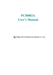
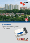
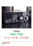
Model PCL - 726
Six Channel
D/A Output Card
PCL-726 SIX CHANNEL D/A OUTPUT CARD
USER'S MANUAL
Copyright Notice
This documentation and the software routines contained in the PCL726 software diskette are copyrighted, 1989, by Advantech Co., Ltd.
All rights are reserved. Advantech Co., Ltd. reserves the right to
make improvements to the products described in this manual at any
time without notice.
No part of this manual may be reproduced, copied, translated or
transmitted, in any form or by any means without the prior written
permission of Advantech Co., Ltd. Information provided in this
manual is intended to be accurate and reliable. However, Advantech
Co., Ltd. assumes no responsibility for its use; nor for any
infringements of rights of third parties which may result from its use.
Acknowledgement
PC-LabCard is a trademark of Advantech Co., Ltd. IBM and PC are
trademarks of International Business Machines Corporation. MSDOS is a trademark of Microsoft Corporation. BASIC is a
trademark of Dartmouth College. Intel is a trademark of Intel
Corporation .
Part No. 2003726000 Rev. Al
Printed in Taiwan May. 1994
Table of Contents
1. GENERAL INFORMATION . . . . . . . . . . . . . . . . . . . . . . . . . . . . . . .
1.1. Description . . . . . . . . . . . . . . . . . . . . . . . . . . . . . . . . . . . . . . .
1.2. Features . . . . . . . . . . . . . . . . . . . . . . . . . . . . . . . . . . . . . . . . . .
1.3. Specifications . . . . . . . . . . . . . . . . . . . . . . . . . . . . . . . . . . . . .
1.3.1. Analog Output . . . . . . . . . . . . . . . . . . . . . . . . . . . . . .
1.3.2. Digital Input . . . . . . . . . . . . . . . . . . . . . . . . . . . . . . .
1.3.3. Digital Output . . . . . . . . . . . . . . . . . . . . . . . . . . . . . .
1.3.4. General Specifications . . . . . . . . . . . . . . . . . . . . . . .
1
1
1
2
2
3
4
4
2. INSTALLATION . . . . . . . . . . . . . . . . . . . . . . . . . . . . . . . . . . . . . . . . 5
2.1. Initial Inspection . . . . . . . . . . . . . . . . . . . . . . . . . . . . . . . . . . . 5
2.2. Jumper Settings . . . . . . . . . . . . . . . . . . . . . . . . . . . . . . . . . . .
5
2.2.1. Base Address Selection . . . . . . . . . . . . . . . . . . . . . . . . 5
2.2.2. Wait State Selection . . . . . . . . . . . . . . . . . . . . . . . . . . 6
2.2.3. Reference and Mode Selection . . . . . . . . . . . . . . . . . . 7
2.3. Connector Pin Assignment . . . . . . . . . . . . . . . . . . . . . . . . . . . 8
2.4. Hardware Installation . . . . . . . . . . . . . . . . . . . . . . . . . . . . . . 10
2.5. Software Installation . . . . . . . . . . . . . . . . . . . . . . . . . . . . . . . 11
3. SIGNAL CONNECTION . . . . . . . . . . . . . . . . . . . . . . . . . . . . . . . . .
3.1. Introduction . . . . . . . . . . . . . . . . . . . . . . . . . . . . . . . . . . . . . .
3.2. Voltage Output Connection . . . . . . . . . . . . . . . . . . . . . . . . . .
3.3. 4 to 20mA Current Output Connection . . . . . . . . . . . . . . . . .
3.4. Programmable Attennuator Connection . . . . . . . . . . . . . . . .
3.5. Digital Signal Connection . . . . . . . . . . . . . . . . . . . . . . . . . . .
13
13
13
14
15
16
4. REGISTER STRUCTURE AND FORMAT . . . . . . . . . . . . . . . . .
4.1. Introduction . . . . . . . . . . . . . . . . . . . . . . . . . . . . . . . . . . . . . .
4.2. I/O Port Address Map . . . . . . . . . . . . . . . . . . . . . . . . . . . . . .
4.3. D/A Output Registers . . . . . . . . . . . . . . . . . . . . . . . . . . . . . . .
4.4. Digital I/O Registers . . . . . . . . . . . . . . . . . . . . . . . . . . . . . . .
17
17
17
18
18
5. APPLICATION . . . . . . . . . . . . . . . . . . . . . . . . . . . . . . . . . . . . . . . . .
5.1. D/A Applications . . . . . . . . . . . . . . . . . . . . . . . . . . . . . . . . . .
5.2. Digital Input and Output . . . . . . . . . . . . . . . . . . . . . . . . . . . .
20
20
21
APPENDIX A. BLOCK DIAGRAM . . . . . . . . . . . . . . . . . . . . . . . . . . . 22
APPENDIX B. CONNECTOR, SWITCH AND VR LOCATIONS . . 23
APPENDIX C. PC I/O PORT ADDRESS MAP . . . . . . . . . . . . . . . . . . 24
APPENDIX D. CALIBRATION . . . . . . . . . . . . . . . . . . . . . . . . . . . . . . 25
D.1. VR Assignment . . . . . . . . . . . . . . . . . . . . . . . . . . . . . . . . . . . . 25
D.2. D/A Calibration . . . . . . . . . . . . . . . . . . . . . . . . . . . . . . . . . . . . 25
1. GENERAL INFORMATION
1.1. Description
The PCL-726 provides six analog output channels on a single PC-BUS add-on
card. Each channel can be set individually to any of the following ranges: 0 to
5V, 0 to 10V, +/-5V, +/-10V and 4 to 20mA current output. Designed for
rugged environment, the PCL-726 is an ideal and economical solution for
industrial application requiring multiple analog voltage and/or current output
channels.
In addition to the analog output, PCL-726 also provides 16 channels of digital
output and 16 channels of input. The D/I and D/O ports are TTL compatible
and designed to be fully compatible with the available daughter boards those
offer convenient solution to industrial ON/OFF control and sensing application.
These daughter boards include PCLD-782 Isolated D/I Board, PCLD-785
Relay Output Board and PCLD-786 SSR & Relay Driver Board.
A utility program disk is supplied with the purpose to minimize user's software
effort. The disk contains ready-to-run calibration program, demonstration
program as well as program examples.
1.2. Features
*
6 independent D/A output channels.
*
12 bit resolution, double buffered D/A converters.
*
Multiple voltage ranges: +/- 10V, +/- 5V, 0 to 10V, 0 to 5V and
4 to 20 mA current loop (sink).
*
All D/A outputs will be at 0 volt initial state after RESET or
POWER-ON at either bipolar or unipolar mode.
*
16 digital input and 16 digital output channels. They are all TTL
compatible.
1
*
D/I and D/O ports are fully compatible with the valid PC-LabCard
daughter boards :
-
*
PCLD-782 16 channel opto-isolated D/I board.
PCLD-785 16 channel relay output board.
PCLD-786 8 channel SSR output & 8 channel relay
driver board.
Furnished utility software disk contains
-
Calibration program.
Demonstration program.
Program examples.
*
DIP switch selectable wait state (0/2/4/6 wait states)
insertion to ensure the compatibility with very high speed PC's.
*
Screw terminal board (PCLD-780 or PCLD-781) available for D/A
output signal wiring.
1.3. Specifications
1.3.1.
Analog Output
Channels
: 6 channels.
Resolution
: 12 Bits. Double buffered.
Output range
: 0 to +5V (unipolar)
0 to +10V (unipolar)
+/- 5V (bipolar)
4 to 20mA current loop (sink).
+/- 10V with external DC or AC reference.
Reference voltage :
Internal
: -5V (+/- 0.05V)
-10v (+/- 0.05V)
2
External
: DC or AC, +/- 10V max.
Conversion type : 12 bit monolithic multiplying.
Analog devices : AD7541AKN or equivalent.
Linearity
: +/- 1/2 bit.
Accuracy
: +/- 0.012% full scale range.
Temperature draft : 2 PPM/deg C full scale range
Settling time
: 70 usec max, with OP-07 output amplifiers.
(5 usec max. with OP-37 output amplifiers upon
special request.)
Current loop
: 4 to 20 mA constant current sink.
Voltage output drive : +/- 5mA max.
Current loop excitation voltage : Minimum +8V, maximum 36V for 4
to 20mA current loop.
Reset (power-on status) : All D/A channels will be at 0 volt output
after reset or power-on, either bipolar or
unipolar mode.
1.3.2. Digital Input
Channel
: 16 bits.
Level
: TTL compatible.
Input low
: 0.8V max.
Input high
: 2.0V min.
Input load
: -0.4mA max. at 0.5V.
0.05mA max. at 2.7V.
3
1.3.3 Digital Output
Channel
: 16 bits.
Level
: TTL compatible.
Output low
: 0.5V max. when sink 8mA.
Output high
: 2.4V min. when source 0.05mA.
1.3.4.
General Specifications
Power consumption : +5V : 500mA typ., 1A max.
+12V : 50mA typ., 110mA max.
-12V : 14mA typ., 90mA max.
I/O connector
: 20-pin post header for Analog/Digital I/O ports.
Adapter available to convert to 37 pin D-type
connector.
I/O base address : Requires 16 consecutive address locations. Base
address definable by the DIP switches for address
line A8 - A4. (Factory setting is hex 2C0).
Operating Temp. : 0 to +50 deg. C.
Storage Temp.
: -20 to +65 deg. C.
Weight
: 8.6 oz (242.89 gm).
4
2. INSTALLATION
2.1. Initial Inspection
Inside the shipping container, you should find this operating manual and the
PCL-726 card. The PCL-726 was carefully inspected both mechanically and
electrically before being shipped. It should be free of marks and scratches and
in perfect working order on receipt.
When unpacking, check the unit for signs of shipping damage (damaged box,
scratches, dents, etc). If there is damage to the unit or it fails to meet
specifications, notify your local sales representative immediately.
Remove the PCL-726 interface card from its protective packaging by grasping
the rear metal panel. Keep the anti-vibration packing. Whenever you remove
the card from the PC I/O slot, please store the card in the package for
protection.
Discharge any static electricity by touching the back of the system unit before
you handle this card. You should avoid contact with materials that create
static electricity such as plastic, vinyl, and styrofoam. The board should be
handled only by the edges to avoid static electric discharge which may damage
the integrated circuits on the PCL-726.
2.2. Jumper Settings
The PCL-726 is designed with easy to use in mind. There are one DIP switch
and seven jumpers on the PCL-726 card and the function of each switch is
discussed in this section. You may want to refer to Appendix B for the
physical location of each switch.
2.2.1 Base Address Selection
Switch name: SW1 position 1 to 5
Most PC peripheral devices and interface cards are controlled through the
input/output (I/O) ports. These ports are addressed using the I/O
5
port address space. Appendix C provides a PC I/O port address map to help
you locate appropriate addresses for different devices.
The I/O port base address for the PCL-726 is selectable via an 8 position DIP
switch. The PCL-726 requires 16 consecutive address locations in the I/O
space. Valid addresses are from hex 200 to hex 3F0, however you might have
used some of these addresses for other devices. Your PCL-726 base address
switch setting is set to hex 2C0 in the factory. If you need to adjust it to some
other address range, the switch settings for various base addresses are
illustrated as below:
----------------------------------------------I/O Address
Switch Position
Range (Hex)
1
2
3
4
5
A9
A8
A7
A6
A5
A4
-----------------(Fixed)----------------------200-20F
1
0
0
0
0
0
210-21F
1
0
0
0
0
1
220-22F
1
0
0
0
0
0
.
.
2C0-2CF
*
1
0
1
1
0
0
.
.
300-30F
1
1
0
0
0
0
.
3F0-3FF
1
1
1
1
1
1
-----------------------------------------------
Note :
-
ON = 0, OFF = 1
A4...A9 correspond to PC bus address lines.
* means factory setting.
Switch position 6 is not used.
2.2.2 Wait State Selection
Switch name: SW1 position 7 and 8
Some high speed PC's may require that wait states are inserted to achieve
stable data transfer. The PCL-726 can be configured with 0, 2, 4, or 6 wait
state delays fur each transfer of data. The length of the
6
wait state can be selected with the positions 7 and 8 on SW1, as shown below :
--------------------------------Switch Position
Wait state
7
8
time delay
--------------------------------0
0
*
0
1
0
2
0
1
4
1
1
6
---------------------------------
Note: * means factory setting
2.2.3 Reference and Mode Selection
Jumper name : JP1, JP2 of each channel
There are two jumpers for D/A reference source and output mode selections on
each D/A conversion channel. The JP1 setting selects the reference of -5V: 10V or external voltage. The JP2 setting selects bipolar or unipolar mode of
D/A output.
JP1 setting :
JP2 setting :
Unipolar
Bipolar
o
o
o
o
o
o
o
o
o
Unipolar
Bipolar
External ref.
o
o
o
o
o
o
EXT
-10V
-5V
o
o
o
Unipolar
Bipolar
-10V ref.
-5V ref.
o
o
o
o
o
o
o
o
o
EXT
-10V
-5V
o
o
o
EXT
-10V
-5V
Some typical combinations of JP1 and JP2 are shown as following:
7
*
Note :
1.
For programmable attenuator function should, the input
signal should be connected to the "ref in' pin of CN3
and CN4.
2. * means factory setting
2.3 Connector Pin Assignment
The PCL-726 is equipped with two 20-pin insulation displacement (mass
Termination) connectors accessible from the rear plate, and two other 20-pin
insulation displacement connectors on-board. All these connectors can be
connected to the same type of flat cables , or connected to 37-pin D-type
connectors through our PCLK-1050 industrial wiring kit. Please Refer to
Appendix B for the location of each connector.
The following diagrams illustrate the pin assignment of each connector.
8
Legend :
V OUT
I OUT
REF OUT
REF IN
D/O
D/I
D.GND
A.GND
NC
- Analog voltage output
- Analog current output
- Reference voltage output
- Voltage reference input
- Digital output
- Digital input
- Digital and power supply ground
- Analog ground
- No connection
Connector 1 (CN1) -
D/O 0
D/O 2
D/O 4
D/O 6
D/O 8
D/O 10
D/O 12
D/O 14
D.GND
+5V
Connector 2 (CN2)
D/I 0
D/I 2
D/I 4
D/I 6
D/I 8
D/I 10
D/I 12
D/I 14
D.GND
+5V
Digital Output
1
3
5
7
9
11
13
15
17
19
2
4
6
8
10
12
14
16
18
20
D/O 1
D/O 3
D/O 5
D/O 7
D/O 9
D/O 11
D/O 13
D/O 15
D.GND
+12V
- Digital Input
1
3
5
7
9
11
13
15
17
19
2
4
6
8
10
12
14
16
18
20
D/I 1
D/I 3
D/I 5
D/I 7
D/I 9
D/I 11
D/I 13
D/I 15
D.GND
+12V
9
Connector 3 (CN3) - D/A Output (Ch #1 to Ch #3)
-5V REF OUT
-5V REF OUT
D/A #1 V OUT
D/A #1 REF IN
D/A #2 V OUT
D/A #2 REF IN
D/A #3 V OUT
D/A #3 REF IN
A.GND
NC
1
3
5
7
9
11
13
15
17
19
2
4
6
8
10
12
14
16
18
20
-10V REF
-10V REF
D/A #1 I
A.GND
D/A #2 I
A.GND
D/A #3 I
A.GND
A.GND
NC
OUT
OUT
OUT
OUT
OUT
Connector 4 (CN4) - D/A Output (Ch #4 to Ch #6)
D/A #4
D/A #4
D/A #5
D/A #5
D/A #6
D/A #6
A.GND
D.GND
+5V
+12V
V OUT
REF IN
V OUT
REF IN
V OUT
REF
1
3
5
7
9
11
13
15
17
19
2
4
6
8
10
12
14
16
18
20
D/A #4 I OUT
A.GND
D/A #5 I OUT
A.GND
D/A #6 I OUT
A.GND
A.GND
D.GND
+5V
+12v
2.2. Hardware Installation
Installing the card in your computer
1.
Turn the computer off Turn the power off to any peripheral devices
(such as printers and monitors).
2.
Disconnect the power cord and any other cables from the back of
the computer. Turn the system unit so the back of the unit faces
you.
3.
Remove the system unit cover. (refer to your computer users guide
if necessary).
4.
Locate the expansion slots at the rear of the unit and choose any
unused slot.
10
5.
Remove the screw that secures the expansion slot cover to the
system unit (save the screw to secure the interface card retaining
bracket).
6.
Carefully grasp the upper edge of the PCL-726 card. Align the
hole in the retaining bracket with the hole on top of the
expansion slot, and align the gold striped edge connector with the
expansion slot socket. Press the board firmly into the socket.
7.
Replace the screw in the expansion slot retaining bracket.
8.
Attach necessary accessories, e.g., 20 pin flat cable or connector
adapter, to the interface card based on your application
requirements.
9.
Replace the system unit cover. Connect the cables you removed in
step 2. Turn the computer power on.
The hardware installation is now completed, proceed to install the software
driver.
2.5. Software Installation
A floppy diskette containing utility software is included with each PCL-726 to
minimize your application programming work and support the PCL-726
calibration. The utility programs include :
1.
Testing program.
2.
Demonstration programs.
3.
Calibration program.
It is strongly recommended that you make a working copy from the master
copy diskette and save the master copy in safe place. You may use the DOS
COPY or DISKCOPY commands to copy the diskette files to another floppy
disk or use the COPY command to copy the files to a hard disk. Refer to your
MS-DOS users manual for details of how to make backup copies of your
11
make backup copies of your diskettes.
Since the operation of the calibration program will be covered in Appendix D,
we will only explain the functions of these program files.
* TEST726.EXE
: The object of the test program is to test the PCL726 functions easily by the user. The test functions
consist of D/A voltage output, D/A current loop
output, digital output and digital input.
* DEM0726A.BAS : This demonstration program provides an example
of writing I/O ports to program D/A #1 to
generate +3V at unipolar mode and than programs
D/A #2 to generate -3V at bipolar mode.
Additionally, there are also some explanations
about how to program a current output of 10mA
on D/A #3
* DEM0726B.BAS
: This demonstration program provides an example
that programs D/A #1 to D/A #6 to generate a
voltage waveform rising from -5V to +5V and
then a drop from +5V to -5V at bipolar mode.
* CALB726.BAS
: This calibration program provides a procedure to
calibrate the voltage and current output of each
D/A channels. The program will guide the user
to adjust the variable resistors to get the best
accuracy of the outputs.
12
3. SIGNAL CONNECTION
3.1. Introduction
Correct signal connection is one of the most important steps to assure your
application system will send and receive data correctly. Since most data
acquisition applications involve voltage measurement, correct signal
connection will avoid costly damage to your equipment. This section provides
some useful information on signal connection in different types of data
acquisition applications.
3.2. Voltage Output Connection
The PCL-726 supports 6 channels of D/A voltage output. There is only one
output signal wire for each channel. The voltage is referred to the common
ground. It is fairly simple to connect a voltage output channel to a floating load.
A standard wiring diagram is illustrated below :
PCL-726 Side
External Side
For grounded load, the signal should be connected as:
13
For some differential input loads, an external ground wire is needed and the
signal connection is recommended as following:
3.3. 4 to 20mA Current Output Connection
The PCL-726 provides 6 channels of 4 to 20mA current output. The current
loop output utilizes the 0 to 5V(unipolar) voltage output as the driving source
and a current drive circuit consists of a power FET, reverse protection diode
and a constant current source. The voltage bias of this current output should be
within 8 to 36 volts to insure correct operation. A 24 volt power supply is
ideal for this application. The PCL-726 also provides internal 12 volt power
source for current loop by user's selection. There are three ways of connecting:
a grounded load with a floating supply, a floating load with a grounded power
supply, a floating load with internal 12 volt supply. The connections are
shown below:
14
1.3. Programmable Attennuator Connection
A variety of D/A operations can be supported by your PCL-726. For example,
the PCL-726 can function as a digital attenuator by inputing variable AC or
DC references, or can be used to generate arbitrary waveform outputs. The
connection is
15
3.5. Digital Signal Connection
The PCL-726 has 16 digital input and 16 digital output channels. The digital
I/O levels are TTL compatible. To transmit or receive digital signal to/from
other TTL devices, the connection is :
To receive an OPEN/SHORT signal from a switch or relay, a pull up resistor
must be added to ensure the high level when open.
16
4. REGISTER STRUCTURE AND FORMAT
4.1. Introduction
The PCL-726 requires 16 consecutive addresses in I/O space. The most
important issue in programming the PCL-726 is understanding the meaning of
the 16 registers addressable from the selected I/O port base address. A
summary map of the functions of each address and the data format of each
register are given in the following sections.
3.2. I/O Port Address Map
The following table provides the location of each register and driver relative to
the base address, and its usage.
Legend :
D/A
D/O
D/I
D/I
R
W
-
Analog output
Digital output
Digital input
Digital input
Read operation on that byte
Write operation on that byte
Address
R/W
Usage
------------------------------------------------BASE + O
W
D/A oh #1 high byte data (bit 0-3)
BASE + 1
W
D/A oh #1 low byte data
BASE + 2
W
D/A oh #2 high byte data (bit 0-3)
BASE + 3
W
D/A oh #2 low byte data
BASE + 4
W
D/A oh #3 high byte data (bit 0-3)
BASE + 5
W
D/A oh #3 low byte data
BASE + 6
W
D/A oh #4 high byte data (bit 0-3)
BASE + 7
W
D/A oh #4 low byte data
BASE + 8
W
D/A oh #5 high byte data (bit 0-3)
BASE + 9
W
D/A oh #5 low byte data
BASE + 10 W
D/A oh #6 high byte data (bit 0-3)
BASE + 11 W
D/A oh #6 low byte data
BASE + 12 W
D/O oh 8-15
BASE + 13 W
D/O oh 0-7
BASE + 14 R
D/I oh 8-15
BASE + 15 R
D/I oh 0-7
17
4.3 D/A Output Registers
The D/A output registers are write registers using address BASE +0 to Base
+11.
Data Format :
BASE + O (2,4,6,8,10)
D7
D6
D5
D4
D3
D2
D1
DO
D/A # 1 (2,3,4,5,6)
High byte
X
X
X
X
DA11 DA10 DA9
DA8
BASE + 1 (3,5,7,9,11)
D7
D6
D5
D4
D3
D2
D1
DO
D/A # 1 (2,3,4,5,6)
Low byte
DA7
DA6
DA5
DA4
DA3
DA2
DA1
DAO
LEGEND :
DA11 to DAO - Digital to analog data. DA0 is the least significant byte
(LSB) and DAZ1 is the most significant byte (MSB) of
the D/A data.
X
- Don't care
The D/A circuit utilizes a double buffer technique to eliminate the transient
stage between the writing operations of high byte and low byte data. The high
byte data (only the lower 4 bits are significant) must be written first and it is
then latched into a latch for temporary storage and does not change the analog
output. While the low byte is being sent, the high byte data reaches the D/A
converter at the same time as the low byte data.
NOTE : THE HIGH BYTE DATA MUST BE SENT FIRST.
4.4. Digital I/O Registers
The PCL-726 offers 16 digital input channels and 16 digital output channels.
The digital input channels use the I/O address BASE +14 and BASE +15. The
digital output channels use the I/O address BASE +12 and BASE +13. The
data format o f each port is as following :
18
Data Format :
BASE + 12
D7
D6
D5
D4
D3
D2
D1
DO
D/O high byte
D015 D014 D013 D012 Doll D010 D09
D08
BASE + 13
D7
D6
D5
D4
D3
D2
D1
DO
D/O low byte
D07
D06
D05
D04
D03
D02
D01
DOO
BASE + 14
D7
D6
D5
D4
D3
D2
D1
DO
D/I high byte
DI15 DI14 DI13 DI12 DI11 DI10 DI9
DI8
BASE + 15
D7
D6
D5
D4
D3
D2
D1
DO
D/I low byte
DI7
DI6
DI5
DI4
DI3
DI2
DI1
DIO
LEGEND :
DO15 to DO0 - Digital output data. DO7 to DO0 is the low byte data
and DO15 to DO7 is the high byte data (MSB) of the
digital output port.
DT15 to DIO - Digital input data. D17 to DI0 is the low byte data and
DI15 to DI7 is the high byte data (MSB) of the digital
input port.
19
5. APPLICATION
5.1. D/A Applications
The PCL-726 provides 6 D/A channels which use double buffered 12 bit
multiplying D/A converters. The D/A registers are write registers using
address BASE +O to BASE +11.
When programming the D/A channels, please note that the most significant
byte (high byte data) should be sent first. It is then temporarily held by a
register in the D/A and not released to the D/A converter. After the least
significant byte (low byte data) is written, the low byte and high byte are added
and passed to the D/A converter at the same time. This double buffering
process protects the D/A data integrity through a single step update.
The PCL-726 provides an internal precision fixed -5V reference. If this voltage
is used as D/A input reference, the D/A output range will be 0 to +5V. You
may select other external DC or AC sources as the D/A reference inputs. The
maximum reference voltage is +/-10V and the maximum D/A output range is
+/- 10V.
Connector CN3 and CN4 support all D/A signal connections. The pin
assignment of these connectors is described in Section 2.3. Section 3.2. and 3.3.
cover the DIA signal connections and gives an illustration of a wiring diagram.
The PCL-726 D/A functions can be performed in the way by writing I/O
instructions to the registers directly. A commonly used D/A application is
clearly illustrated in the demonstration program on your diskette. The
demonstration program, DEM0726A.BAS, on the PCL-726 software diskette
provides a complete explanation of programming either a single D/A channel
or more D/A channels.
The following program examples written in BASIC show how to program D/A
channel #1 to generate a voltage of +3V.
10
20
30
' Figure out the values of the low and high bytes.
' The jumper is set to -5V reference and unipolar
' and the D/A range is OV to +5V.
20
40
50
60
70
80
90
100
110
120
V = 3.0
X% = (V/5*4096)
' X% = (V/5*2048)+2048 for bipolar -5V to +5V
IF X%>4095 OR X%<O THEN PRINT "OVERFLOW !!!" : END
HI% = X% / 256
LO% = X% MOD 256
' Write the value into registers
OUT &H2C0+0, HI% : OUT &H2CO+1, LO%
END
3.3. Digital Input and Output
The PCL-726 provides 16 digital input channels and 16 digital output channels.
It is fairly straight forward to program the digital input and output channels.
Attention should be paid to the pin assignments of connectors CN1 (digital
output) and CN2 (digital input).
A reading operation on any of the D/I ports will read in the value of the 8
corresponding digital input channels. To access the D/I ports in BASIC, use
the following statement:
VALUE = INP (ADDRESS)
Where ADDRESS is BASE+14 (high byte) or BASE+1S (low byte).
A writing operation to any of the D/() ports will set the desired value of the 8
corresponding digital output channels. To access the D/O ports in BASIC, use
the statement shown below:
OUT ADDRESS, VALUE
Where ADDRESS is BASE+12 (high byte) or BASE+13 (low byte).
21
APPENDIX B. CONNECTOR, SWITCH AND VR LOCATIONS
23
APPENDIX C. PC I/O PORT ADDRESS MAP
I/O Address Range (Hex) Function
------------------------------------------000-1FF
Base system
200
Reserved
201
Came control
202-277
Reserved
278-27F
Second printer port
280-2F7
Reserved
2F8-2FF
COM2
300-377
Reserved
3713-37F
First printer port
380-3AF
Reserved
3BO-3BF
Mono Disp/Print adapter
3CO-3CF
Reserved
3DO-3DF
Color/Graphics
3EO-3EF
Reserved
3FO-3F7
Floppy disk drive
3F8-3FF
COM1
24
APPENDIX D. CALIBRATION
In the application of data acquisition and control, it is important to constantly
calibrate your measurement device to maintain its accuracy. A calibration
program, CALB726.BAS, is provided on the PCL-726 software diskette to
assist your calibration work.
D.1. VR Assignment
There are 28 variable resistors (VR) on the PCL-726 to allow you making
accurate adjustment on D/A channels. The location of each VR is indicated in
Appendix B. Connector, Switch and VR Locations. There are 6 sets of VR1,
VR2, and VR3 for the adjustment of 6 D/A channels respectively. The
functions of the VR's are listed below:
VR1 : D/A gain adjustment for each channel
VR2 : D/A unipolar offset adjustment for each channel
VR3 : D/A bipolar offset adjustment for each channel
VR4 : -10V reference voltage adjustment for D/A Ch #4 to Ch #6
VR5 : -5V reference voltage adjustment for D/A Ch #4 to Ch #6
VR6 : -10V reference voltage adjustment for D/A Ch #1 to Ch #3
VR7 : -5V reference voltage adjustment for D/A Ch #1 to Ch #3
CHI : Ch #1 current offset adjustment (4 mA)
CH2 : Ch #2 current offset adjustment (4 mA)
CH3 : Ch #3 current offset adjustment (4 mA)
CH4 : Ch #4 current offset adjustment (4 mA)
CH5 : Ch #5 current offset adjustment (4 mA)
CH6 : Ch #6 current offset adjustment (4 mA)
D.2. D/A Calibration
The calibration program is written in BASIC language. To use it, simply load
the program into BASIC and run the program. The default I/O port address
setting in the program is hex 2C0. If address hex 2C0 had been occupied by
another device, you may either replace that device with the PCL-716 on
address hex 2C0 or modify the address setting in the calibration program. It is
strongly recommended that do not change
25
the program unless you thoroughly understand the PCL-726 calibration
program.
Once the calibration program has been loaded and executed, it used the graphic
display and prompts to guide you through the calibration process.
In addition to the calibration program, it is necessary to have a 5 1/2 digit
multimeter to perform the calibration. A slot extension card will make your
access to the VR's easier. The PC-LabCARD product PCL-755A (Slot
Extension Card) is an ideal product to support the slot extension.
A standard procedure to calibrate the PCL-726 card is illustrated below:
Step 1
:
Calibrate REFERENCE VOLTAGE SOURCES including -10V
REFI ( Ch #4 - Ch #6), -5V REFI (Ch #4 Ch #6), -10V REF2
(Ch #1 - Ch #3) and -5V REF2 (Ch #1 - Ch #3). < VR4-VR7 >
Step 2
:
Adjust D/A voltage output OFFSET of unipolar mode.
< < Adjust VR2 of each channel > >
Step 3
:
Adjust D/A voltage output GAIN of unipolar mode.
< < Adjust VR1 of each channel > >
Step 4
:
Adjust D/A precision 4mA constant current.
< < Adjust VR named "CHI" to "CH6" > >
Step 5
:
Adjust D/A voltage output OFFSET of bipolar mode.
< < Adjust VR3 of each channel > >
Note:
The voltage output GAIN of bipolar mode depends on the GAIN
of unipolar mode, so it is not necessary to be adjusted. The current
gain depends on a precise fixed resistor and does not need
adjustment.
26