1
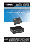
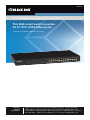
LGB624A
24-Port Web Smart Gigabit Ethernet Switch
This Web smart switch provides
24 10-/100-/1000-Mbps ports.BLACK BOX
®
Supports Gigabit speed on all ports.
Customer
Support
Information
Order toll-free in the U.S.: Call 877-877-BBOX (outside U.S. call 724-746-5500)
FREE technical support 24 hours a day, 7 days a week: Call 724-746-5500 or fax
724-746-0746 • Mailing address: Black Box Corporation, 1000 Park Drive, Lawrence,
PA 15055-1018 • Web site: www.blackbox.com • E-mail: [email protected]
FCC and IC RFI Statements
FEDERAL COMMUNICATIONS COMMISSION and
INDUSTRY CANADA RADIO FREQUENCY INTERFERENCE STATEMENTS
Class B Digital Device. This equipment has been tested and found to comply with
the limits for a Class B computing device pursuant to Part 15 of the FCC Rules.
These limits are designed to provide reasonable protection against harmful
interference in a residential installation. However, there is no guarantee that
interference will not occur in a particular installation. This equipment generates,
uses, and can radiate radio frequency energy, and, if not installed and used in
accordance with the instructions, may cause harmful interference to radio
communications. If this equipment does cause harmful interference to radio or
telephone reception, which can be determined by turning the equipment off
and on, the user is encouraged to try to correct the interference by one of the
following measures:
• Reorient or relocate the receiving antenna.
• Increase the separation between the equipment and receiver.
• Connect the equipment into an outlet on a circuit different from that to which
the receiver is connected.
• Consult an experienced radio/TV technician for help.
CAUTION:
Changes or modifications not expressly approved by the party responsible for
compliance could void the user’s authority to operate the equipment.
To meet FCC requirements, shielded cables and power cords are required to
connect this device to a personal computer or other Class B certified device.
This digital apparatus does not exceed the Class B limits for radio noise emission
from digital apparatus set out in the Radio Interference Regulation of Industry
Canada.
Le présent appareil numérique n’émet pas de bruits radioélectriques dépassant
les limites applicables aux appareils numériques de classe B prescrites dans le
Règlement sur le brouillage radioélectrique publié par Industrie Canada.
Page 2
724-746-5500 | blackbox.com
LGB624A
NOM Statement
Normas Oficiales Mexicanas (NOM)
Electrical Safety Statement
INSTRUCCIONES DE SEGURIDAD
1.Todas las instrucciones de seguridad y operación deberán ser leídas antes de
que el aparato eléctrico sea operado.
2.Las instrucciones de seguridad y operación deberán ser guardadas para referencia futura.
3.Todas las advertencias en el aparato eléctrico y en sus instrucciones de operación deben ser respetadas.
4. Todas las instrucciones de operación y uso deben ser seguidas.
5. El aparato eléctrico no deberá ser usado cerca del agua—por ejemplo,
cerca de la tina de baño, lavabo, sótano mojado o cerca de una alberca, etc.
6. El aparato eléctrico debe ser usado únicamente con carritos o pedestales que sean recomendados por el fabricante.
7. El aparato eléctrico debe ser montado a la pared o al techo sólo como sea recomendado por el fabricante.
8. Servicio—El usuario no debe intentar dar servicio al equipo eléctrico más allá lo descrito en las instrucciones de operación. Todo otro servicio deberá ser referido a personal de servicio calificado.
9. El aparato eléctrico debe ser situado de tal manera que su posición no interfiera su uso. La colocación del aparato eléctrico sobre una cama, sofá, alfombra o superficie similar puede bloquea la ventilación, no se debe colocar en libreros o gabinetes que impidan el flujo de aire por los orificios de ventilación.
10. El equipo eléctrico deber ser situado fuera del alcance de fuentes de calor como radiadores, registros de calor, estufas u otros aparatos (incluyendo amplificadores) que producen calor.
11. El aparato eléctrico deberá ser connectado a una fuente de poder sólo del tipo descrito en el instructivo de operación, o como se indique en el aparato.
LGB624A
724-746-5500 | blackbox.com
Page 3
NOM Statement
12. Precaución debe ser tomada de tal manera que la tierra fisica y la polarización del equipo no sea eliminada.
13. Los cables de la fuente de poder deben ser guiados de tal manera que no sean pisados ni pellizcados por objetos colocados sobre o contra ellos, poniendo particular atención a los contactos y receptáculos donde salen
del aparato.
14. El equipo eléctrico debe ser limpiado únicamente de acuerdo a las recomendaciones del fabricante.
15. En caso de existir, una antena externa deberá ser localizada lejos de las lineas de energia.
16. El cable de corriente deberá ser desconectado del cuando el equipo no sea usado por un largo periodo de tiempo.
17. Cuidado debe ser tomado de tal manera que objectos liquidos no sean derramados sobre la cubierta u orificios de ventilación.
18. Servicio por personal calificado deberá ser provisto cuando:
A: El cable de poder o el contacto ha sido dañado; u
B: Objectos han caído o líquido ha sido derramado dentro del aparato; o
C: El aparato ha sido expuesto a la lluvia; o
D: E l aparato parece no operar normalmente o muestra un cambio en su desempeño; o
E: El aparato ha sido tirado o su cubierta ha sido dañada.
Page 4
724-746-5500 | blackbox.com
LGB624A
Trademarks Used in this Manual
Trademarks Used in this Manual
Black Box and the Double Diamond logo are registered trademarks of
BB Technologies, Inc.
Internet Explorer is a registered trademark of Microsoft Corporation.
UL is a registered trademark of Underwriters’ Laboratories.
Any other trademarks mentioned in this manual are acknowledged to be
the property of the trademark owners.
Disclaimer
Black Box Network Services shall not be liable for damages of any kind, including,
but not limited to, punitive, consequential or cost of cover damages, resulting
from any errors in the product information or specifications set forth in this
document and Black Box Network Services may revise this document at any time
without notice.
LGB624A
724-746-5500 | blackbox.com
Page 5
Table of Contents
Table of Contents
1. Specifications ................................................................................ 8
2. Overview ................................................................................ 9
2.1Introduction................................................................................ 9
2.2Features................................................................................ 9
2.3 What’s Included.............................................................................. 10
2.4 Hardware Description...................................................................... 10
3. Software Description...............................................................................12
3.1 Login ...............................................................................12
3.2 Configuration ...............................................................................13
3.2.1 System ...............................................................................13
3.2.2Ports...............................................................................15
3.2.2.1 Port Configuration.....................................................15
3.2.3VLAN...............................................................................17
3.2.3.1 Port Segmentation (VLAN) Configuration.................17
3.2.3.2VLAN Setup..............................................................17
3.2.3.3VLAN Per Port Configuration....................................18
3.2.4Aggregation.......................................................................... 20
3.2.4.1 Aggregation/Trunking Configuration....................... 20
3.2.5LACP.............................................................................. 20
3.2.5.1 LACP Port Configuration.......................................... 20
3.2.6RSTP...............................................................................21
3.2.6.1 RSTP System Configuration.......................................21
3.2.6.2RSTP Port Configuration........................................... 22
3.2.7 IGMP Snooping.................................................................... 25
3.2.7.1 IGMP Configuration................................................. 25
3.2.8Mirroring
.............................................................................. 26
3.2.8.1 Mirroring Configuration........................................... 26
3.2.9 Quality of Service (QoS)........................................................ 27
3.2.9.1 QoS Configuration................................................... 27
3.2.9.2 QoS Mode: QoS Disabled........................................ 28
3.2.9.3 QoS Mode: 802.1p................................................... 28
3.2.9.4 QoS Mode: DSCP..................................................... 30
3.2.10Storm Control....................................................................... 31
3.2.10.1Storm Control Configuration.................................... 31
3.3Monitoring.............................................................................. 32
3.3.1 Statistics Overview................................................................ 32
3.3.2 Detailed Statistics.................................................................. 32
Page 6
724-746-5500 | blackbox.com
LGB624A
Table of Contents
s
3.3.3 LACP Status.......................................................................... 33
3.3.3.1 LACP Aggregation Overview.................................... 33
3.3.3.2LACP Port Status...................................................... 34
3.3.4 RSTP Status........................................................................... 34
3.3.4.1 RSTP VLAN Bridge Overview.................................... 34
3.3.4.2RSTP Port Status....................................................... 35
3.3.5 IGMP Status.......................................................................... 36
3.3.6VeriPHY.............................................................................. 36
3.3.6.1 VeriPHY Cable Diagnostics....................................... 36
3.3.7Ping.............................................................................. 38
3.3.7.1 Ping Parameters........................................................ 38
4.Maintenance
...............................................................................41
4.1 Warm Restart ...............................................................................41
4.2 Factory Default ...............................................................................41
4.3 Software Upload..............................................................................41
4.4 Configuration File Transfer............................................................... 42
4.5Logout.............................................................................. 42
4.6 Reset Button for the Factory Default Setting................................... 43
LGB624A
724-746-5500 | blackbox.com
Page 7
Chapter 1: Specifications
1. Specifications
Buffer Memory — 500 KB
Compliance — FCC Class B; power supply is UL® Listed
Filtering/Forwarding Rate — 1000-Mbps port: 1,488,000 pps;
100-Mbps port: 148,800 pps;
10-Mbps port: 14,880 pps
Jumbo Frames — 9.6 KB
MAC Address — 8K
Standards — IEEE 802.3 10BASE-T, IEEE 802.3u 100BASE-TX,
IEEE 802.3ab 1000BASE-T, IEEE 802.3x flow control
Transmission Media — 10BASE-T CAT3, 4, 5 UTP/STP;
100BASE-TX CAT5 UTP/STP;
1000BASE-T CAT5e UTP/STP
Connectors — (24) RJ-45, (1) power connector
Indicators — (49) LEDs: Per port: (1) LINK/ACT, (1) 1000M;
Per unit: (1) Power
Power — Internal power supply: Input Voltage: 90–260 VAC, 50–60 Hz;
Input Power/Watts: 20 watts (max.)
Temperature Tolerance — Operating: +32 to +131° F (0 to +55° C);
Storage: -4 to +194° F (-20 to +90° C)
Operating Humidity — 10 to 90% relative humidity (non-condensing)
Size — 1.73"H x 17.32"W x 8.66"D (4.4 x 45 x 22 cm)
Weight — 6.39 lb. (2.9 kg) unit;
6.61 lb. (3 kg) shipping
Page 8
724-746-5500 | blackbox.com
LGB624A
Chapter 2: Overview
2. Overview
2.1 Introduction
The 24-Port Web Smart Gigabit Ethernet Switch provides 24 10-/100-/1000-Mbps
ports. It is designed for easy installation and enables high performance in an
environment where traffic on the network and the number of users increases
continuously. With the newest Gigabit chipset, this 19" Gigabit Ethernet switch
fully supports the highest speed without any problems, even when running
full-duplex fully loaded.
The switch also provides automatic crossover detection on each port, making it
easy to uplink to another switch without using a crossover cable.
This rackmount switch is specifically designed for medium to large workgroups.
It provides smooth network migration and makes it easy to increase network
capacity.
2.2 Features
• Supports real-time status (link, speed, duplex) of each port.
• S upports port setting for enable or disable operation (the first port can’t be
disabled).
• Includes port setting for N-Way or force mode operation.
• Features broadcast storm protection.
• Enables port-based VLAN.
• Supports priority queues for QoS.
• Complies with IEEE 802.3 Ethernet, IEEE 802.3u Fast Ethernet, and IEEE 802.3ab
Gigabit Ethernet standards.
• 24 ports autonegotiate speeds of 10, 100, and 1000 Mbps.
• 19" rackmountable.
• Provides non-blocking and non-head of line blocking full wire-speed
forwarding.
• Store-and-forward operation support.
• Supports 9.6 KB jumbo frames.
• Provides 8K MAC addresses.
• Supports broadcast storm filitering.
LGB624A
724-746-5500 | blackbox.com
Page 9
Chapter 2: Overview
• All ports provide autonegotiation and Auto MDI/MDI-X functions.
• S upports flow control: backpressure for half-duplex and IEEE 802.3x for
full-duplex mode.
• Smart plug and play.
2.3 What’s Included
Your package should contain the following items. If anything is missing
or damaged, contact Black Box Technical Support at 724-746-5500
or [email protected].
• (1) 24-Port Web Smart Gigabit Ethernet Switch
• (1) U.S. power cord
• This user’s manual in PDF format on CD-ROM
• (1) rackmount kit: (2) brackets, (8) screws
2.4 Hardware Description
Figures 2-1 and 2-2 show the front and back panels of the 24-Port Web Smart
Gigabit Ethernet Switch. Table 2-1 describes its components.
1
4
2, 3
4
Figure 2-1. Front panel.
5
6
7
Figure 2-2. Back panel.
Page 10
724-746-5500 | blackbox.com
LGB624A
Chapter 2: Overview
Table 2-1. 24-Port Web Smart Gigabit Ethernet Switch components.
Number
Component
Description
1
(1) Power LED
Lights when power to the unit is on.
2
(24) 1000M LEDs
Light when a port is operating at 1000 Mbps.
3
(24) LINK/ACT LEDs
Light solid when link is up, blink when data is present, and are off
when there is no link.
4
(24) RJ-45 connectors
Connect to 10/100/1000 devices.
5
Air vents
Maintain proper airflow.
6
Power on/off switch
Switches the power to the unit on or off.
7
Power receptacle
Links 90–260-VAC, 50-60-Hz, 20-W internal power supply to
power outlet
LGB624A
724-746-5500 | blackbox.com
Page 11
Chapter 3: Software Description
3. Software Description
This section explains how to set up and manage the switch through the Web user
interface.
3.1 Login
First, open the Web browser, and go to 192.168.2.1. The login screen will appear.
Type in the password (default password: “admin”) to pass the authentication, and
click on the “Apply” button. The following message will appear:
“Password successfully entered.”
Figure 3-1.
Page 12
724-746-5500 | blackbox.com
LGB624A
Chapter 3: Software Description
3.2 Configuration
3.2.1 System
This page shows system configuration information, as illustrated in Figure 3-3.
Figure 3-2. System Configuration screen.
LGB624A
724-746-5500 | blackbox.com
Page 13
Chapter 3: Software Description
•M
AC Address: Displays the unique hardware address assigned by manufacturer
(default).
• S/W Version: Displays the switch’s firmware version.
• H/W Version: Displays the switch’s hardware version.
• DHCP Enabled: Click the box to enable DHCP.
• F allback IP address: Manually assign the IP address that the network is using.
The default IP is 192.168.2.1.
• Fallback Subnet Mask: Assign the subnet mask to the IP address.
• F allback Gateway: Assign the network gateway for industrial switch. The default
gateway is 0.0.0.0.
•M
anagement VLAN: ID of a configured VLAN (1–4096) through which you can
manage the switch. By default, all ports on the switch are members of VLAN 1.
However, you change the management VLAN, the management station must
be attached to a port belonging to this VLAN.
•N
ame: Type in a unique name to identify the switch.
• Password: Type in the new password (the default value is “admin”).
• SNMP Enabled: Enables or disables SNMP on the switch. Supports SNMP version
1 and 2c management clients.
• S NMP Trap Destination: IP address of the trap manager to receive notification
messages from this switch. Traps indicating status changes are issued by the
switch to specified trap managers. You must specify trap managers so that key
events are reported by this switch to your management station.
• S NMP Read Community: A community string that acts like a password and
permits access to the SNMP database on this switch. Authorized management
stations are only able to retrieve MIB objects.
• SNMP Trap Community: Community string sent with the notification operation.
Page 14
724-746-5500 | blackbox.com
LGB624A
Chapter 3: Software Description
3.2.2 Ports
Port Security ensures access to a switch port based on MAC address, limits the
total number of devices from using a switch port, and protects against MAC
flooding attacks.
3.2.2.1 Port Configuration
In Port Configuration, you can set and view the operation mode for each port.
• E nable Jumbo Frames: This switch provides more efficient throughput for large
sequential data transfers by supporting jumbo frames on Gigabit Ethernet ports
up to 9.6 KB. Compared to standard Ethernet frames that run only up to 1.5 KB,
using jumbo frames significantly reduces the per-packet overhead required to
process protocol encapsulation fields.
• Power Saving Mode: Adjusts the power provided to ports based on the length
of the cable used to connect to other devices. Only sufficient power is used to
maintain connection requirements.
• Mode: Manually set the port speed such as auto, 10 half, 10 full, 100 half,
100 full, 1000 full. or disabled. Click on the “Apply” button to complete the
configuration.
Flow Control
Click the check box (x) to enable flow control. If flow control is set to enable, both
parties can send PAUSE frames to the transmitting device(s) if the receiving port is
too busy to handle the amount of data being sent. When it is set to disable, there
will be no flow control on that port. The port will drop packets if the amount of
data becomes too much for the port to handle.
LGB624A
724-746-5500 | blackbox.com
Page 15
Chapter 3: Software Description
Figure 3-3.
Figure 3-4.
Page 16
724-746-5500 | blackbox.com
LGB624A
Chapter 3: Software Description
3.2.3 VLAN
A Virtual LAN (VLAN) is a logical network grouping that limits the broadcast
domain, which would allow you to isolate network traffic, so only the members of
the same VLAN will receive traffic from the members of the same VLAN.
Basically, creating a VLAN from a switch is logically equivalent to reconnecting a
group of network devices to another Layer 2 switch. However, all the network
devices are still plugged into the same switch physically.
3.2.3.1 Port Segmentation (VLAN) Configuration
• VLAN ID: ID of the configured VLAN (1–4096, no leading zeroes).
•V
LAN Configuration List: Lists all the current VLAN groups created for this
system. Up to 16 VLAN groups can be defined. VLAN 1 is the default untagged
VLAN.
Figure 3-5.
3.2.3.2 VLAN Setup
The switch supports up to 16 VLANs based on 802.1Q standard. From the VLAN
Membership page you can create and delete VLANs, and change the VLAN port
membership.
LGB624A
724-746-5500 | blackbox.com
Page 17
Chapter 3: Software Description
Figure 3-6.
3.2.3.3 VLAN Per Port Configuration
The 802.1Q Per Port Configuration page allows you to change the VLAN
parameters for individual ports or trunks. You can configure VLAN behavior for
specific interfaces, including the accepted frame types and default VLAN identifier
(PVID). Each row of the table corresponds to one port or trunk; trunked ports
cannot be configured individually; configure the trunk instead.
Figure 3-7. VLAN per port configuration.
Page 18
724-746-5500 | blackbox.com
LGB624A
Chapter 3: Software Description
• Port/Trunk: The port number of the port or the ID of a trunk.
•V
LAN Aware Enabled: VLAN aware ports are able to use VLAN tagged frames
to determine the destination VLAN of a frame. (Default: Enabled)
•V
LAN aware ports will strip the VLAN tag from received frames and insert the
tag in transmitted frames (except for the PVID). VLAN unaware ports will not
strip the tag from received frames or insert the tag in transmitted frames.
• Ingress Filtering Enabled: If enabled, incoming frames for VLANs that do not
include this ingress port in their member set will be discarded.
(Default: Disabled)
• Packet Type: Sets the interface to accept all frame types, including tagged or
untagged frames, or only tagged frames. (Default: All) If the Packet Type is set
to “All,” the port can accept incoming tagged and untagged packets. Any
received packets that are untagged are assigned to the default VLAN. Any
tagged packets will be dropped unless the port is a member of the VLAN identified by the VLAN tag in the packet. If the Packet Type is set to “Tagged Only,”
the port will drop untagged packets and will only receive tagged packets.
Tagged packets will be dropped unless the port is a member of the VLAN identified by the VLAN tag in the packet. Switches should be connected to each
other with the Packet Type set to “Tagged Only.”
• PVID: The PVID (Port VLAN ID) is associated with untagged, ingress packets. It is
assigned to untagged frames received on the specified interface. The PVID has
no effect on ports that have Packet Type set to “Tagged Only.” (Default PVID: 1)
It is not possible to remove a port from VLAN 1 unless its PVID has been
changed to something other than 1. Outgoing packets are tagged unless the
packet’s VLAN ID is the same as the PVID. When the PVID is set to “None,” all
outgoing packets are tagged.
NOTE: If you select “Tagged Only” mode for a port, we recommend setting the
PVID to “None” as the standard configuration.
LGB624A
724-746-5500 | blackbox.com
Page 19
Chapter 3: Software Description
3.2.4 Aggregation
Port trunk allows multiple links to be bundled together and act as a single physical
link for increased throughput. It provides load balancing, and redundancy of links
in a switched inter-network. Actually, the link does not have an inherent total
bandwidth equal to the sum of its component physical links. Traffic in a trunk is
distributed across an individual link within the trunk in a deterministic method that
called a hash algorithm. The hash algorithm automatically applies load balancing
to the ports in the trunk. A port failure within the trunk group causes the
network traffic to be directed to the remaining ports. Load balancing is
maintained whenever a link in a trunk is lost or returned to service.
3.2.4.1 Aggregation / Trunking Configuration
To assign a port to a trunk, click the required trunk number, and then click
“Apply.”
Figure 3-8. Aggregation/trunking configuration screen.
3.2.5 LACP
IEEE 802.3ad Link Aggregation Control Protocol (LACP) increases bandwidth by
automatically aggregating several physical links together as a logical trunk and
providing load balancing and fault tolerance for uplink connections.
3.2.5.1 LACP Port Configuration
• Port: The port number.
• Enabled: Enables LACP on the associated port.
Page 20
724-746-5500 | blackbox.com
LGB624A
Chapter 3: Software Description
•K
ey Value: Configures a port's LACP administration key. The port administrative
key must be set to the same value for ports that belong to the same link
aggregation group (LAG). If this administrative key is not set when an LAG is
formed (i.e., it has the null value of 0), this key will automatically be set to the
same value as that used by the LAG.
Figure 3-9. LACP port configuration screen.
3.2.6 RSTP
IEEE 802.1w Rapid Spanning tree protocol (LACP) provides a loop-free network
and redundant links to the core network with rapid convergence to ensure faster
recovery from failed links, enhancing overall network stability and reliability.
3.2.6.1 RSTP System Configuration
• System Priority: This parameter configures the spanning tree priority globally for
this switch. The device with the highest priority becomes the STP root device.
However, if all devices have the same priority, the device with the lowest MAC
address will then become the root device.
•H
ello Time: Interval (in seconds) at which the root device transmits a
configuration message (BPDU frame). Number between 1–10 (default is 2).
•M
ax Age: The maximum time (in seconds) a device can wait without receiving a
configuration message before attempting to reconfigure. This also means the
maximum life time for a BPDU frame. Number between 6–40 (default is 20).
LGB624A
724-746-5500 | blackbox.com
Page 21
Chapter 3: Software Description
• F orward Delay: The maximum time (in seconds) the root device will wait before
changing states (i.e., discarding to learning to forwarding). Number between
4–30 (default is 15).
• F orce Version: Set and show the RSTP protocol to use. Normal - use RSTP,
Compatible—compatible with STP.
Figure 3-10. RSTP system configuration.
3.2.6.2 RSTP Port Configuration
• Port: The port ID. It cannot be changed. Aggregations mean any configured
trunk group.
• Enabled: Click on the tick-box to enable/disable the RSTP protocol for the port.
• Edge: Expect the port to be an edge port (linking to an end station) or a link to
another STP device.
• Path Cost: This parameter is used by the STP to determine the best path
between devices. Therefore, lower values should be assigned to ports attached
to faster media, and higher values assigned to ports with slower media. Set the
RSTP pathcost on the port. Number between 0–200000000. 0 means auto
generated pathcost.
Page 22
724-746-5500 | blackbox.com
LGB624A
Chapter 3: Software Description
Figure 3-11. RSTP port configuration screen.
LGB624A
724-746-5500 | blackbox.com
Page 23
Chapter 3: Software Description
Figure 3-12. RSTP system configuration screen.
Figure 3-13. RSTP system configuration screen.
Page 24
724-746-5500 | blackbox.com
LGB624A
Chapter 3: Software Description
3.2.7 IGMP Snooping
IGMP Snooping is the process of listening to IGMP network traffic. IGMP
Snooping, as implied by the name, is a feature that allows a layer 2 switch to
“listen in” on the IGMP conversation between hosts and routers by processing the
layer 3 IGMP packets sent in a multicast network.
When IGMP Snooping is enabled in a switch, it analyzes all IGMP packets
between hosts connected to the switch and multicast routers in the network.
When a switch hears an IGMP report from a host for a given multicast group, the
switch adds the host’s port number to the multicast list for that group. And,
when the switch hears an IGMP Leave, it removes the host’s port from the table
entry.
Prevents flooding of IP multicast traffic, and limits bandwidth intensive video
traffic to only the subscribers.
3.2.7.1 IGMP Configuration
• IGMP Enabled: When enabled, the switch will monitor network traffic to
determine which hosts want to receive multicast traffic.
• Router Ports: Set if ports are connecting to the IGMP administrative routers.
• Unregistered IPMC Flooding enabled: Set the forwarding mode for unregistered
(not joined) IP multicast traffic. The traffic will flood when enabled, and forward
to router-ports only when disabled.
• IGMP Snooping Enabled: When enabled, the port will monitor network traffic
to determine which hosts want to receive the multicast traffic.
• IGMP Querying Enabled: When enabled, the port can serve as the Querier,
which is responsible for asking hosts if they want to receive multicast traffic.
Figure 3-14.
LGB624A
724-746-5500 | blackbox.com
Page 25
Chapter 3: Software Description
3.2.8 Mirroring
Port Mirroring is used on a network switch to send a copy of network packets
seen on one switch port (or an entire VLAN) to a network monitoring connection
on another switch port. This is commonly used for network appliances that
require monitoring of network traffic, such as an intrusion-detection system.
3.2.8.1 Mirroring Configuration
• Port to Mirror to: The port that will “duplicate” or “mirror” the traffic on the
source port. Only incoming packets can be mirrored. Packets will be dropped
when the available egress bandwidth is less than ingress bandwidth.
• P orts to Mirror: Select the ports that you want to mirror from this section of the
page. A port will be mirrored when the “Mirroring Enabled” check-box is
checked.
Figure 3-15. Mirroring configuration screen.
Page 26
724-746-5500 | blackbox.com
LGB624A
Chapter 3: Software Description
Figure 3-16. Mirroring configuration screen.
3.2.9 Quality of Service (QoS)
In QoS Mode, select QoS Disabled, 802.1p, or DSCP to configure the related
parameters.
3.2.9.1 QoS Configuration
• S trict: Services the egress queues in sequential order, transmitting all traffic in
the higher priority queues before servicing lower priority queues.
•W
RR: Weighted Round-Robin shares bandwidth at the egress ports by using
scheduling weights with default values of 1, 2, 4, 8 for queues 0 through 7,
respectively. (This is the default selection.)
NOTE: WRR can only be selected if Jumbo Frame mode is disabled on the Port
Configuration page.
LGB624A
724-746-5500 | blackbox.com
Page 27
Chapter 3: Software Description
Figure 3-17. QoS configuration screen.
3.2.9.2 QoS Mode: QoS Disabled
When the QoS Mode is set to QoS Disabled, the following table is displayed.
Figure 3-18. QoS disabled screen.
3.2.9.3 QoS Mode: 802.1p
Packets are prioritized using the 802.1p field in the VLAN tag. This field is three
bits long, representing the values 0–7. When the QoS Mode is set to 802.1p, the
802.1p Configuration table appears, allowing you to map each of the eight 802.1p
values to a local priority queue (low, normal, medium or high). The default settings are shown below.
When the QoS Mode is set to 802.1p, the 802.1p Configuration table is displayed
as shown next.
Page 28
724-746-5500 | blackbox.com
LGB624A
Chapter 3: Software Description
Figure 3-19. QoS configuration custom selected.
Figure 3-20.
LGB624A
724-746-5500 | blackbox.com
Page 29
Chapter 3: Software Description
3.2.9.4 QoS Mode: DSCP
DSCP: Packets are prioritized using the DSCP (Differentiated Services Code Point)
value. The Differentiated Services Code Point (DSCP) is a six-bit field that is
contained within an IP (TCP or UDP) header. The six bits allow the DSCP field to
take any value in the range 0–63. When QoS Mode is set to DSCP, the DSCP
Configuration table is displayed, allowing you to map each of the DSCP values to
a hardware output queue (low, normal, medium or high). The default settings
map all DSCP values to the high priority egress queue. Users can use the Prioritize
Traffic drop-down list to quickly set the values in the DSCP Configuration table to
a common priority queue. Use Custom if you want to set each value individually.
When the QoS Mode is set to DSCP, the DSCP Configuration table is displayed as
shown below.
Figure 3-21.
Page 30
724-746-5500 | blackbox.com
LGB624A
Chapter 3: Software Description
Figure 3-22.
3.2.10 Storm Control
Broadcast storms may occur when a device on your network is malfunctioning, or
if application programs are not well designed or properly configured. If there is
too much broadcast traffic on your network, performance can be severely
degraded or everything can come to complete halt.
You can protect your network from broadcast storms by setting a threshold for
broadcast traffic for each port. Any broadcast packets exceeding the specified
threshold will then be dropped.
3.2.10.1 Storm Control Configuration
There are three type of traffic that can be rate limited, including broadcast
multicast frame and Flooded Uncast Rate.
Figure 3-23.
• Enable Rate Limit: Click the check box to enable storm control.
LGB624A
724-746-5500 | blackbox.com
Page 31
Chapter 3: Software Description
•R
ate (number of frames per second): The Rate field is set by a single drop-down
list. The same threshold is applied to every port on the switch. When the
threshold is exceeded, packets are dropped, irrespective of the flow-control
settings.
• Web: Click PORTS, Storm Control. This page enables you to set the broadcast
storm control parameters for every port on the switch.
3.3 Monitoring
3.3.1 Statistic Overview
Statistic Overview for all ports
User can mirror traffic from any source port to a target port for real-time analysis
the following figures shows clearly the statistics overview.
Figure 3-24.
3.3.2 Detailed Statics
Figure 3-25.
Page 32
724-746-5500 | blackbox.com
LGB624A
Chapter 3: Software Description
3.3.3 LACP Status
3.3.3.1 LACP Aggregation Overview
Figure 3-26.
• Port: The port number.
• Port Active: Shows if the port is a member of an active LACP group.
• P artner Port Number: A list of the ports attached at the remote end of this LAG
link member.
• Operational Port Key: Current operational value of the key used by this LAG.
LGB624A
724-746-5500 | blackbox.com
Page 33
Chapter 3: Software Description
3.3.3.2 LACP Port Status
Figure 3-27. LACP port status screen.
3.3.4 RSTP Status
3.3.4.1 RSTP VLAN Bridge Overview
Figure 3-28. RSTP VLAN bridge overview.
• Hello Time: Interval (in seconds) at which the root device transmits a
configuration message.
• Max Age: The maximum time (in seconds) a device can wait without receiving a
configuration message before attempting to reconfigure. All device ports (except
for designated ports) should receive configuration messages at regular intervals.
Any port that age out STA information (provided in the last configuration
message) becomes the designated port for the attached LAN. If it is a root port,
a new root port is selected from among the device ports attached to the
network.
Page 34
724-746-5500 | blackbox.com
LGB624A
Chapter 3: Software Description
• F wd Delay: The maximum time (in seconds) the root device will wait before
changing states (i.e., discarding to learning to forwarding). This delay is required
because every device must receive information about topology changes before
it starts to forward frames. In addition, each port needs time to listen for
conflicting information that would make it return to a discarding state;
otherwise, temporary data loops might result.
• Topology: Indicates if spanning tree topology is steady or undergoing
reconfiguration. (The time required for reconfiguration is extremely short,
so no values other than “steady” state are likely to be seen in this field.)
• Root ID: The priority and MAC address of the device in the Spanning Tree that
this switch has accepted as the root device, and the port connected to the root
device.
3.3.4.2 RSTP Port Status
Figure 3-29. RSTP port status screen.
• Port/Group: The number of a port or the ID of a static trunk.
• P ath Cost: The cost for a packet to travel from this port to the root in the
current Spanning Tree configuration. The slower the media, the higher the cost.
• Edge Port: Shows if this port is functioning as an edge port, either through
manual selection (see the RSTP Port Configuration table) or auto-detection.
NOTE: If the switch detects another bridge connected to this port, the manual
setting for Edge Port will be overridden, and the port will instead function
as a point-to-point connection.
LGB624A
724-746-5500 | blackbox.com
Page 35
Chapter 3: Software Description
• P 2P Port: Shows if this port is functioning as a Point-to-Point connection to
exactly one other bridge. The switch can automatically determine if the interface
is attached to a point-to-point link or to shared media. If shared media is
detected, the switch will assume that it is connected to two or more the switch
will assume that it is connected to two or more bridges.
• Protocol: Shows the spanning tree protocol functioning on this port, either STP
or STP (that is, STP-compatible mode).
3.3.5 IGMP Status
IGMP Status shows the IGMP Snooping statistics for the entire switch.
• VLAN ID: VLAN ID number.
• Querier: Show whether Querying is enabled.
• Queries transmitted: Show the number of transmitted Query packets.
• Queries received: Show the number of received Query packets.
• v1 Reports: Show the number of received v1 Report packets.
• v2 Reports: Show the number of received v2 Report packets.
• v3 Reports: Show the number of received v2 Report packets.
• v3 Leave: Show the number of v3 leave packets received.
Figure 3-30. IGMP status screen.
3.3.6 VeriPHY
3.3.6.1 VeriPHY Cable Diagnostics
Users can perform cable diagnostics for all ports or selected ports to diagnose any
cable faults (short, open, etc..) and feedback a distance to the fault.
• Cable Diagnostics: Cable diagnostics is performed on a per-port basis. Select the
port number from the drop-down list.
Page 36
724-746-5500 | blackbox.com
LGB624A
Chapter 3: Software Description
•C
able Status: Shows the cable length, operating conditions and isolates a variety
of common faults that can occur on Category 5 twisted pair cabling.
Figure 3-31.
Figure 3-32.
LGB624A
724-746-5500 | blackbox.com
Page 37
Chapter 3: Software Description
Figure 3-33.
Figure 3-34.
3.3.7 Ping
This command sends ICMP echo request packets to another node on the
network.
3.3.7.1 Ping Parameters
• Target IP Address: IP address of the host.
Page 38
724-746-5500 | blackbox.com
LGB624A
Chapter 3: Software Description
• Count: Number of packets to send. (Range: 1–20)
• Time Out: setting the time period the host will Ping.
Use the ping command to see if another site on the network can be reached.
The following are some results of the ping command:
•N
ormal response: The normal response occurs in one to ten seconds, depending
on network traffic.
•D
estination does not respond: If the host does not respond, a “timeout”
appears in ten seconds.
•D
estination unreachable: The gateway for this destination indicates that the
destination is unreachable.
• Network or host unreachable: The gateway found no corresponding entry in the
route table.
Press <Esc> to stop pinging.
'
Figure 3-35.
LGB624A
724-746-5500 | blackbox.com
Page 39
Chapter 3: Software Description
Figure 3-36.
Figure 3-37.
Page 40
724-746-5500 | blackbox.com
LGB624A
Chapter 4: Maintenance
4. Maintenance
4.1 Warm Restart
Press the “Yes” button to restart the switch. The reset will be complete when the
power lights stop blinking.
Figure 4-1. Warm Reset screen.
4.2 Factory Default
This function forces the switch back to the original factory settings. To reset the
switch, select “Reset to Factory Defaults” from the drop-down list and click
“Apply.” The LAN IP Address, Subnet Mask and Gateway IP Address will be reset
to their factory default settings.
Figure 4-2. Factory Default screen.
4.3 Software upload
Select “Upgrade Firmware” from the Tools drop-down list then click on the
“Browse” button to select the firmware file. Click the APPLY button to upgrade
the selected switch firmware file. User can download firmware files for user’s
switch from http://ftp.blackbox.com/lan/switches/FW/most%20current%20fw.
LGB624A
724-746-5500 | blackbox.com
Page 41
Chapter 4: Maintenance
Figure 4-3.
4.4 Configuration File Transfer
Configuration file transfer allows you to save the switch’s current configuration
or restore a previously saved configuration back to the device. Configuration files
can be saved to any location on the web management station. “Upload” the
configuration file to save a configuration or “Download” to restore a
configuration. Use the “Browse” button to choose a file location on the Web
management station, or to find a saved configuration file.
Figure 4-4.
4.5 Logout
The administrator has write access for all parameters governing the onboard
agent. The user should assign a new administrator password as soon as possible,
and store it in a safe place.
Page 42
724-746-5500 | blackbox.com
LGB624A
Chapter 4: Maintenance
4.6 Reset Button for the Factory Default Setting
Follow these steps to reset the Web Smart Switch back to the original default:
STEP 1: Turn on the Web Smart Switch
STEP 2: Press and hold the reset button continuously for 5 seconds and release
the reset button.
STEP 3: The switch will reboot for 20 seconds and the switch configuration will
revert back to the default setting.
LGB624A
724-746-5500 | blackbox.com
Page 43
Black Box Tech Support: FREE! Live. 24/7.
Tech support the
way it should be.
Great tech support is just 60 seconds away at
724-746-5500 or blackbox.com.
About Black Box
Black Box provides an extensive range of networking and infrastructure products.
You’ll find everything from cabinets and racks and power and surge protection
products to media converters and Ethernet switches all supported by free, live 24/7
Tech support available in 60 seconds or less.
© Copyright 2014. Black Box Corporation. All rights reserved.
LGB624A, version 2
724-746-5500 | blackbox.com