1
ALE
Design • Print • Trace
18/06/2010
MasterPad Distributor Manual
Table of contents
Table of contents....................................................................................................................ii
Disclaimer...............................................................................................................................3
Warnings................................................................................................................................ 3
1.Description.......................................................................................................................... 4
1.Contents of the box.........................................................................................................4
2.Specifications..................................................................................................................4
3.Power..............................................................................................................................4
4.Dimensions and weight...................................................................................................5
5.Operating conditions.......................................................................................................5
2.Installation........................................................................................................................... 8
1.Enclosure mounting........................................................................................................8
2.Photocell and encoder..................................................................................................10
3.Print-heads....................................................................................................................10
4.Power supply................................................................................................................11
3.Controller use....................................................................................................................12
1.Navigation overview......................................................................................................12
2.Setup Wizard................................................................................................................14
3.Load a CodeX file via USB...........................................................................................15
4.Load a CodeX file via Ethernet.....................................................................................15
5.Purging and inking........................................................................................................15
4. Reference.........................................................................................................................16
1. Info screen...................................................................................................................16
2. Edit tool........................................................................................................................16
3. USB Keyboard.............................................................................................................16
4. CodeLoad....................................................................................................................17
5. Hot plugging capabilities..............................................................................................17
6. Network configuration..................................................................................................17
7. Direct connection to a PC via Ethernet........................................................................18
8. Print-head configuration screen...................................................................................18
9. Wifi...............................................................................................................................18
10. Dongle........................................................................................................................18
11. Menu Customisation..................................................................................................19
12. Ink low detection........................................................................................................19
MasterPad Distributor Manual
ii
ALE
Design • Print • Trace
18/06/2010
Disclaimer
This manual contains instructions for installation and use of the
ALE
MasterPad controller. Read it carefully before performing any manipulation.
All information written in this Distributor Manual was correct at the time indicated in
the version table below. However, the continual enhancement of our products may result
in some differences existing between the information contained in this document and
your equipment.
Copyright © 2010 ALE sarl, all rights reserved. Reproducing this manual in whole or
part without permission is expressly prohibited.
RiX® and TraceX® are registered trademarks of ALE sarl.
All trademarks in this document belong to their respective owners.
Version history:
Date:
Revision:
19/01/10
First version
18/06/10
#1
Modifications:
Author:
AF
Minor corrections
AF
Warnings
The ALE MasterPad is an electric device, and as such, basic safety
precautions should always be followed, including the following:
–
to protect against fire and electric shock, do not place cord, plugs or device in
water or other liquid.
–
Do not operate the device if the cord or plug is damaged
–
Do not operate the device after a suspicious malfunction or if damaged
–
Electrical equipment can be hazardous : ensure a good quality and earthed supply
–
Do not use the device for other than intended use
MasterPad Distributor Manual
3
ALE
Design • Print • Trace
18/06/2010
1. Description
The ALE MasterPad controller is designed to control from one to eight ALE inkjet printheads (their intended use is described in their own user manual). It can also be
connected
with
devices
compatible
with
the
description
given
in
fig.
2.
Using this controller outside of its intended use range can result in damages. Please
contact ALE for any question.
1. Contents of the box
1x MasterPad
1x power supply cord
1x mounting bracket
1x CD-Rom with Codex software and manuals
2. Specifications
Stainless steel enclosure
IP64 on 5 sides
3 status LEDs (On, Ready, Alarm)
CPU: Intel Xscale PXA270 at 312MHz
RAM: 64MB SDRAM
Storage memory:128MB (32MB for message storage)
Screen: 3,5" 320x240p touch sensitive
Wifi Antenna : yes (not activated yet)
1x USB Host port (for USB memory key or keyboard)
1x Ethernet 10/100 baseT RJ45 port
1x Photocell connector
1x RS232 9pin male port
1x AUX 15pin female port
1x encoder 9pin female port
2, 4 or 8 IEEE1394 "hot-pluggable" print-head connectors
Option : RS232#2, Encoder#2, Photocell#2
3. Power
Power requirements : 75W 90/250VAC 50-60Hz.
Recommended fuse : 2A anti-surge.
MasterPad Distributor Manual
4
ALE
Design • Print • Trace
18/06/2010
4. Dimensions and weight
Dimensions:
Length : 300mm
Width : 200mm
Height : 115mm
Weight : 3,1kg
5. Operating conditions
Operating conditions:
Humidity range : 5 to 65% RHL
Temperature range : +5 to +40° Centigrade
Ensure an air gap of 3,5mm between the base and the mounting surface for
heat dissipation
MasterPad Distributor Manual
5
ALE
Design • Print • Trace
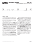
Status LEDs
Function keys
18/06/2010
3,5" touch
sensitive LCD
screen
"Cancel" key
"OK" key
Connector panel
Power supply connector
fig. 1: MasterPad controller description
MasterPad Distributor Manual
6
ALE
Design • Print • Trace
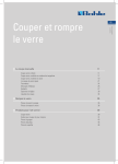
18/06/2010
fig. 2: MasterPad connector panel
MasterPad Distributor Manual
7
ALE
Design • Print • Trace
18/06/2010
2. Installation
Note : before installing the system on a production line, do a test setup on a
bench or a table to ensure that everything works correctly.
1. Enclosure mounting
The MasterPad can be mounted on a vertical mast along the conveyor using
the included bracket(fig. 3). This bracket is compatible with Norcan® 90mm
wide profile (45mm between mounting rails).
4x M5x10mm Hex.
screws
M8 Hex. screw
M5 Hex. screw
fig. 3: MasterPad mounting
Alternatively the MasterPad can be mounted in a custom way using the
mounting M5 holes under the enclosure (dimensions given in fig. 4)
Ensure an air gap of 3,5mm between the base and the mounting
surface for heat dissipation.
MasterPad Distributor Manual
8
ALE
Design • Print • Trace
18/06/2010
fig. 4: MasterPad base dimensions
2. Photocell and encoder
The photocell and encoder should be mounted along the production line as
described for example in Z-series Operator Manual (section 3.3.1).
3. Print-heads
Please refer to the user manual of the ALE print-head to be used with the
MasterPad : it contains information regarding installation, printing heights, inks
etc...
The print-head is connected to the MasterPad via a standard 6-pin IEEE1394
cable (fig. 5). One of the features of the IEEE1394 standard is that it is
possible to disconnect or reconnect a print-head while the controller is running
without risking damaging it ("Hot connect" feature).
The IEEE1394 connectors of the MasterPad are used in a specific way,
which does not follow the FireWire standard. Therefore, the IEEE1394
connectors can be used ONLY to connect ALE compatible print-heads.
Trying to connect any other device with an IEEE1394 cable might
damage it!
MasterPad Distributor Manual
9
ALE
Design • Print • Trace
18/06/2010
fig. 5: Connect Print-Head to MasterPad with IEEE1394 6-pin cable
4. Power supply
The MasterPad needs an IEC compatible power cord. Before plugging in the
controller, please refer to the specifications regarding power requirements.
MasterPad Distributor Manual
10
ALE
Design • Print • Trace
18/06/2010
3. Controller use
1. Navigation overview
The MasterPad has a tactile 3,5" screen, rounded by a keypad. The keypad has
function keys (F1 to F8) around the screen to select items on the screen. The
keypad also has keys to enter or delete characters. See illustration on fig. 6.
Touchscreen area
Functions keys
Cancel
Ok
Delete
Upper caps/lower
caps/digits
Arrows
fig. 6: MasterPad keypad and touchscreen
MasterPad Distributor Manual
11
ALE
Design • Print • Trace
18/06/2010
Items on the screen can be selected either
by touching them or pressing the function
key next to it (fig. 7).
fig. 7: Example : to go into "info", either
press F3 or touch the "i" icon on the
screen
In any situation, pressing the "Cancel" key.
previous menu and cancel the current action.
.will bring you back to the
In the main menu, the. .icon gives access to information about the
controller. In any other screen where this icon appears, it gives access to
contextual help.
A diagram of all the menus is available in fig. 15
2. Setup Wizard
To ease the installation of a printing system driven by a MasterPad, a Setup
Wizard is accessible from the main screen(fig. 8).
This wizard is designed to set all the basic settings in one operation. Please
refer to the demo video called MasterPad_Setup_Wizard.htm in the directory
fig. 8: Begin the setup wizard process
"MasterPad videos" in the documentation section of the CD-ROM or on ALE's
website (click here).
MasterPad Distributor Manual
12
ALE
Design • Print • Trace
18/06/2010
3. Load a CodeX file via USB
Codex files created on a Windows PC can be transferred to the MasterPad via a
USB
memory
key.
Please
refer
to
the
demo
video
called
MasterPad_Load_file_from_USB.htm in the directory "MasterPad videos" in the
documentation section of the CD-ROM or on ALE's website (click here).
4. Load a CodeX file via Ethernet
Codex files created on a Windows PC can be transferred to the MasterPad via
the
network.
Please
refer
to
the
demo
video
called
MasterPad_Load_file_from_Ethernet.htm in the directory "MasterPad videos" in
the documentation section of the CD-ROM or on ALE's website (click here).
5. Purging and inking
Please refer to the manual of the print-head to be used with the MasterPad.
The MasterPad has a purge menu, similar to the one of the J-series. To access
it, first go to the "Print Mode" menu on the main screen (fig. 6). In that menu
select a message then touch the arrow- -or press F5. On the appearing
screen, the purge menu is accessed by touching its icon- -or pressing F6.
The functions of this menu are the same as in the J-series controller.
MasterPad Distributor Manual
13
ALE
Design • Print • Trace
18/06/2010
4. Reference
1. Info screen
The info screen contains information regarding the status of the MasterPad
(memory usage, IP address, serial number, options, connected heads...). It
can be accessed by touching the- -icon or pressing F3 on the main
screen(fig. 9).
fig. 9: info screen
2. Edit tool
It is a tool created to allow basic messages editing directly on the MasterPad.
Please refer to the demo video called Edit_menu.htm in the directory
"MasterPad videos" in the documentation section of the CD-ROM or on ALE's
website (click here).
3. USB Keyboard
The MasterPad has a host USB port that can be used either to connect a
memory key, or a USB keyboard. The keyboard can be used to enter text and
navigate through the menus, using F1 to F8. The "return" key does the
same asand "Esc" acts as- .Everything can be commanded from the
USB keyboard, except test print.
When a USB keyboard is connected, an icon shows it on the main screen(fig.
10).
MasterPad Distributor Manual
14
ALE
Design • Print • Trace
18/06/2010
fig. 10: USB keyboard connected
4. CodeLoad
As in the J-series, it is a function to update the MasterPad software. Please
refer to the technical bulletin TB061D available from ALE's website (distributors
section).
5. Hot plugging capabilities
With the MasterPad, compatible ALE print-heads are now connected using a 6
pin female IEEE1394 cable.
With this standard it is possible to plug or unplug a print-head from the
controller even while it is powered, without any risk to the print-head or the
controller. The MasterPad software instantly detects changes in the printhead(s) configuration.
USB devices that can be plugged into the MasterPad can also be connected and
removed at will.
This capability does not apply to other devices that can be connected to
the MasterPad (photocell, RS232...).
The IEEE1394 connectors of the MasterPad are used in a specific way,
which does not follow the FireWire standard. Therefore, the IEEE1394
connectors can be used ONLY to connect ALE compatible print-heads.
Trying to connect any other device with an IEEE1394 cable might
damage it!
6. Network configuration
The MasterPad can be connected to a TCP/IP network via its Ethernet
connection. The network settings are in Settings > Installation functions > I/O,
Ethernet, RS232, LCD.
MasterPad Distributor Manual
15
ALE
Design • Print • Trace
18/06/2010
7. Direct connection to a PC via Ethernet
The MasterPad can be connected directly to a PC using a cross RJ45 cable and
its Ethernet connection. In that case it is needed to set DHCP (automatic IP
address) OFF in both the PC and MasterPad, and set fixed IP addresses in both
the MasterPad and PC. This action is suited for experienced users. Please refer
to the PC documentation for instructions on operating without a DHCP server.
8. Print-head configuration screen
This screen is part of the setup wizard process. It is a screen with two tables.
The left one shows the list of print-heads connected to the MasterPad controller
(the list is populated while the MasterPad scans all the ports). In the right tab
is a list of configurations to choose from.
The
sign. .shows that the selected configuration does not match detected
print-heads (fig. 11). This sign can be ignored in cases where print-heads have
been temporarily removed.
fig. 11: Print-head configuration screen (the current selected configuration is "1x18mm",
and 1x54mm is recommended)
9. Wifi
The MasterPad comes with a Wifi antenna. The Wifi functions are not
implemented yet and will be in the future.
10. Dongle
Some options (EntriX, VerifiX and RiX) are not activated by default. To activate
any or a combination of these options, it is necessary to plug a USB dongle
into the MasterPad. It can be connected into the external USB port or an
internal one (please refer to technical bulletin TB062P for the mounting
procedure). This leaves the external USB port free for another USB device.
No dongle is required for default operation.
MasterPad Distributor Manual
16
ALE
Design • Print • Trace
18/06/2010
11. Menu Customisation
This feature is not implemented yet.
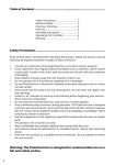
12. Ink low detection
When a print-head sends an ink-low detection message to the controller, the
red ALARM LED (fig. 1) is turned on, and a sign is shown in the home
screen(fig. 12). The Print Mode screen also shows an icon indicating which
print-head(s) sent the alarm (fig. 13). If the print-head timeout is reached, the
icon changes to red and the printing is suspended(fig. 14).
fig. 12: Ink low icon on the home screen
fig. 13: Ink low detected (Alarm LED is
RED)
MasterPad Distributor Manual
fig. 14: Ink low timeout reached : printing
stopped!
17
ALE
Design • Print • Trace
18/06/2010
fig. 15: MasterPad menu layout
MasterPad Distributor Manual
18