1
NEC Technologies
Projector
User’s Manual
MultiSync LT 100
®
™
Ultra-Portable Projector
Ultra-Portable Projector
NEC Technologies, Inc.
1250 N. Arlington Heights Road, Suite 500
Itasca, Illinois 60143-1248
Part No. 78409941
Printed in Japan
I M P O R T A N T
I N F O R M A T I O N
Precautions
1
CAUTION
Please read this manual carefully before using your NEC MultiSync
LT100 Projector and keep the manual handy for future reference.
Your serial number is located beneath the main power switch on the back of
your MultiSync LT100. Record it here:
CAUTION
LASER RADIATIONDO NOT STARE INTO BEAM
TO PREVENT SHOCK, DO NOT OPEN THE CABINET. NO USER-SERVICEABLE PARTS INSIDE.
REFER SERVICING TO QUALIFIED NEC SERVICE
PERSONNEL.
This symbol warns the user that uninsulated voltage
within the unit may be sufficient to cause electrical
shock. Therefore, it is dangerous to make any kind
of contact with any part inside of the unit.
This symbol alerts the user that important information concerning the operation and maintenance of
this unit has been provided. The information should
be read carefully to avoid problems.
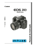
WAVE LENGTH: 670 nm
MAX. OUTPUT: 1 mW
CLASS II LASER PRODUCT
WARNING
TO PREVENT FIRE OR SHOCK, DO NOT EXPOSE THIS UNIT
TO RAIN OR MOISTURE. DO NOT USE THIS UNIT’S
GROUNDED PLUG WITH AN EXTENSION CORD OR IN AN
OUTLET UNLESS ALL THREE PRONGS CAN BE FULLY INSERTED. DO NOT OPEN THE CABINET. THERE ARE HIGHVOLTAGE COMPONENTS INSIDE. ALL SERVICING MUST BE
DONE BY QUALIFIED NEC SERVICE PERSONNEL.
DOC Compliance Notice
This Class A digital apparatus meets all requirements of the Canadian Interference-Causing Equipment Regulations.
RF Interference
WARNING
The Federal Communications Commission does not allow any
modifications or changes to the unit EXCEPT those specified by
NEC Technologies in this manual. Failure to comply with this
government regulation could void your right to operate this equipment.
This equipment has been tested and found to comply with the limits
for a Class A digital device, pursuant to Part 15 of the FCC Rules.
These limits are designed to provide reasonable protection against
harmful interference in a commercial installation. This equipment
generates, uses and can radiate radio frequency energy and, if not
installed and used in accordance with the instructions, may cause
harmful interference to radio communications. Operation of this
equipment in a residential area is likely to cause harmful interference in which case the user will be required to correct the interference at their own expense.
2
3
Important Safeguards
These safety instructions are to ensure the long life of your projector and to
prevent fire and shock. Please read them carefully and heed all warnings.
Installation
1. For best results, use your projector in a darkened room.
2. Place the projector on a flat, level surface in a dry area away from dust and
moisture.
3. Do not place your projector in direct sunlight, near heaters or heat radiating
appliances.
7. If installing the projector on the ceiling:
a. The ceiling must be strong enough to support the projector and the
installation must be in accordance with any local building codes.
b. The projector must be installed by qualified NEC service personnel.
Power Supply
4. Exposure to direct sunlight, smoke or steam can harm internal components.
1. The projector is designed to operate on a power supply of 100-120 or 220-240
V 50/60 Hz AC. Ensure that your power supply fits this requirement before
attempting to use your projector.
5. Handle your projector carefully. Dropping or jarring can damage internal
components.
2. Handle the power cable carefully and avoid excessive bending. A damaged
cord can cause electric shock or fire.
6. Do not place heavy objects on top of the projector.
3. If the projector is not to be used for an extended period of time, disconnect the
plug from the power outlet.
Cleaning
Fire and Shock Precautions
1. Unplug the projector before cleaning.
2. Clean the cabinet periodically with a damp cloth. If heavily soiled, use a mild
detergent. Never use strong detergents or solvents such as alcohol or thinner.
3. Use a blower or lens paper to clean the lens, and be careful not to scratch or
mar the lens.
1. Ensure that there is sufficient ventilation and that vents are unobstructed to
prevent the build-up of heat inside your projector. Allow at least 3 inches
(10cm) of space between your projector and a wall.
Lamp Replacement
• Perform lamp replacement in accordance with the instructions on page 77.
• Be sure to replace the lamp when the Status light comes on. If you continue
to use the lamp after 1000 hours of use, the lamp bulb may shatter, and pieces
of glass may be scattered in the lamp case. Do not touch them as the pieces of
glass may cause injury. If this happens, contact your NEC dealer for lamp
replacement.
• Allow a minimum of ONE minute to elapse between turning the lamp off and
on. High voltage is applied to the lamp immediately when the power is turned
on. Therefore turning the power off and quickly back on may shorten the life
of your lamp and result in damage to your projector.
2. Prevent foreign objects such as paper clips and bits of paper from falling into
your projector. Do not attempt to retrieve any objects that might fall into your
projector. Do not insert any metal objects such as a wire or screwdriver into
your project. If something should fall into your projector, disconnect it
immediately and have the object removed by a qualified NEC service person.
3. Do not place any liquids on top of your projector.
• Do not look into the lens while the projector is on. Serious
damage to your eyes could result.
• Do not look into the laser pointer while it is on and do not point
the laser beam at another person. Serious injury could result.
4
5
ATTENTION
RISQUE D’ELECTROCUTION NE PAS OUVRIR
ATTENTION
RAYONNEMENT LASER NE PAS
REGARDER DANS LE FAISCEAU
Ce symbole a pour but de prévenir l’utilisateur de la
présence d’une tension dangereuse, non isolée se
trouvant à l’intérieur de l’appareil. Elle est d’une
intensité suffisante pour constituer un risque
d’électrocution. Eviter le contact avec les pièces à
l’intérieur de cet appareil.
Ce symbole a pour but de prévenir l’utilisateur de la
présence d’importantes instructions concernant
l’entretien et le fonctionnement de cet appareil. Par
conséquent, elles doivent être lues attentivement
afin d’éviter des problèmes.
LONGUEUR D’ONDE: 670 nm
MAX. SORTIE: 1 mW
APPREIL A LASER DE CLASSE 2
AVERTISSEMENT
AFIN DE REDUIRE LES RISQUES D’INCENDIE OU
D’ELECTROCUTION, NE PAS EXPOSER CET APPAREIL A LA
PLUIE OU A L’HUMIDITE. AUSSI, NE PAS UTILISER LA FICHE
POLARISEE AVEC UN PROLONGATEUR OU UNE AUTRE
PRISE DE COURANT SAUF SI CES LAMES PEUVENT ETRE
INSEREES A FOND. NE PAS OUVRIR LE COFFRET, DES
COMPOSANTES HAUTE TENSION SE TROUVENT A
L’INTERIEUR. LAISSER A UN PERSONNEL QUALIFIE LE
SOIN DE REPARER CET APPAREIL.
Importantes précautions de sécurité
Les points suivants sont des précautions de sécurité importantes destinées à
garantir une longue durée de service du projecteur et afin d’éviter un incendie
et des risques d’électrocution. S’assurer de lire attentivement ces précautions de
sécurité et respecter tous les avertissements décrits ci-dessous.
Installation
1. Pour un fonctionnement optimal, utiliser le projecteur dans une pièce sombre.
2. Placer le projecteur sur une surface à niveau et dans un endroit sec exempt de
poussières et d’humidité.
3. Ne pas placer le projecteur en plein soleil, près d’appareils ménagers ou
d’autres appareils de chauffage.
DOC avis de conformation
DOC avis de conformation
Cet appareil numérique de la classe A respecte toutes les exigences du
Règlement sur le Matériel Brouilleur du Canada.
6
7
4. La fumée, la vapeur et l’exposition aux rayons directs du soleil risquent de
détériorer sérieusement les composantes internes.
5. Eviter des manipulations brusques lors du déplacement du projecteur, car un
choc violent pourrait endommager les composantes internes.
6. Ne pas deposer d’objets lourds sur le dessus du projecteur.
7. Lors de l’installation du projecteur au plafond, respecter les instructions
suivantes.
a. Le plafond doit être suffisamment solide pour supporter le poids du
projecteur et il doit être installé selon les codes de construction locaux.
b. Le projecteur doit être installé par un personnel qualifié.
Alimentation
1. Le projecteur est conçu pour fonctionner à 100-120 ou 220-240VCA 50/
60Hz. S’assurer que la tension d’alimentation locale satisfait cette exigence
avant d’utiliser le projecteur.
3. Si le projecteur n’est pas utilisé pendant une période prolongée, retirer la fiche
de la prise secteur.
Nettoyage
1. Débrancher le projecteur de la prise d’alimentation avant le nettoyage.
2. Nettoyer régulièrement le coffret avec un chiffon doux. S’il y a des taches
tenaces, utiliser une solution d’un détergent doux. Ne jamais utiliser de
détergents puissants ou des solvants, tel que l’alcool ou un diluant pour
nettoyer le projecteur.
3. Utiliser un appareil diffuseur chauffant ou du papier de nettoyage de lentille
disponible dans le commerce pour nettoyer la lentille.
Ne pas frapper ou rayer la surface de la lentille, car des défauts risquent de se
produire sur la surface de la lentille.
2. Manipuler le câble d’alimentation avec précaution et éviter de le plier
excessivement. Un cordon endommagé risque de provoquer une
électrocution ou un incendie.
Remplacement de la lampe
• Effectuer le remplacement de la lampe suivant les instructions de la page 81.
• Assurez-vous de bien remplacer la lampe lorsque le voyant d’usure
s’allume. Si vous continuez d’utiliser la lampe après 1000 heures
d’utilisation, l’ampoule peut se briser et des brisures de verre peuvent être
éparpillées dans le compartiment de la lampe. Ne les touchez pas car elles
peuvent vous blesser. Dans ce cas, contactez votre revendeur NEC afin de
procéder au remplacement de la lampe.
• Attendez minimum UNE minute après avoir éteint la lampe avant de la
rallumer. Une haute tension est immédiatement appliquée à la lampe quand
celle-ci est mise sous tension. Par conséquent, éteindre, puis tout de suite
rallumer peut abréger la vie de votre lampe et endommager votre projecteur.
2. Eviter que des objets étrangers, des agrafes, des clous et du papier, par
exemple, pénètrent à l’intérieur du projecteur. Ne pas essayer de récupérer
ces objets soi-même ou ne pas insérer des objets métalliques, des fils et des
tourne-vis, par exemple à l’intérieur du projecteur. Si un objet tombe à
l’intérieur du projecteur, le débrancher immédiatement et contacter un
dépanneur qualifié pour retirer l’objet.
3. Ne pas placer des liquides sur le dessus du projecteur.
• Ne regardez pas à l’intérieur de l’objectif lorsque le projecteur
est en marche. Vous risquez de vous blesser gravement aux
yeux.
• Ne regardez pas à l’intérieur de la flèche laser lorsque celle-ci
est en marche et ne dirigez pas le rayon laser sur une autre
personne. Vous risquez de provoquer ue blessure grave.
Précautions pour éviter un incendie ou
une électrocution
1. Une ventilation appropriée doit être assurée afin d’éviter une accumulation
de chaleur à l’intérieur du projecteur. S’assurer que les trous de ventilation ne
sont pas obstrués. Laisser un espace d’au moins 10 cm (quatre pouces) entre
le projecteur et les murs.
8
L I M I T E D
W A R R A N T Y
NEC MultiSync Projector
Products
®
9
NEC Technologies, Inc. (hereafter NECTECH) warrants this product to be free
from defects in material and workmanship under the following terms.
2. Any product on which the serial number has been defaced, modified or
removed. NECTECH’S LIABILITY FOR ANY DEFECTIVE PRODUCT
IS LIMITED TO THE REPAIR OR REPLACEMENT OF THE PRODUCT
AT OUR OPTION. REPLACEMENT PRODUCTS MAY BE NEW OR
‘LIKE NEW’.
HOW LONG IS THE WARRANTY?
3. NECTECH SHALL NOT BE LIABLE FOR : Damage, deterioration or
malfunction resulting from:
Parts and labor are warranted for (2) two years from the date of the first customer
purchase. The lamp is warranted for 1000 hours of operating time or six months,
whichever comes first.
WHO IS PROTECTED?
This warranty may be enforced only by the first purchaser.
WHAT IS COVERED AND WHAT IS NOT COVERED
Except as specified below, this warranty covers all defects in material or
workmanship in this product. The following are not covered by the warranty:
1. Any product which is not distributed in the U.S.A. or Canada by NECTECH
or which is not purchased in the U.S.A. or Canada from an authorized
NECTECH dealer. For a listing of authorized dealers please contact
NECTECH at 800-836-0655.
a. Accident, misuse, abuse, neglect, fire, water, lightning or other acts of
nature, unauthorized product modification, or failure to follow instructions
supplied with the product.
b. Repair or attempted repair by anyone not authorized by NECTECH.
c. Any shipment of the product (claims must be presented to the carrier).
d. Removal or installation of the product.
e. Any other cause which does not relate to a product defect.
4. Cartons, carrying cases, batteries, external cabinets, magnetic tapes, or any
accessories used in connection with the product.
WHAT NEC WILL COVER
We will pay labor and material expenses for covered items. But we will not pay
for the following:
1. Removal or installation charges.
2. Costs of initial technical adjustments (set-up), including adjustment of user
controls. These costs are the responsibility of the NECTECH dealer from
whom the product was purchased.
3. Payment of shipping charges.
HOW YOU CAN GET WARRANTY SERVICE
1. To obtain service on your product, consult the dealer from whom you
purchased the product.
2. Whenever warranty service is required, the original dated invoice (or a copy)
must be presented as proof of warranty coverage. Please be prepared to
describe or demonstrate the problem to your dealer.
3. For the name of the nearest NECTECH authorized service center, call
NECTECH at 800-836-0655.
LIMITATION OF IMPLIED WARRANTIES
ALL IMPLIED WARRANTIES, INCLUDING WARRANTIES OF MERCHANTABILITY AND FITNESS FOR A PARTICULAR PURPOSE, ARE
LIMITED IN DURATION TO THE LENGTH OF THIS WARRANTY.
1. DAMAGE TO OTHER PROPERTY CAUSED BY ANY DEFECTS IN
THIS PRODUCT, DAMAGES BASED UPON INCONVENIENCE, LOSS
OF USE OF THE PRODUCT, LOSS OF TIME, COMMERCIAL LOSS;
OR
2. ANY OTHER DAMAGES, WHETHER INCIDENTAL, CONSEQUENTIAL OR OTHERWISE. SOME STATES DO NOT ALLOW LIMITATIONS ON HOW LONG AN IMPLIED WARRANTY LASTS AND/OR
DO NOT ALLOW THE EXCLUSION OR LIMITATION OF INCIDENTAL OR CONSEQUENTIAL DAMAGES, SO THE ABOVE LIMITATIONS AND EXCLUSIONS MAY NOT APPLY TO YOU.
HOW STATE LAW RELATES TO THE WARRANTY
This warranty gives you specific legal rights, and you may also have other rights
which vary from state to state.
FOR MORE INFORMATION, TELEPHONE 800-366-5213
NEC TECHNOLOGIES, INC.
1250 N. Arlington Heights Road, Suite 500
Itasca, Illinois 60143-1248
EXCLUSION OF DAMAGES
NECTECH’S LIABILITY FOR ANY DEFECTIVE PRODUCT IS LIMITED
TO THE REPAIR OR REPLACEMENT OF THE PRODUCT AT OUR
OPTION. NECTECH SHALL NOT BE LIABLE FOR:
NOTE: All products returned to NECTECH for service MUST have
prior approval. To get approval, call NEC Technologies at
800-836-0655.
10
T A B L E
O F
C O N T E N T S
11
1. Introduction
Introduction To The MultiSync LT100 Projector ............................................................ 13
How Do You Get Started? ............................................................................................... 15
What’s In The Box? ........................................................................................................ 15
Getting To Know Your MultiSync LT100 Projector ........................................................ 17
Front Features .......................................................................................................... 17
Rear Features ........................................................................................................... 18
Top Features ............................................................................................................ 19
Terminal Panel Features ........................................................................................... 21
Remote Control Features ......................................................................................... 25
2. Installation
Setting Up Your MultiSync LT100 Projector ................................................................... 29
Selecting A Location ................................................................................................ 30
Projection Distance .................................................................................................. 31
Using A Tabletop Or Cart ........................................................................................ 35
Transporting And Storing The Projector .................................................................. 37
Ceiling Installation ................................................................................................... 39
Wiring Diagram ........................................................................................................ 41–42
Connecting Your PC Or Macintosh Computer ................................................................ 43
Connecting Your DVD Player ......................................................................................... 49
Connecting Your Document Camera ............................................................................... 49
Connecting Your VCR Or Laser Disc Player ................................................................... 50
Connecting An External Monitor .................................................................................... 50
Connecting Your Remote Mouse Receiver ...................................................................... 51
3. Operation
General Controls ............................................................................................................. 55
Using The Menus ............................................................................................................ 57
Menu Descriptions & Functions ..................................................................................... 59
Source Menu (Source Icons) .................................................................................... 59
Image Adjust Menu(Sound And Picture Control Icons) ........................................... 61
Power Menu(Projector Control Icons) .................................................................... 65
Settings Menu(Maintenance Icons) .......................................................................... 67
Using the Viewer Function ....................................................................................... 69
4. Maintenance
Replacing The Lamp ....................................................................................................... 77
Remote Control Battery Installation ................................................................................ 79
Operating Range ............................................................................................................. 80
5. Troubleshooting
Status Light Messages ..................................................................................................... 85
Common Problems & Solutions ...................................................................................... 87
6. Specifications
Optical ............................................................................................................................ 89
Electrical ......................................................................................................................... 90
Mechanical ..................................................................................................................... 90
D-Sub Pin Assignments .................................................................................................. 93
Timing Chart ................................................................................................................... 95
PC Control Command Reference .................................................................................... 97
Cable Connection .......................................................................................................... 101
12
1
I N T R O D U C T I O N
This section introduces you to your new MultiSync LT100 (XGA)
Projector, provides a list of materials that comes with your projector
and describes the features and controls.
Congratulations On Your Purchase Of The
MultiSync LT100 Projector
The MultiSync LT100 is one of the very best projectors available today.
The MultiSync LT100 enables you to project precise images up to 300
inches across (measured diagonally) from your PC or Macintosh computer (desktop or notebook), VCR, DVD player, document camera, or
even a laser disc player.
You can use the projector on a tabletop or cart, you can permanently
mount it on a ceiling*1, or you can use MultiSync LT100 Projector to
project images from behind the screen. The remote control can be used
wirelessly or with a cable, and you can even use the remote control with
the built-in remote mouse receiver to operate the mouse on your PC or
Mac.
•
An image can be projected from in front or behind a screen, and the
projector can even be installed on the ceiling.
• NEC Technologies' exclusive AccuBlend™ intelligent pixel blending technology - an extremely accurate image compression technology - offers a crisp image with SXGA (128021024) resolution*2 .
• Supports most IBM VGA, SVGA, XGA, SXGA(with
AccuBlend™)*2 , Macintosh, or any other RGB signals within a
horizontal frequency range of 15.754 to 85 kHz and a vertical
frequency range of 50 to 85 Hz. This includes NTSC, PAL,
SECAM and NTSC4.43 standard video signals.
Note: Composite video standards are as follows:
NTSC:
U.S. TV standard for video in U.S. and Canada.
PAL:
TV standard used in western Europe.
SECAM:
TV standard used in France and Eastern Europe.
NTSC4.43:
TV standard used in Middle East countries.
INTRODUCTION
13
Features you'll enjoy:
• Simple set up and operation.
• A high-performance 280 watt metal halide lamp that delivers a high
bright image, allowing you to make presentations with the lights on.
• A wireless remote control that operates the projector from any
angle.
• A laser pointer that' s built into the remote control.
• The manual zoom control enables you to adjust the image to be
between 24 and 300 inches (measured diagonally).
• White balance control allows you to adjust the brightness and
contrast for each RGB color.
• You can choose between video modes depending on your source:
"normal" for a typical picture, "natural" for true color reproduction,
and "camera" for use with a document camera or low APL picture.
• The optional LT Viewer kit allows you to start your presentation
even when a PC is not available at the site.
• The "image capture" enables you to use the entire picture as a
background image or to create slides (optional LT Viewer required).
•
Accepts component video source such as DVD player with the Y/
Cb/Cr output.
• The remote control can be used with or without a cable, and you can
even use the remote to operate your PC or Macintosh mouse
wirelessly from across the room with the built-in remote mouse
receiver.
• You can control your MultiSync LT100 Projector with a PC.
• The contemporary cabinet design is compact, easy to carry, and
complements any office, board room or auditorium.
*1 Installing the MultiSync LT100 LCD Projector on the ceiling must
be done by authorized NEC technicians. Consult your NEC dealer
for more information.
2
* An SXGA image (128021024) is converted into a 10242768
crisp image with NEC technology's AccuBlend.
14
15
How Do You Get Started?
Remote control
Mouse adapter (For IBM PS/2)
The fastest way to get started is to take your time and do everything
right the first time. Take a few minutes now to click through the
training CD-ROM and review the user’s manual. This may save you
hours later on. At the beginning of each section of the manual you'll
find an overview. If the section doesn't apply, you can skip it.
What’s In The Box?
Make sure your box contains everything listed. If any pieces are
missing, contact your dealer. Please save the original box and packing
materials if you ever need to ship your MultiSync LT100 Projector.
• NEC MultiSync LT100 Projector
• Carrying Case
• Remote Control With Built-In
Laser Pointer
• Remote Control Case
• Remote Mouse Receiver
• Signal Cable
(15-Pin Mini D-Sub To 15-Pin
Mini D-Sub Connector)
Power cable
Introductory / Training CD-ROM
•
•
•
•
•
•
•
•
•
Mouse Adapters for IBM PS/2 and Mac
Serial Cable
Pin Adapter for Macintosh
Power Cable
Two AA Batteries
Introductory / Training CD-ROM
User's Manual
Registration Card
Quick Connect Guide
Signal cable
(15-Pin Mini D-Sub To 15-Pin Mini
D-Sub connector)
User’s manual
Mouse adapter (For Macintosh)
Remote mouse receiver
Batteries (AA22)
Serial cable
Pin adapter for
Macintosh
Carrying case
Quick Connect Guide
Registration card
k
ic
Qu
e
id
tG
ec
nn
Co
0
0
0
0
1
LT
1
LT
c r
n o
y ct
iS je
lt o
u Pr
M
c
n
y
iS
lt
u
M
INTRODUCTION
Remote control case
16
17
Getting To Know Your MultiSync LT100 Projector
Front Features
Top features
Monaural Speaker (1W)
O
N
/O
FF
R
N
TE
E
O
P
M
C
T
LE
TU
S
E
S
R
TA
S
W
E
M
E
U
Cooling Fan
Remote Sensor
Ventilation
One-Touch Tilt Button
Rear Foot
Adjustable Foot
Lens and lens Cap
Focus Ring
Terminal Panel
Zoom Ring Lever
One-Touch Tilt Button
Remote Sensor
Adjustable Foot
Rear Features
M
E
T
TU
S
C
LE
E
N
TE
R
P
O
S
W
E
R
TA
E
S
Remote Sensor
M
U
Remote Sensor
O
N
/O
FF
Slot for Kensington MicroSaver Security
System
AC
Carrying handle
IN
Power Switch
AC Input
Connect the supplied power
cable’s three-pin plug here.
INTRODUCTION
18
19
Top Features
1 Power Button
Use this button to turn the power on and off when Main Power Switch is
on and the projector is on standby.
R
E
O
N
/O
FF
E
N
TE
R
P
O
W
S
S
TA
E
TU
LE
S
C
T
M
E
M
U
2 Enter Button
Executes your menu selection.
3 Select (▲▼§ ©) / (+)(–) Buttons
Select: After you press the “Menu” button, use the ▲ or ▼ button to
(▲▼§ ©) select the menu icon of the item you wish to adjust.
AC
IN
(+)(–): Use these buttons while you' re in the Image Adjust mode to
change the level of a selected menu item. These buttons are also
used to set an item in the Power or Settings menus.
4 Menu Button
Displays the on- screen menu.
5 Power Indicator
When the projector is switched On, the green LED blinks for about one
minute, then lights up.
4
If the main power is on and you switch it off by pressing POWER
OFF on the remote control or press and hold down the POWER
button on the cabinet for one second, the green LED blinks for
one minute, then lights up and the projector goes on standby.
* The projector will not accept operation instructions for the one
minute during which the LED is blinking during switching on
or off as described above.
6 Status Indicator
When this is lit red continually, it's warning you that the projection lamp has exceed 1000 hours of service. After this light appears, it is advisable to replace the projection lamp as soon as
possible.(See page 77.)
When the operating time of the lamp exceeds 1000 hours, the STATUS indicator is lit red continually. In addition the message "LAMP
USAGE XX HOURS" appears continually when the on-screen
menu is not displayed.
If this light blinks red rapidly, it indicates that the lamp house is
not attached properly; if the light blinks slowly it means the projector's internal temperature is too hot to operate safely. See the
Status Light Messages on page 85 for more details.
INTRODUCTION
MENU
SELECT
-
+
3
2
ENTER
6
STATUS
ON / OFF
POWER
5
1
20
21
Terminal Panel Features
2
1
This panel is located in the side and is where you connect your cables.
3
1 Remote Control Jacks
a. Remote Control Input Jack
Connect your remote control cable here for wired operation.
b. Remote Control Output Jack
This terminal enables you to operate up to five projectors with the
same remote control. When your remote mouse receiver is connected here, the remote sensors on the projector cabinet will receive your mouse commands.
2 Video Input
Connect a VCR, laser disk player, or document camera here to
project video.
Left Channel/Mono Audio Input Jack
This is your left channel audio input for stereo sound coming from
video equipment or audio system. This also serves as your monaural audio input.
VIDEO INPUT
INTPUT
OUTPUT
REMOTE
CONTROL
PC CONTROL
S-VIDEO VIDEO L(MONO) -R-AUDIO
RGB INPUT
RGB OUTPUT
RGB
AUDIO
RGB
AUDIO
4
Right Channel Audio Input Jack
This is your right channel audio input for stereo sound.
S-Video Input
Here is where you connect S-Video input from an external source
like a VCR.
NOTE: S-Video provides more vivid color and higher resolution than
the traditional composite video format.
3 PC Control Port
Use this port to connect your PC to control the MultiSync LT100
Projector. This enables you to use your PC and serial communication protcol to control the projector. If you are writing your own
program, command reference are on pages 97 to 100.
4 RGB Input Connector (Mini D-Sub 15 pin)
Connect your PC or other RGB equipment such as IBM or compatible computers. Use the signal cable that's supplied to connect
to a PC. This also serves as the Y/Cb/Cr input connector which
allows you to connect a DVD player with the component video
output.
RGB Audio Input Mini Jack
This is where you connect RGB audio output from a computer or
another RGB source.
INTRODUCTION
22
23
5 RGB Output Connector (Mini D-Sub 15 pin)
You can use this connector to loop your computer image to an
external monitor from the RGB input source.
VIDEO INPUT
INTPUT
Even if VIDEO is selected, the video image input to the RGB
INPUT terminal is output.
OUTPUT
Audio Output Mini Jack
You can use this jack to loop your audio to an external monitor
from the VIDEO audio input or RGB audio input source.
REMOTE
CONTROL
PC CONTROL
S-VIDEO VIDEO L(MONO) -R-AUDIO
RGB INPUT
RGB OUTPUT
RGB
AUDIO
RGB
AUDIO
5
M
E
TU
S
R
TA
E
S
O
P
R
O
N
/O
FF
E
N
TE
6
AC
INTRODUCTION
W
M
C
T
LE
E
S
MicroSaver® is a registered trademark of Kensington Microware
Inc. The logo
is trademarked and owned by Kensington
Microware Inc.
U
6 Built-in Security Slot ( )
This security slot supports the MicroSaver® Security System.
IN
24
25
Remote Control Features
3
You can use your wireless remote control to operate your MultiSync LT100
Projector. With the remote mouse receiver connected to your computer, you
can also use the projector’s remote control to operate your computer. (See
pages 51 and 54 to connect the remote mouse receiver to your computer.)
2
NOTE: If you are using a Macintosh computer, you can click either the right or
left button to activate the mouse.
1
1 Left Click Button
Use this button to enter your menu selection. It works the same as the
"Enter" button on the cabinet.
4
5
2 Laser Pointer
Beams a laser light when “Laser” button is pressed.
3 Infrared Transmitter
Direct the remote control toward the remote sensor on the projector cabinet 6
or the remote mouse receiver.
7
4 LED
Flashes when any button is pressed.
OFF
POWER
VIDEO
S-VIDEO
RGB
PC CARD
ON
9
8
MENU
LASER
10
-
+
5 Power On And Off
If your main power switch is turned on, you can use these buttons to turn
your MultiSync LT100 Projector on and off.
6 Video Button
Press to select an NTSC, PAL, SECAM or NTSC4.43 compatible video
source from a VCR, DVD player, laser disc player or document camera.
POSITION PIC-MUTE FREEZE
7 S-Video Button
Press to select an S-Video source from a VCR or other S-Video source.
MAGNIFY SLIDE VOLUME
8 RGB Button
Press to select a video source from a computer connected to your RGB port.
R-CLICK
+
+
+
-
-
-
9 PC Card Button
Press to display a slide from the flash memory card inserted in the PC card
slot of your projector. (You must first install the optional LT Viewer board
into your projector.)
10 Menu Button
Use this button to call up the On-Screen Menu so you can adjust and set
the image. After you press this button, it will light up. During this time
you can use the mouse pointer and right/left click buttons to make
menu selections. If no buttons are pressed within 10 seconds the menu
turns off.
INTRODUCTION
26
27
11 Laser Button
Press and hold this button to activate the laser pointer. When lit, you can use
the laser to draw your audience's attention to a red dot that you can place on
any object within 30 feet (10 m).
12 Mouse Pointer Buttons
Works as a mouse for your computer. This button is also used to adjust
screen position. Push (+) or (–) to select the submenu you want to adjust.
13 Right Click Button
Press this button to exit "Menus" or "Position."
14 Freeze Button
This button will freeze a video image. Press again to resume motion.
15 Position Button
When image is magnified, press this button to activate the mouse. This
allows you to select the portion of the image displayed on screen. Position
button will remain lit for 10 seconds or until right click button is pushed.
NOTE: When you are adjusting Position, the Mouse Pointer button is used to
move the picture.
16 Picture Mute Button
This button turns off the image for a short period of time. Press again to
restore the image.
OFF
POWER
VIDEO
S-VIDEO
RGB
PC CARD
ON
MENU
LASER
11
-
12
+
13
R-CLICK
POSITION PIC-MUTE FREEZE
14
15
16
MAGNIFY SLIDE VOLUME
+
+
+
-
-
-
17 Magnify Button
Use the (+) or (–) button to adjust the image size up to 400%.
18 Slide Button
Press (+) to advance the next file or slide and (-) to return to the 17
previous file or slide. (the optional LT Viewer board required)
19 Volume Buttons
Press (+) to increase the volume and (–) to decrease it.
19
18
F
O
20 Remote Jack
Connect your remote control cable here for wired operation.
VI
O
DE
SVI
RG
NOTE: You cannot use Menu and Position at the same time.
B
RD
CA
U
EN
PC
M
SE
LA
R
+
E
EZ
K RE
C F
LI TE
-C U
R IC-M
P
ON
TI
SI
PO
E
ID
SL
+
-
E
M
LU
VO +
-
INTRODUCTION
FY
NI
AG
M +
Remote Control Precautions
• Do not look into the laser pointer while it is on.
• Do not point the laser beam at a person.
• Handle the remote control carefully.
• If the remote control gets wet, wipe it dry immediately.
• Avoid excessive heat and humidity.
• If you will not be using the remote control for a long time, remove the
batteries.
• Do not mix new and old or different types of batteries.
20
28
I N S T A L L A T I O N
29
This section describes how to set up your MultiSync LT100 projector and how
to connect video and audio sources.
Setting Up Your MultiSync LT100 Projector
R
O
N
/O
FF
E
N
TE
R
P
O
S
W
E
S
TA
E
LE
TU
S
C
T
M
E
M
U
Your MultiSync LT100 Projector is simple to set up and use. But before you
get started, you must first:
1. Determine the image size
2. Set up a screen or select a non-glossy white wall onto which you can project
your image.
AC
Carrying The Projector Always carry your projector by the handle. Ensure
that the power cord and any other cables connecting to video sources are
disconnected before moving the projector. When moving the projector or
when it is not in use, cover the lens with the lens cap.
IN
Carrying handle
Pull it out ; push it back to retract.
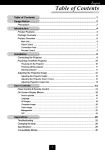
Selecting A Location The further your projector is from the screen or wall, the
larger the image. The minimum size the image can be is approximately 24"
(0.61 m) measured diagonally when the projector is roughly 4 feet (1.2 m)
from the wall or screen. The largest the image can be is 300" (7.6 m) when
the projector is about 40.35 feet (12.3 m) from the wall or screen.
Projection distance
Width
Height
Projection Distance and Image Size
Diagonal Image Size (inch)
2
300
300”
240
231”
200
160
120
100
80
60
40
20
0
0.0
WIDE
TELE
27”
24”
3.28
(1)
6.56
(2)
9.84 13.12 16.4
(3) (4) (5)
19.7
(6)
23.0
(7)
26.2
(8)
29.5
(9)
32.8
(10)
36.1
(11)
39.4 40.35 ft.
(12) (12.3) (m)
Projection Distance
Screen size
(diagonal)
INSTALLATION
30
31
Projection Distance
Wide
Screen size
inch
40”
60”
70”
80”
90”
100”
120”
150”
180”
200”
240”
270”
300”
Projection angle α
Degree
14.8
14.8
14.7
14.7
14.6
14.6
14.6
14.6
14.5
14.5
14.5
14.5
14.5
Screen width H
inch
32
48
56
64
72
80
96
120
144
160
192
216
240
mm
813
1219
1422
1626
1829
2032
2438
3048
3658
4064
4877
5486
6096
inch
65.2
97.8
114.8
131.6
148.3
164.8
198.5
248.7
298.9
332.3
399.2
449.4
500.2
mm
1655
2483
2915
3342
3767
4185
5042
6316
7591
8441
10140
11415
12704
inch
4.7
7.0
8.2
9.3
10.5
11.7
14.0
17.5
21.0
23.3
28.0
31.5
35.0
mm
119
178
207
237
267
296
356
444
533
593
711
800
889
inch
63
94.5
111
127.3
143.5
159.4
192.1
240.7
289.3
321.7
386.5
435.1
484.3
mm
1600
2400
2819
3233
3645
4049
4879
6114
7348
8171
9817
11052
12301
inch
12
18
21
24
27
30
36
45
54
60
72
81
90
mm
305
457
533
610
686
762
914
1143
1372
1524
1829
2057
2286
inch
24
36
42
48
54
60
72
90
108
120
144
162
180
mm
610
914
1067
1219
1372
1524
1829
2286
2743
3048
3658
4115
4572
Screen size
inch
40”
60”
70”
80”
90”
100”
120”
150”
180”
200”
240”
270”
300”
Projection angle α
Degree
11.4
11.4
11.4
11.4
11.3
11.3
11.3
11.3
11.3
11.3
11.2
11.2
–
Screen width H
inch
32
48
56
64
72
80
96
120
144
160
192
216
–
mm
813
1219
1422
1626
1829
2032
2438
3048
3658
4064
4877
5486
–
inch
84.4
126.5
147.2
168.7
190.8
212.8
255.2
319.6
384.0
426.3
512.7
577.2
–
mm
2143
3213
3739
4286
4847
5406
6483
8117
9753
10829
13024
14660
–
inch
4.7
7.0
8.2
9.3
10.5
11.7
14.0
17.5
21.0
23.3
28.0
31.5
–
mm
119
178
207
237
267
296
356
444
533
593
711
800
–
inch
82.7
124
144.3
165.4
187.1
208.7
250.3
313.4
376.6
418.1
502.9
566.1
–
mm
2101
3150
3665
4201
4752
5301
6358
7960
9566
10620
12774
14379
–
inch
12
18
21
24
27
30
36
45
54
60
72
81
–
mm
305
457
533
610
686
762
914
1143
1372
1524
1829
2057
–
inch
24
36
42
48
54
60
72
90
108
120
144
162
–
mm
610
914
1067
1219
1372
1524
1829
2286
2743
3048
3658
4115
–
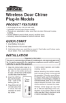
A
B
Projection distance C
D
E
Tele
A
B
Projection distance C
D
E
* For Screen Sizes of 24 to 300 inches not indicated on the projection tables, use the formulas on the next page.
INSTALLATION
32
33
Unit (inch)
H (inch) = Width of screen
A = C / cosα
B = 3.7H / 25.4
C (WIDE) = (2.0262H) – 2.437
C (TELE) = C (WIDE)21.3
D=E/2
E = H / 423
Desk top
Screen
C
Screen center
E
A
D
Screen bottom
α
B
3.8”
(96.64mm)
Projector base
Ceiling mount
C
3.8”
(96.64mm)
Projector base
α
B
Unit (mm)
H (inch) = Width of screen
A = C / cosα
B = 3.7H
C (WIDE) ={(2.0262H) – 2.437} 225.4
C (TELE) = C (WIDE)21.3
D=E/2
E = H / 423
A : Distance between lens center and
screen center
B : Vertical distance between lens center
and screen bottom (screen top for ceiling mount)
C : Horizontal throw distance between
screen surface and projector lens
D : Vertical distance between screen
center and screen bottom (screen top
for ceiling mount)
E : Screen Height
A
Screen top
D
E
Screen center
INSTALLATION
34
35
Using A Tabletop Or Cart
(A) Top view
screen
1. Place your projector on a flat level surface at the optimal distance
from the screen or wall so you realize the size image you want.
(Avoid having bright room lighting or sun light directly on the
screen or wall where you'll be projecting the image.)
2. Connect the power cable, remove the lens cap and turn the projector
on. (If no input signal is available, the projector will display a
background image.)
(B) Side view
3. Ensure that the projector is square to the screen.
4. Move the projector left or right to center the image horizontally on
the screen. (A)
screen
5. To center the image vertically (B), lift the front edge of the projector
and press the buttons on the front of the projector, just above the
feet, to release the one-touch tilt feet. (There is approximately 5.0˚
of up and down adjustment for the front of the projector.
6. To fine tune the image's position vertically on the screen, rotate each
front foot, and rear feet if necessory.
NOTE: Adjust feet so that lens surface is parallel to the screen.
If you use the projector with the screen tilted, the picture will be
distorted.
7. Adjust the size of the image using the zoom ring lever on the lens.
NOTE: The set up angle of the projector should not exceed 15
degrees, otherwise lamp life could decrease dramatically.
Up Down
Up
Down
Focus ring
Zoom ring lever
INSTALLATION
36
37
Transporting and storing the projector
A padded carrying case has been supplied with your projector.
Please use this case when transporting and storing the projector. The
carrying case also has a compartment for your laptop computer.
To use the carrying case follow the directions below:
3. Hold the projector by it’s handle and slide it into the large
compartment of the carrying case.
Projector
SELECT
ON / OFF
ENTER
POWER
STATUS
2. Zip up the sides of the case.
MEMU
AC IN
1. Unfold carrying case.
4. Zip up the top of the case.
Zipper
5. Unlatch the belt and then place your notebook computer into the
front pouch.
Note book PC
7. Store the remote control and other accessories in the side
pouches on the carrying case.
1
2
Other Accessories
When storing the remote
control, place the remote in
its protective case. The
case will keep the remote
buttons from being accidentally pushed while it is
being stored or transported. This will keep the
batteries from being discharged.
6. Latch the belt.
2
1
* Carry the projector carefully. Bumping or dropping the projector
may cause damage.
INSTALLATION
38
39
WARNING
•
•
•
•
Only use your projector on a solid, level surface. If the projector falls to the ground, you can be injured and the projector severely damaged.
Do not use the projector where temperatures vary greatly. The projector must be used at temperatures between 41˚F (5˚C) and 95˚F (35˚C).
Do not expose the projector to moisture, dust, or smoke. This will harm the screen image.
Ensure that you have adequate ventilation around your projector so
heat can dissipate. Do not cover the vents on the bottom or the side
of the projector.
100"–131"
19ft (5791.6mm)
NOTE : Distances may vary ± 5%.
200"–261"
2.27ft
(691.8mm)
1.2m (3.94ft)
15.7ft (4785.2mm)
Installing your MultiSync LT100 Projector on the ceiling must be done
by a qualified technician. Contact your NEC dealer for more information.
Do not attempt to install the projector yourself.
80"–104"
60"–78"
40"–53"
24"–31"
233"–303"
Ceiling Installation
2.1m (6.89ft)
3.15m (10.33t)
4.2m (13.78ft)
5.3m (17.39ft)
10.65m (34.94ft)
12.3m (40.35ft)
If your projector is mounted on the ceiling and your image is upside
down, use the “Menu” and “Select” buttons on your projector cabinet
or (▲) (▼) buttons on your remote control to correct the orientation.
(See page 68.)
Projection distance and screen size examples
• Horizontal projection position
Lens centered left to right
• Vertical projection position
Projection distance L ft.
Wide (W)
Tele (T)
3.94ft (1.20m)
5.25 ft (1.60m)
6.89ft (2.10m)
7.87 ft (2.40m)
10.33ft (3.15m)
10.66ft (3.25m) 13.78ft (4.20m)
13.3ft (4.05m)
17.39ft (5.30m)
26.9ft (8.20m)
34.94ft (10.65)
40.35ft (12.30m)
Dimension H inch
Both W & T
2.76” (7.0cm)
4.8” (12.2cm)
6.93” (17.6cm)
9.37” (23.8cm)
11.46” (29.1cm)
23.58” (59.9cm)
35.08” (89.1cm)
H
Screen size
Inches
24
40
60
80
100
200
300
L
INSTALLATION
40
41
Wiring Diagram
VIDEO INPUT
INTPUT
OUTPUT
REMOTE
CONTROL
PC CONTROL
S-VIDEO VIDEO L(MONO) -R-AUDIO
RGB INPUT
RGB OUTPUT
RGB
AUDIO
RGB
AUDIO
Document Camera
To video, S-video, and audio
inputs on the projector
VCR, Laser Disk Player or DVD Player
To RGB input on the projector
DVD Player with Y/Cb/Cr output
Signal cable (supplied)
To mini D-Sub 15-pin connector on the Projector
Pin adapter for Macintosh
(supplied)
IBM VGA or Compatibles
PS/2 mouse adapter
(supplied)
Macintosh or Compatibles (Desk top type)
Remote Mouse
Receiver
Mac ADB adapter
(supplied)
Remote Mouse
Receiver
Remote Control Guideline
1. Plug the serial cable with the remote mouse receiver into your computer's mouse port and restart your computer to gain remote mouse
control.
2. When using the remote control's built-in infrared mouse on a laptop computer, the laptop's mouse, trackball or trackpad will be disabled.
Disconnect the infrared receiver and restart your computer to regain trackball or trackpad mouse control.
3. If the screen goes blank while using your remote control, it may be the result of the computer's screen-saver or power management
software. If you accidentally hit the OFF button on the remote control, wait one full minute and then press the ON button to resume.
INSTALLATION
42
43
Connecting Your PC Or Macintosh Computer
Connecting your PC or Macintosh computer to your MultiSync LT100 (XGA) Projector will enable you to project your computer's screen image
for an impressive presentation. All of these following display standards are supported:
VGA 6402480 for graphics
VGA 6402400 for graphics
VGA 6402350 for graphics
VGA 7202400 for text
VGA 7202350 for text
SuperVGA 8002600
Macintosh at 6402480
Macintosh at 8322624
XGA10242768
Macintosh at 10242768
SXGA128021024 (AccuBlend)
To connect to a PC, Macintosh or computer equipped with an XGA/SVGA/VGA adapter or compatible graphics adapter, simply:
1. Turn off the power to your projector and computer.
2. If your PC does not support XGA/SVGA/VGA you will need to install an XGA/SVGA/VGA graphics board. Consult your computer's owner's
manual for your XGA/SVGA/VGA configuration. If you need to install a new board, see the manual that comes with your new graphics board for
installation instructions.
3. Use the signal cable that's supplied to connect your PC or Macintosh computer to the projector. For Macintosh, use the supplied pin adapter to
connect to your computer's video port.
4. Turn on the projector and the computer.
5. If the projector goes blank after a period of inactivity, it may be caused by a screen saver installed on the computer you've connected to the
projector.
When using a Macintosh with the LT100, set the DIP switch of the supplied pin adapter according to your resolution. After setting, restart your
Macintosh.
See the following pages for setting of the DIP switch.
• When using with a Macintosh, XGA (10242768) is recommended if your Macintosh supports this mode.
• When using with a Macintosh PowerBook, output may not be set to 8002600 unless “mirroring” is off on your PowerBook. Refer to owner’s manual
supplied with your Macintosh computer for mirroring.
NOTE: A Video Adapter cable manufactured by Apple Computer is needed for a PowerBook which does not have a mini D-Sub 15-pin connector.
Settings for Macintosh adapter
Macintosh models applied
Setting Mode (Fixed resolution)
Setting required to be selected resolution on Mac after
restarting.
Desktop type and PowerBook with 8002600
LCD panel
16” fixed mode (output is 8322624)
Set to VGA/SVGA (8002600)
PowerBook with 6402480 LCD panel
13” fixed mode (output is 6402480)
Set to 17” multi-scan mode (6402480)
Desktop type with AccuBlend
19” fixed mode (output is 10242768)
Set to 17” multi-scan mode (10242768)
INSTALLATION
44
45
Settings for Monitor Mode
Number of DIP switch
S1
S2
S3
S4
S5
S6
S7
S8
Monitor size
ON
15” multi-scan mode /16”–13”
17” multi-scan mode /19”–13”
ON
ON
ON
19” multi-scan mode /21”–13”
13” fixed mode /6402480
ON
ON
ON
ON
VGA/SVGA mode
16” fixed mode /8322624
ON
ON
19” fixed mode /10242768
NOTE: For setting other than display modes supported by your Macintosh and LT100, using of the DIP
switch may bounce a image slightly or may display nothing. If this happens, set the DIP switch to the 13”
fixed mode and then restart your Macintosh. After that, restore to a displayable mode and then restart the
Macintosh again.
Make sure that LT100 and your Macintosh are connected with the pin adapter and the supplied signal
cable (mini D-Sub 15-pin connector) and then restart your Macintosh.
Examples of DIP switch setting
VGA/SVGA mode
17” multi-scan mode
1 2 3 4 5 6 7 8
→
ON
→
ON
→
ON
19” fixed mode
1 2 3 4 5 6 7 8
1 2 3 4 5 6 7 8
NOTE: Refer to your computer's owner's manual for more information about your computer's video
output requirements and any special identification or configuring your projector's image and monitor
may require.
INSTALLATION
46
47
Changing Video Resolutions
Depending on your computer's graphic capability, you may be able
to select one of several resolutions. Generally a computer- either a
PC or Macintosh- with 1 meg. of memory will run:
6402480 at 16.7 million colors (24 bit Truecolor)
8002600 at 65 thousand colors.
10242768 at 256 colors.
As the resolution increases, the number of colors you can run decreases. With 2 meg. of memory a computer will run:
6402480 at 16.7 million colors (24 bit Truecolor).
8002600 at 16.7 million colors (24 bit Truecolor).
10242768 at 65 thousand colors.
128021024 at 256 colors.
Windows 95
There are two methods you can use to change your resolution.
Method 1
1. Move your cursor to the background image and click.
2. In the "Properties" menu, select "Settings."
3. Change your resolution and click "OK."
4. You may be asked to reboot for the changes to take effect, or you' ll
get a message that "Windows is about to resize your display." When
asked if you want to keep your settings, select "Yes."
Method 2
1. Click on your "My Computer" icon.
2. Open "Control Panel" and select "Display."
3. Change your resolution and click "OK." after the new resolution is
selected.
4. You may be asked to reboot for the changes to take effect, or you' ll
get a message that "Windows is about to resize your display." When
asked if you want to keep your settings, select "Yes."
Windows 3.1
1. Click on the "Main" icon and open "Control Panel."
2. Select "Change System Settings" and click on "Option."
3. Choose "Change Display Settings."
4. Select the resolution you want.
5. Choose the current drive or another.
6. Restart Windows for the changes to take effect.
Macintosh
1. Under the Apple menu, select "Control Panels" and open "Monitors."
2. Click and open "Options."
3. Select your new resolution and click "OK."
If you have an NEC monitor connected to your Macintosh, you may
have a "DPI-On-The-Fly" extension that enables you to change your
resolution directly. The "DPI-On-The-Fly" icon is under your Apple
menu.
INSTALLATION
48
49
Connecting Your DVD Player
You can connect your MultiSync LT100 Projector to a DVD player with the component outputs or Video output. To do so, simply:
1. Turn off the power to your projector and DVD player.
2. If your DVD player has the component video (Y,Cb,Cr) output use the optional 15-pin-to-RCA23 cable to connect your DVD player to the
RGB INPUT connector on the LT100.
For a DVD player without component video (Y,Cb,Cr) outputs, use common RCA cables (not provided) to connect a composite VIDEO
output of the DVD player to the Video Input of the LT100.
3. Turn on the projector and the DVD player.
NOTE: Refer to your DVD player's owner's manual for more information about your DVD player's video output requirements.
Connecting Your Document Camera
You can connect your MultiSync LT100 Projector to a document camera. To do so, simply:
1. Turn off the power to your projector and document camera.
2. Use a standard video cable to connect your document camera to the Video input on your projector.
3. Turn on the projector and the document camera.
NOTE: Refer to your document camera's owner's manual for more information about your camera's video output requirements .
Connecting Your VCR Or Laser Disc Player
Use common RCA cables (not provided) to connect your VCR or laser disc player to your MultiSync LT100 Projector. To make these connections,
simply:
1. Turn off the power to your projector and VCR or laser disc player.
2. Connect one end of your RCA cable to the video output connector on the back of your VCR, or laser disc player, connect the other end to the
Video input on your projector. Use standard RCA audio patch cords to connect the audio from your VCR, or laser disc player to your projector
(if your VCR, or laser disc player has this capability). Be careful to keep your right and left channel connections correct for stereo sound.
3. Turn on the projector and the VCR, or laser disc player.
NOTE: Refer to your VCR, or laser disc player owner's manual for more information about your equipment's video output requirements.
Connecting An External Monitor
You can connect a separate, external monitor to your projector to simultaneously view on a monitor the image you're projecting. To do so:
1. Turn off the power to your projector and computer, document camera or video source.
2. Use a 15-pin cable to connect your monitor to the RGB OUTPUT connector on your LT100 projector.
3. Turn on the projector and the computer, document camera or video source.
INSTALLATION
50
51
Connecting Your Remote Mouse Receiver
The remote mouse receiver enables you to operate your computer's mouse functions from the NEC MultiSync LT100
remote control. It is a great convenience for clicking through your computer-generated presentations.
To connect the remote mouse receiver:
1. Turn off your computer.
2. For PCs: Remove your current mouse and connect the serial cable from the remote mouse receiver to your PC's
mouse port. (Use the 6-pin adapter for connecting to a PS/2 computer.)
For Macintosh: Remove your current mouse from your computer, attach the Macintosh adapter to the remote
mouse receiver's serial cable, and connect the receiver to your mouse port.
3. When the remote mouse receiver is installed, it will disable your regular mouse, disconnect the remote mouse
receiver and restart your computer.
Input for wired remote control
IBM PC/AT
Input for wired remote control
Macintosh
IBM PS/2
INSTALLATION
52
53
m The Remote Mouse Receiver as a mouse for your computer
Serial cable (supplied)
m The Remote sensors on the projector cabinet work as
the remote sensor on the Remote Mouse Receiver
Remote cable
(supplied)
Serial cable
(supplied)
Remote Control
Output
Insert the supplied remote cable here.
m You can daisy-chain as many as five projectors and operate them with the same remote control.
To do so:
1. Turn off your computer.
2. Use the remote control cables supplied to connect the Remote Control Output of one
projector to the Remote Control Input of the next until all the projectors are connected.
Remote cable (supplied)
INTPUT
OUTPUT
S-VIDEO
RGB INPUT
REMOTE
CONTROL
RGB
INSTALLATION
54
3
O P E R A T I O N
55
This section describes how to select a computer or video source and how to adjust the
picture and sound.
General Controls Before you turn on your MultiSync LT100 Projector, ensure that
the computer or video source is turned on and that your lens cap is removed.
1. Turn On The Projector The main power switch is on the back panel of the
MultiSync LT100 Projector. By turning this switch on, the projector will go into its
standby mode and the power light will glow amber. Only after you press the "On"
button on the remote control or projector cabinet will the power light turn to green
and the projector become ready to use.
NOTE: To turn the projector on and off with just the back panel switch, use the menu
and enable the "auto start" feature. (See page 65. )
2. Select The Computer Or Video Source Press the "Video" (VCR, DVD player,
document camera, or laser disc player), "S-video", "RGB" (computer), or "PC
Card" button on the remote control to display the image. Or press the "Menu"
button on the cabinet and use the icons to select your video source: "Video", "SVideo", "RGB" or "PC Card".
3. Adjust The Image Size Adjust the size of the screen with the zoom ring lever on the
projector.
4. Focus Adjust the focus with the focus ring on the projector.
5. Turning Off The Projector First press the "off" button on the remote control or press
and hold down the "on/off" button on the cabinet for one second. The power light will
glow amber. Then turn off the main power switch on the back panel. The power light
will go out.
IMPORTANT:
•
•
The projector should be unplugged if it will not to be used for an extended period.
To turn off the image briefly (five minutes or less), use the "Picture Mute" button
instead of turning the projector off and on.
• The projector will display a black, blue image or focus pattern if no input signal is
present.
• Do not turn the projector off and then immediately back on. The projector needs to
cool for a minute before it can be restarted.
OPERATION
56
57
Using The Menus
1. Press the "Menu" button on the remote control or projector cabinet to display the Main Menu.
2. Press the "Select" button on the projector cabinet or (▲) (▼) buttons on your remote control to highlight the menu for the item you want
to adjust.
3. Press the "Enter" button on the projector cabinet or the "Left Click" button on the remote control to select a submenu or item.
4. Adjust the level or turn the selected item "on" or "off" by using the "Adjust" (+) or (–) buttons on the remote control or cabinet. The on-screen
gauge will display your changes. The (+) button is "on" and (–) is "off".
5. The change is stored until you adjust it again.
6. Repeat steps 2-5 to adjust an additional item, or press “Right-Click” on your remote control to quit the menu display.
VIDEO/ S-VIDEO
RGB
YCbCr
NOTE: The following explains conditions that you will encounter when operating your LT100 while displaying an SXGA
(128021024) image.
When a menu or message is displayed while an SXGA image is
projected, several lines of information will be lost.
When the "LAMP USAGE 1000 HOURS" message appears, several lines of information will be lost.
The "LAMP USAGE 1000 HOURS" message will not appear
when the freeze button is activated.
SXGA images inherently display a 5 to 4 ratio, resulting in an
image that appears to be smaller and more square than the 4 to
3 format commonly displayed.
OPERATION
58
59
Menu Descriptions & Functions
Source Menu
Enables you to select a video source such as a VCR, DVD player, laser disk player, computer or document camera depending on what is connected to your inputs. Press the "Select"
button on the projector cabinet or (▲) (▼) buttons on your remote control to highlight the
menu for the item you want to adjust.
Video
Selects device connected to your video input (VCR, document camera, laser disk player or
DVD player).
S-Video
Selects device connected to S-Video input (Laser disk player, S-VHS VCR or DVD player).
RGB
Selects computer connected to your RGB input. Use the "Adjust" (+) or (–) buttons to
select a standard* or one of five custom settings you can create and store. Press the "Enter"
button on the cabinet or the "Left Click" button on the remote control to save your selection.
NOTE: If a previously saved custom memory location is used with a new or different input signal
it may not sync up, producing a distorted image, or no image at all. If so, follow the instructions
below:
1) Disconnect the signal cable so that there is no input signal. In this condition the on-screen
message will be displayed.
2) Select RGB standard from the source menu.
3) Connect the signal cable again.
NOTE: * Standard is normally used and it can be user changed and automatically recalled.
PC CARD
This feature enables you to make a presentation using the Viewer function with the optional
LT Viewer board (VK-LT) installed.
Press the Mouse pad (+) or (-) buttons to select "START" for the image you want to display
first and "SELECT FILE" for the file you want to select or "Select Slide" for the image you
want to slide.
OPERATION
60
61
Image Adjustment Menu
Provides access to controls for your image and sound. Use the “Select” button on the projector cabinet or (▲)
(▼) buttons on your remote control to highlight the menu for the item you want to adjust.
The volume, image mode, brightness, contrast, color, tint, sharpness and white balance controls are available for
Video or S-Video sources.
The volume, image mode, brightness, contrast, horizontal position, vertical position, white balance, alignment
and auto picture controls are available for RGB source.
Volume
Use the “Adjust” (+) or (–) buttons to adjust the volume.
Image Mode
Use the "Select" button on the projector cabinet or (▲) (▼) buttons on your remote control to select the item you
want to adjust.
NOTE: Input and Display modes are not available for PC CARD.
Gamma ............. Use the mouse pad (+) or (–) buttons to choose "Normal" when in a lighted room and "Natural
1&2" when in a darkened room. "Natural 1" for better flesh tone; "Natural 2" for true reproduction of middle tones.
Input Mode ....... Use the mouse pad (+) or (–) buttons to choose "DOC CAM" for a document camera or other
low APL input, "Standard Video" for a regular video picture such as NTSC, "RGB Signal" for
an RGB source such as a computer, or "Y/Cb/Cr Signal" for a component video source such as
a DVD player.
Display Mode ... Use the mouse pad (+) or (–) buttons to choose "Normal Aspect" for normal video picture with
a 4-to-3 aspect ratio and "Wide Aspect" for DVD's with a 16-to-9 aspect ratio.
NOTE:
1) Flicker may appear on a freeze-frame picture with a Video or S-Video source. If this happens, select the
Document Camera mode using the Image mode icon on the Image Adjustment Menu, and then adjust the
contrast and other items for an optimal image.
2) A frame may freeze for a brief period of time when a video is played back in fast-forward or fast-rewind with
a Video or S-Video source. If this happens, select the Natural mode (for cinema) using the Image Mode icon
on the Image Adjustment Menu.
OPERATION
62
63
Brightness
Use the “Adjust” (+) or (–) buttons to adjust the brightness.
Contrast
Use the “Adjust” (+) or (–) buttons to adjust the contrast.
Color*
Use the “Adjust” (+) or (–) buttons to adjust the color.
Tint*
Use the “Adjust” (+) or (–) buttons to adjust the tint.
Sharpness*
Use the “Adjust” (+) or (–) buttons to adjust the sharpness.
White Balance
Use the Mouse pad (+) or (–) buttons to adjust the white balance.
For Video/RGB ... Brightness for each color (RGB) is used to adjust the black level of the screen; Contrast for each
color (RGB) to adjust the white level of the screen.
For Y/Cb/Cr ........ Brightness for each color (Y/Cb/Cr) is used to adjust the white level of the screen; Contrast for
each color (Y/Cb/Cr) to adjust the black level of the screen.
Alignment
Use the Mouse pad (+) or (–) buttons to adjust the horizontal and vertical position, "Picture", and "Fine Picture".
Horizontal
Position.. ........ Use the “Adjust” (+) button to move the image right; (–) to move it left.
Vertical
Position.. ........ Use the “Adjust” (+) button to move the image up; (–) to move it down.
Auto Picture..
Use the “Adjust” (+) button to turn this feature on so “Picture” and “Fine Picture” adjustments are made automatically. Use the “Adjust” (–) button to turn this feature off so you can make “Picture and Fine Picture” adjustments
manually.
RGB AUTO PICTURE ON
RGB AUTO PICTURE OFF
Picture Adjustment ..(when AUTO PICTURE is off)
Use this icon with the “Fine Picture Adjustment” to fine tune the computer image or to remove any vertical banding that might
appear. This function adjusts the clock frequencies to eliminate the vertical banding in the image. Press the “Adjust” (+) and (–)
buttons until the banding disappears. This adjustment may be necessary when you connect your computer for the first time. This
adjustment is made automatically when the Auto Picture is turned on.
Fine Picture ..(when AUTO PICTURE is off)
Use this icon to adjust the clock phase or to reduce video noise, dot interference or cross talk. (This is evident when
part of your image appears to be shimmering.) Use the “Adjust” (+) and (–) buttons to adjust the image. Use the Fine
Adjustment only after the Picture Adjustment is complete. This adjustment is made automatically when the Auto
Picture is turned on.
NOTE:
, Color, Tint, and Sharpness controls will not work with an RGB source. The Tint control will not work with a PAL
or SECAM source. The Color and Tint controls will work with a Y/Cb/Cr source.
,, Alignment controls such as Horizontal and Vertical position controls, and Picture, Fine Picture and Auto Picture
adjustments will not work with a Video or S-Video source.
OPERATION
64
65
Power Menu
Provides access to Lamp Usage information, the Auto Start, Power Management and Onscreen Mute features. Use the “Select” button on the projector cabinet or (▲) (▼) buttons on
your remote control to access a submenu. Then press “Adjust” (+) or (–) to choose a specific
option.
Lamp Usage
This tells you how long the lamp has been in operation. It is recommended that you replace a
lamp after 1000 hours of service. After you install a new lamp, select this icon and press and
hold the “Power On” button on the remote control for ten seconds to reset the lamp clock back
to zero.
NOTE: The projector will turn off and go into stand by mode after 1100 hours of service. If this
happens, press the "Power Off" button on the remote control for ten seconds to reset the lamp clock
back to zero. Do this only after replacing the lamp.
Auto Start
Turns the projector on automatically when the main power switch is turned on. This eliminates the need to always use the “Power” button on the remote control or projector cabinet.
Press (+) to turn this feature on and (–) to turn it off.
Power Management
When “Power Off” is on and there is no video input for five minutes or more, the projector
will automatically turn itself off. Press the (+) to turn this feature on and (–) to turn it off.
On Screen Mute
Use the mouse pad (+) button to turn off the On Screen Mute ; (–) to restore it.
The On screen Mute feature keeps the menu from displaying when the projector is turned
on or when switching inputs.
OPERATION
66
67
Settings Menu
Enables you to set preferences and other operating options. Use the “Select” button on the projector cabinet or
(▲) (▼) buttons on your remote control to access the submenu you want.
Custom Memory
This enables you to save your current settings for an RGB source in one of five memories, Custom 1-5.
To change the STANDARD settings, proceed as follows:
1. Connect your computer to the MultSync LT100.
2. Select the "STANDARD" in RGB source.
3. Adjust the horizontal/vertical position, Picture, and Fine Picture adjustments.
4. Select the Custom Memory icon.
5. Press the "Adjust" (+) or (–) buttons to choose a memory location, then press "Enter" on the cabinet or the "Left
Click" on your remote control to save the new settings.
If you do not want to change the STANDARD settings, first selct the Custom Memory icon, then do the same as
step 5.
Capture (with the optional viewer board installed only)
When the Capture is selected, press "Enter" on the projector cabinet or Left Click button on the remote control
to display "Execute" and "capture" an image from a source that is currently being displayed.
When capturing is completed, "Completed" is displayed under the Capture icon.
Unless a flash memory card is inserted into the slot of the viewer board, "No Card" is displayed. This means that
the Capture feature is not available. The "Card Error" display means that the free space of the flash memory card
is insufficient for saving images. Make more space available on the card by erasing unwanted images with your
PC. The number of images that can be captured depends on the size of the flash memory card.
NOTE: Be sure not to turn off the power or remove the flash memory card unless "Completed" is displayed. Doing so
could cause a loss of the data in the flash memory card or damage to the card itself.
Background
Use this feature to display a black, blue screen or focus pattern when no signal is available. Press the mouse pad (+) or (-) buttons to
choose the back screen you want. Press "Enter" on the cabinet or the "Left Click" on your remote control to save your change.
Projection
This reorients your image based upon projector location. Press the “Adjust” (+) or (–) button until it is correct.
Press “Enter” on the cabinet or the “Left Click” on your remote control to save your change. The options are:
front floor projection, rear ceiling projection, rear floor projection, and front ceiling projection.
Language
Use the “Adjust” (+) or (–) to choose one of six languages for on-screen instructions. Press “Enter” on the cabinet or the
“Left Click” on your remote control to save your change. The options are: English, German, French, Italian, Spanish and
Swedish.
Reset
Changes all adjustments to the factory preset levels for each source individually. To activate, you must hold down the “Adjust”
(+) button on the cabinet or remote control for at least two seconds. The adjustments that will be reset are horizontal and vertical
control, picture and fine picture adjustment (for the current source only), brightness, contrast, color, tint, and sharpness.
When custom setting is selected, reset changes all adjustments to the factory preset levels of the current input signal for
selected custom memory location. This will not return to your previous custom setting and will delete your saved settings
from custom memory.
OPERATION
68
69
Using the Viewer function
If you use the Viewer function on the projector, you must first install
the optional LT Viewer board (VK-LT) in the projector and set up the
exclusive software included with the VK-LT kit.
See the user's manual included with the VK-LT for installing and
uninstalling the software.
Mounting the Optional LT Viewer Board
To install the Viewer board:
1. Switch off the main power and unplug the power cord. Turn the
projector so that the bottom is up.
3. Place the board in place and secure it with the four screws supplied
with the VK-LT board.
OPERATION
2. Remove the screw from the board cover.
4. Attach the two foot caps to adjust projector height. After completing, put the projector back in the original position.
70
71
To Project the Slides (the presentation materials)
1. Insert a flash memory card into the PC card slot.
* To eject the flash memory card, press the Eject button.
NOTE: Should the card be difficult to insert, do not forcefully
push the card in.
2. Select the PC card as a source.
* Press the Menu button on the remote control or projector cabinet and select "PC CARD" from the Source menu.
P
Fla CMC
sh IA
Me -A
mo TA
ry C
ard
Projecting Slides
Orientation of flash memory card insertion
The flash memory card has a front and a back side and the flash
memory card is designed to be inserted in only one orientation. The
card is designed so that it cannot be inserted in reverse. Trying to
force the card into slot may result in damage to the card and the
PCMCIA card slot. See the flash memory card manual for information about the orientation of the flash memory card.
* If there is no flash memory card in the card slot, the projector
displays a blue back or black back image.
* The type of flash memory card required for use in the projector is
a Type II PCMCIA-ATA flash memory card. Never use a different
type of card, doing so may result in damage to the card or PC card
slot.
4. Select a file or a slide.
Use the mouse pad (+) or (–) button on the remote control to
select the file or slide you want to display and press the Enter
button on the cabinet or the Left Click button on the remote control. See the following pages for more details.
3. Select "Select File" or "Select Slide".
* Use the mouse pad (+) or (-) button on the remote control to
select "Select File" or "Select Slide".
NOTE: The mouse pad (+) or (–) button is valid only when the
Menu button is lit.
Multi Cursor
Table Cursor
1
5
File
File
2
6
File
File
3
7
File
File
4
A
8
E
File
presentation presentation presentation presentation
File
B
F
C
G
D
H
presentation presentation presentation presentation
* The selected file or slide will be displayed.
NOTE: If you select "Start" and press the Enter button on the
cabinet or the Left Click button on the remote control, the slides
will be looped. To use the Start feature, you must first set on the
software included with the LT Viewer board.
OPERATION
72
73
Selecting a File from a List of Files
* The Viewer feature allows you to store one or more presentation
materials in a single flash memory card. Each material is referred to
as a "file" or "slide".
To select a file from a list of files
1. Press the Menu button on the remote control or cabinet to select
"PC Card".
3. Use the mouse pad (+) or (–) button on the remote control to
move the Multi-Cursor (blue box) to the file you want to display a slide from, and press the Enter button on the cabinet or
the Left Click button on the remote control.
Multi Cursor
1
5
File
File
2
6
File
File
3
7
File
File
4
8
File
File
2. Use the mouse pad (+) or (-) button on the remote control to select "Select File" and press the "Enter" button on the cabinet or
the Left Click button on the remote control.
* This will display the first slide of the selected file.
NOTE: A maximum of 16 indexes can be switched with "Select
File". The last displayed file, which is always exclusively for use
of Capture, will be displayed during capturing only.
When 17 or more indexes exist n the flash memory card and you
wish to display them, move the index to be displayed to the beginning of the file indexes with "Editing file indexes" under "Files"
of the software for Viewer.
3. Use the mouse pad (+) or (–) button on the remote control to
move the Table-Cursor (yellow box) to the slide you want to
display and press the Enter button on the cabinet or the Left
Click button on the remote control.
Table Cursor
A
E
B
F
C
G
D
H
presentation presentation presentation presentation
Selecting a Slide from a List of Slides (Table)
To select a slide from a list of slides
1. Press the Menu button on the remote control or cabinet to select
"PC Card".
2. Use the mouse pad (+) or (-) button on the remote control to select
"Select Slide" and press the "Enter" button on the cabinet or the
Left Click button on the remote control.
OPERATION
presentation presentation presentation presentation
* This will display the selected slide.
NOTE: The Slide (+) and (–) button on the remote control
can be also used to select a file or slide, or to turn pages.
74
75
Switching Slides
To switch slides, press "SLIDE +" or "SLIDE –" button. This will
cancel the Auto Play mode. To set the Auto Play mode, press the Menu
button to select “Start” from the Source menu and press the Enter
button on the cabinet or the Left Click button on the remote control.
This is valid only when the Auto Play mode is selected. See more
information about “Auto Play mode” for the Help file included with the
Viewer board.
* SLIDE– returns to the previous slide.
SLIDE+ advances to the next slide.
NOTE: Editing tasks such as deleting the data inside the flash memory
card cannot be accomplished with the projector. Use the exclusive software on your PC for this purpose. If you accidentally delete data required for playback, playing back the data is not possible.
Capturing the displayed image
The Viewer feature allows you to capture a screen image and store
it to a flash memory card.
To capture a screen image and store it to a flash memory card;
Select "Capture" from the Settings menu and press the Enter button
on the cabinet or Left Click button on the remote control.
* To view the captured image
1. Select "Select File" from the Source menu and display a list
of files.
* A thumbnail (reduced image) of the first captured image
will be displayed.
Effect Sound
The Viewer function allows you to play back effect sound for the slide.
Playing back effect sound can be accomplished during the switching
slides or files only. To use this feature, you must first specify the effect
sound with the supplied software.
You can adjust volume by using the Volume button.
2. Use the mouse pad (+) button to move the Multi-Cursor (blue
box) to the last file and press the Enter button on the cabinet or
the Left Click button on the remote control.
Multi Cursor
1
5
File
File
2
6
File
File
3
7
File
File
4
8
File
Display Digital Images
Displaying a picture from the projector is possible if the picture
meets one of the following requirements:
* The picture is stored on an MS-DOS formatted ATA flash
memory card.
* The picture is stored as a compatible format.
File
The on-board Viewer searches the PC Card directory for a JPEG or
BMP formatted images.
* This will display the image you captured first.
NOTE: The menu indicating that capturing is now performing
will be displayed during capturing. During this time do not remove the flash memory card nor turn off the power of the projector. Doing so may destroy the data of the flash memory card.
* When the flash memory card becomes full, replace it with a new
card.
OPERATION
NOTE:
* Up to 128 images can be recognized as slides for one directory.
* To use special effects, read images from a flash memory card
and edit them using the supplied software, then store them to
another flash memory card.
76
4
M A I N T E N A N C E
77
This section describes the simple maintenance procedures you should follow
to replace the lamp and replace the batteries in the remote control.
Replacing The Lamp
After your lamp has been operating for 1000 hours or longer, the “status” light in the cabinet will turn red. Even though the lamp may still be
working, replace it at 1000 hours to maintain optimal projector performance.
Step 3
CAUTION
• DO NOT TOUCH THE LAMP immediately after it has been used. It will
be extremely hot. Allow at least one hour for the lamp to cool before
handling.
• DO NOT REMOVE ANY SCREWS except the lamp cover set screw
and two lamp case screws. You could receive an electric shock.
• Turn off the main power to the projector and disconnect the power cord.
Allow at least one hour for the lamp to cool.
• The projector will turn off and go into stand by mode after 1100 hours of
service. If this happens, be sure to replace the lamp. If you continue to
use the lamp after 1000 hours of use, the lamp bulb may shatter, and
pieces of glass may be scattered in the lamp case. Do not touch them as
the pieces of glass may cause injury. If this happens, contact your NEC
dealer for lamp replacement.
Lamp cover
Step 4
Lamp housing
Step 5
Lamp replacement procedure
1. Switch off the main power and unplug the power cord.
2. Turn the main unit so that the bottom is up.
3. Loosen the lamp cover retaining screw.
4. Slide the lamp cover in the direction of the arrow and remove it.
Step 6
CAUTION: Do not use a lamp other than the NEC replacement lamp.
Order this from your NEC dealer using your projector's model number.
5. Loosen the three retaining screws for the lamp housing.
(There is an interlock on the lamp housing to prevent the risk of electrical shock. Do not attempt to circumvent this interlock.)
6. Holding the handle, pull the lamp housing forward and take it off.
7. Install the new lamp housing and fasten with the three screws.
8. Fasten the three screws for the lamp housing.
9. Install the lamp cover back in its original position and fasten with the
retaining screw.
10. Reset the lamp time.
Select the lamp usage time menu, then press the ON button on the remote controller and hold it down for at least ten seconds.
NOTE: If resetting the lamp clock back to zero after 1100 hours of
service, press the "Power Off" (not "Power On") button on the remote
control for ten seconds. Do this only after replacing the lamp.
Step 7,8
Step 9
MAINTENANCE
78
79
Remote Control Battery Installation
1. Press firmly and slide the battery cover off.
2. Remove both old batteries and install new ones (AA). Ensure that you have the batteries' polarity
(+/–) aligned correctly.
3. Slip the cover back over the batteries until it snaps into place.
Operating Range
Range of 360˚ and a distance of 23 feet (7 m) from the remote sensor.
30˚
30˚
Operation distance
of 23 feet (7m)
MAINTENANCE
80
81
Cette section décrit les procédures simples d’entretien que vous aurez à
suivre pour remplacer la lampe et remplacer les piles de la télécommande.
Remplacement de la lampe
Lorsque la lampe a été utilisée pendant 1000 heures ou plus, le voyant “Status” (état) du
coffret s’allume. Même si la lampe peut encore fonctionner, remplacez-la au bout de
1000 heures pour conserver une performance optimale de votre projecteur.
PRECAUTIO N
• NE TOUCHEZ PAS A LA LAMPE juste après qu’elle a été utilisée. Elle est très
chaude. Laissez-la refoidir pendant au moins une heure avant de la manipuler.
• NE RETIREZ AUCUNE VIS mis à part la vis qui fixe le couvercle de lampe
et les deux vis du compartiment de lampe. Vous risquez de recevoir une
décharge éléctrique.
• Mettez le projecteur hors circuit et débranchez le cordon d’alimentation.
Laissez refroidir la lampe pendant au moins une heure.
• Le projecteur s’éteindra et restera en attente après 1100 heures d’utilisation.
Dans ce cas, remplacez la lampe. Si vous continuez d’utiliser la lampe après
1000 heures d’utilisation, l’ampoule peut se briser et des brisures de verre
peuvent être éparpillées dans le compartiment de la lampe. Ne les touchez pas
car elles peuvent vous blesser. Dans ce cas, contactez votre revendeur NEC
afin de procéder au remplacement de la lampe.
Etape 3
Couvercle de
la lampe
Etape 4
Boîtier de
lampe
Etape 5
Pour remplacer la lampe :
1. Mettre l'appareil sous tension et débrancher le cordon d'alimentation.
2. Retourner l'unité principale pour avoir accès à la partie inférieure.
3. Desserrer le vis de fixation du couvercle de la lampe.
4. Faire glisser le couvercle de la lampe dans la direction de la flèche et le déposer.
Etape 6
ATTENTION : ne pas utiliser une autre lampe que la lampe de remplacement NEC.
Commander celle-ci auprès du détaillant NEC à l'aide du numéro de modèle du projecteur.
5. Desserrer les trois vis du boîtier de lampe.
(Il y a un mécanisme de déclenchement dans le boîtier de lampe pour empêcher une
décharge électrique. Ne pas essayer de circonvenir ce mécanisme)
6. En maintenant la poignée, tirer le boîtier de lampe vers l'avant et l'extraire.
7. Installer le nouveau boîtier de lampe et le fixer avec les trois vis.
8. Serrer les trois vis du boîtier de lampe.
9. Réinstaller le couvercle de la lampe dans sa position d'origine et le fixer avec les vis de fixation.
10. Initialiser le temps de la lampe.
Sélectionner le menu de temps d'utilisation de la lampe, puis appuyer sur la touche
ON sur la télécommande et la maintenir enfoncée pendant au moins dix secondes.
REMARQUE : Pour remettre à zéro l’horloge de lampe après 1100 heures d’utilisation,
appuyez sur la touche “Power Off” (alimentation désactivée)(et non “Power On”
(alimentation activée)) de la télécommande pendant dix secondes. Effectuez cette
opération uniquement lorsque vous avez remplacé la lampe.
MAINTENANCE
Etape 7,8
Etape 9
82
83
Installation des piles de la télécommande
1. Appuyez fermement et retirez le couvercle des piles en le faisant glisser.
2. Retirez les deux piles usagées et installez de nouvelles piles (AA). Assurez-vous de respecter la
polarité (+/–) des piles.
3. Remettez le couvercle des piles en le faisant glisser, jusqu’à ce qu’il s’emboîte.
Portée de fonctionnement
Portée de 360 degrés et d'une distance de 7 mètres du capteur le télécommande.
30˚
Operation distance of 7m
30˚
MAINTENANCE
84
5
T R O U B L E S H O O T I N G
85
This section helps you resolve problems you may encounter while setting up or using your MultiSync LT100 Projector.
Status Light Messages
Condition
Status
OFF
m Normal
On Continually
m The projector lamp has exceeded 1000 hours of operation and should be replaced.
Blinking very rapidly
(On and off in a cycle of 1 sec.)
m The lamp housing is not correctly installed. Install it correctly.
Blinking rapidly
(On and off in a cycle of 4 sec.)
•
•
The temperature protector has been triggered. If the room temperature is high, move the projector
to a cooler location. If the temperature inside the projector is high, check the cooling fan ventilation hole and the ventilation hole on the bottom of the projector. If any of the holes are blocked,
remove whatever is blocking them.
The temperature protector has been triggered. If you switch the main Power switch Off, then
immediately switch it On again, sometimes the power does not come on. If this happens, wait one
minute, then switch the power On again.
Blinking Slowly
(On and off in a cycle of 8 sec.)
m The cooling fan has stopped. Contact your NEC dealer for service.
Blinking very slowly
(On and off in a cycle of 12 sec.)
m The lamp is not turned on.
• The projector was turned off and back on too quickly. Turn off the projector, wait one
minute, then turn the projector back on. Or the lamp is burnt out.
TROUBLE SHOOTING
86
87
Common Problems & Solutions
Problem
Check These Items
Does not turn on
• Check that the power cable is plugged in and that the power switch on the back panel is on.
• Ensure that the lamp cover and lamp housing are installed correctly. (See page 77.)
• Check the status light to see if the projector has overheated or the lamp usage exceeds 1100
hours.
No picture
•
•
•
•
•
•
Image isn’t square
to the screen
• Reposition the projector to improve its angle to the screen.
Picture is blurred
• Adjust the focus. (See page 36.)
• Reposition the projector to improve its angle to the screen.
• Ensure that the distance between the projector and screen is within the adjustment range of the lens.
Problem
Check These Items
Image is scrolling
vertically, horizontally
or both
• Use icons to select the source you want to input.
• If PC signal is set up in Custom Setting, select corresponding Custom Setting (Custom 1,
Custom 2, etc.).
Remote control does
not work
• Install new batteries. (See page 79.)
• Make sure there are no obstacles between you and the projector.
• Stand within 23 feet (7m) of the projector.
Status indicator is lit or
blinking
See the Status Light message chart on pages 85 and 86.
Cross color in RGB
mode
If “Auto Picture” is off, turn it on. If “Auto Picture” is on, turn it off and balance the image with the
Picture Adjustment icon and Fine Picture Adjustment icon.
Use the menu icons to select your source (Video, S-Video, RGB or PC Card). (See pages 59 and 60.)
Ensure your cables are connected properly.
Use icons to adjust the brightness and contrast.
Remove the lens cap.
Is the POWER indicator blinking?
Reset the settings or adjustments to factory preset levels using the RESET icon on the Settings
Menu.
To Contact Your NEC Service Representative, Call 1-800-836-0655
TROUBLE SHOOTING
88
6
S P E C I F I C A T I O N S
89
This section provides technical information about the MultiSync LT100 Projector's performance.
Optical
DMDTM
Single Chip Digital Micromirror Device(DMDTM), 10242768 dots
Lens
Manual zoom, manual focus
F 2.44 f =26-30 mm
Lamp
Metal halide lamp 280 W
Image Size
610-7620 mm (24-300 inches) diagonal
Projection Distance
1.2 – 12.3m
Contrast Ratio
Greater than 200 : 1
Color Temperature
7000 Kelvin
Electrical
Inputs
Video Bandwidth
Video (NTSC / PAL / SECAM / NTSC 4.43)
RGB (H : 15 – 85 kHz, V : 50 – 85 Hz)
RGB: 60 MHz
Color Reproduction
Full color, 16.7 million colors simultaneously.
Horizontal Resolution
Power Requirement
NTSC / YCbCr 550, PAL 350, SECAM 350, NTSC4.43 350 TV lines
RGB 1024 dots horizontal, 768 dots vertical
100 – 120 / 220 – 240 VAC, 50 / 60 Hz
Input Current
4.6 A (100 – 200 VAC) / 2.2 A (220 – 240 VAC)
Mechanical
Dimensions
9.8" (W)25.6" (H)213.4" (D) / 25.0 cm (W)214.2 cm (H)234.0 cm (D) (Including lens hood and feet)
9.8" (W)25.6" (H)212.6" (D) / 25.0 cm (W)214.2 cm (H)232.0 cm (D) (Not including lens hood)
Net Weight
10.8 lbs / 4.9 kg
Operational Temperatures
Projector: 41° – 95°F (5° to 35°C), 30 – 85% humidity
Remote control: 32° – 140°F (0° to 60°C)
Remote mouse receiver: 32° – 140°F (0° to 60°C)
Regulations
UL Approved (UL 1950, CSA 950)
Meets DOC Canada requirements
Meets FCC Class A requirements
Digital Light Proccessing, DLP, Digital Micromirror
Device and DMD are trademarks of Texas Instruments.
SPECIFICATIONS
90
91
Cabinet Dimensions
12.6"
(320)
0.79"
(20)
5.6"
(142)
0.7"
(19)
3.3"
(83)
9.8"
(250)
4.5"
(114)
3.8"
(97)
Lens center
Unit : inch (mm)
SPECIFICATIONS
92
93
D-Sub Pin Assignments
PC 15-Pin mini D-Sub
Pin No. Signal to be connected
1
Red
2
Green
3
Blue
4
GND
5
GND
6
Red GND
7
Green GND
8
Blue GND
9
No Connection
10
Digital GND
11
GND
12
No Connection
13
Horizontal Sync
14
Vertical Sync
15
No Connection
PC 15-Pin mini D-Sub
2
4 3
1
6
10 9 8 7
15 14 13 12 11
5
SPECIFICATIONS
94
95
Timing Chart
Y/N
Signal
Resolution
6402480
7682576
7682576
6402350
6402400
6402400
6402400
6402480
6402480
6402480
6402480
6402480
6402480
6402480
6402480
6402480
7202350
7202400
7202400
7202350
Refresh
Rate (Hz)
60
50
50
85.08
70
85.08
66
59.94
60
60
66.7
66.67
72.81
75
75
85.01
70.09
70.09
85.04
87.85
F.H.
(kHz)
15.734
15.625
15.625
37.86
31.47
37.86
35
31.47
31.47
31.47
34.97
35
37.86
37.5
39.375
43.269
31.469
31.4469
37.927
39.44
Dot
Clk(MHz)
31.5
25.175
31.5
30.24
25.175
25.175
25.175
31.334
30.24
31.5
31.5
31.49
36
28.322
28.322
40
35.5
Y
Y
Y
Y
Y
Y
Y
Y
Y
Y
Y
Y
Y
Y
Y
Y
Y
Y
Y
Y
NTSC
PAL
SECAM
VESA
IBM
VESA
MAC
VESA
IBM
MAC
MAC
MAC
VESA
VESA
IBM
VESA
IBM
IBM
VESA
IBM
Y
Y
Y
Y
Y
Y
Y
N
Y
Y
Y
Y
Y
Y
Y
#
#
#
#
#
#
#
#
#
IBM
VESA
VESA
VESA
VESA
VESA
MAC
VESA
VESA
VESA
IBM
MAC
VESA
VESA
SGI
MAC
SUN
SGI
SGI
VESA
MAC
HP
VESA
SUN
7202400
8002600
8002600
8002600
8002600
8002600
8322624
10242768
10242768
10242768
10242768
10242768
10242768
10242768
10242768
11522870
11522900
11522900
128021024
128021024
128021024
128021024
128021024
128021024
87.7
56.25
60.32
72.19
75
85.06
74.55
43interlace
60
70.07
72.03
74.93
75.03
85
60.4
75.6
65.95
70.05
60
60.02
69.89
72.01
75.03
76.11
39.375
35.16
37.879
48.077
46.88
53.674
49.725
35.5
48.363
57.476
58.131
60.241
60.023
68.677
49.7
68.7
61.769
71.736
63.9
64.286
74.882
78.125
79.976
81.13
35.5
36
40
50
49.5
56.25
57.283
44.9
65
75
79
80
78.75
94.5
70
100
92.94
105.6
107.35
108
118.5
135
135
135
# 11522870, # 11522900 and # 128021024
images are compressed into 10242768
SPECIFICATIONS
96
97
PC Control Command Reference
Command Codes
No.
01
02
03
04
05
06
07
08
09
10
11
12
13
14
15
Function
Video
RGB
S-Video
PC CARD
Power On
Power Off
Picture Mute
Audio Mute
Onscreen Mute
Reset
D Up
D Down
D Right
D Left
D Right Up
Code
03H
04H
C6H
27H
08H
14H
47H
45H
11H
43H
DEH
DFH
DCH
DDH
21H
Data
No
No
No
No
No
No
No
No
No
No
No
No
No
No
No
Description
Same as remote
Same as remote
Same as remote
Same as remote
Same as remote
Same as remote
Same as remote
16
17
18
19
20
21
22
23
24
25
26
27
28
29
30
D Left Up
D Right Down
D Left Down
Freeze
Slide +
Slide –
Front Floor
Front Ceiling
Rear Floor
Rear Ceiling
Auto Start On
Auto Start Off
Auto Picture On
Auto Picture Off
Input Mode Select
22H
23H
24H
4CH
4BH
20H
33H
34H
35H
36H
19H
1AH
1BH
1CH
1DH
No
No
No
No
No
No
No
No
No
No
No
No
No
No
Yes
Same as remote
Same as remote
Same as remote
Same as remote
Same as remote
Same as remote
31
Gamma Select
1EH
Yes
(available only when Viewer kit is connected to)
Same as remote
Same as remote
Same as remote
Same as remote
Same as remote
0
1
0
1
2
(available only when PC CARD is selected)
(available only when PC CARD is selected)
Standard VIDEO (available only when VIDEO/S-VIDEO is selected)
Doc Camera
Normal
Natural 1
Natural 2
SPECIFICATIONS
98
99
Command Codes (continued)
No.
Function
32
Display Mode Select 1FH
Yes
33
34
35
36
37
38
39
40
41
42
43
44
45
46
Power Management On
Power Management Off
Digital Zoom W
Digital Zoom T
Brightness
Contrast
Color
Tint
Sharpness
Audio Volume
Picture Adj
Fine Picture
H Position
V Position
15H
16H
89H
8AH
60H
62H
64H
66H
68H
6AH
70H
6EH
72H
74H
No
No
No
No
Yes
Yes
Yes
Yes
Yes
Yes
Yes
Yes
Yes
Yes
47
48
Lamp Reset
Lamguage Select
3FH No
3DH Yes
WHITE BALANCE
49
Sub Brightness R
50
Sub Brightness G
51
Sub Brightness B
52
Sub Contrast R
53
Sub Contrast G
54
Sub Contrast B
Code Data Description
75H
76H
77H
78H
79H
7AH
Yes
Yes
Yes
Yes
Yes
Yes
0 Normal Aspect
1 Wide Aspect
Same as remote
Same as remote
0 (00H) ––
0 (00H) ––
0 (00H) ––
-32 (E0H) ––
0 (00H) ––
0 (00H) ––
-32 (FFE0H)––
0 (00H) ––
-128 (80H) ––
-64 (C0H) ––
0
1
2
3
4
5
6
English
German
French
Italian
Spanish
Swedish
Japanese
0
0
0
0
0
0
(00H)
(00H)
(00H)
(00H)
(00H)
(00H)
––
––
––
––
––
––
63 (3FH)
63 (3FH)
63 (3FH)
31 (1FH)
63 (3FH)
63 (3FH)
31 (001FH)
127 (7FH)
127 (7FH)
63 (3FH)
63 (3FH)
63 (3FH)
63 (3FH)
63 (3FH)
63 (3FH)
63 (3FH)
SPECIFICATIONS
100
101
Cable Connection
Communication Protocol
Baud rate:
9600 bps
Data length:
8 bits
Parity:
No parity
Stop bit:
One bit
X on/off:
None
Full duplex
Communications
procedure:
If the CPU of the projector has received the data correctly, it returns an ACK(C5H). If the received data is not correct, the CPU returns a
NAK(CAH), then the following status:
Receiving success:
C5
Receiving failure:
CA Err
Err 01:
Command Error (command not supported)
Err 02:
Checksum Error
Err 03:
Busy (command not acceptable)
Err 04:
Parameter Error ( parameter data abnormal)
PC Control Connector (DIN-8P)
To RxD of PC
©
NOTE: If failing in powering-on, the CPU returns the following NAKs:
44
8
CA Err 1
Err 1 8X (Apply the corresponding bit.)
Bit 0: Lamp housing is not attached correctly
Bit 1: Fan stoppage
Bit 2: Overheated
Bit 3: Lamp lighting failure
7
5
4
2
§
To GND of PC
6
3
1
To TxD of PC
SPECIFICATIONS
©
102