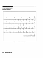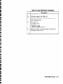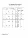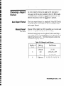
1
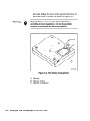
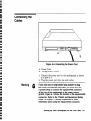
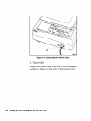
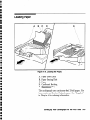
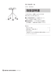
0
l
0
0
l
l
l
0
l
l
0
0
l
0
l
l
0
0
0
0
*
0
l
l
l
a
l
a
l
a
a
e
l
e
l
l
a
0
l
0
l
PageWriter 100
HP M1772A Cardiograph
User’s Guide
m
HEWLETT
PACKARD
HP Part No. M1772-91900
Printed in USA February 1996
Edition 3
E0296
Notice
The information in this document is subject to change
without notice.
Hewlett-Packard makes no warranty of any kind on
this material, including but not limited to, the implied
warranties of merchantability and fituess for a particular
purpose. Hewlett-Packard shall not be liable for errors
contained herein or for incidental or consequential
damages in connection with the furnishing, performance,
or use of this material.
This document contains proprietary information which is
protected by copyright. All rights are reserved. No part
of this document may be photocopied, reproduced, 01
translated to another language without the prior written
consent of Hewlett-Packard Company.
Before using the instrument, read this guide and become
thoroughly familiar with the contents.
Responsibility of the Manufacturer
Hewlett-Packard only considers itself responsible for
any effects on safety, reliability and performance of the
equipment if:
assembly operations, extensions, re-adjustments,
modifications or repairs are done by persons
authorized by Hewlett-Packard, and
the electrical installation of the relevant room complies
with the IEC or national requirements, and
the instrument is used according to the instructions
for use presented in this manual.
0
0
a
l
0
l
a
l
0
l
a
a
a
0
l
l
0
0
a
0
l
a
a
a
0
a
l
a
a
l
0
a
a
a
a
l
a
a
a
a
0
l
0
0
0
Warning
@
As with all electronic equipment, radio frequency
interference between this cardiograph and any existing
RF transmitting or receiving equipment at the installation
site, including electrosurgical equipment, should be
evaluated carefully and any limitations noted before
the equipment is placed in service. Monitoring during
electrosurgery should not be attempted and monitoring
electrodes should be removed from the patient to
preclude the possiblity of burns. Radio frequency
generation from electrosurgical equipment and close
proximity transmitters may seriously degrade cardiograph
performance. Hewlett-Packard assumes no liability
for failures resulting from RF interference between HP
medical electronics and any radio frequency generating
equipment at levels exceeding those established by
applicable standards.
This is to certify that this equipment is in accordance
with the Radio Interference Requirements of the EMC
Directive.
Warning
Use of accessories other than those recommended by
Hewlett-Packard may compromise product performance
and/or product safety.
THIS PRODUCT IS NOT INTENDED
USE.
FOR HOME
@ Copyright 1994, 1995 Hewlett-Packard Company.
Printing History
iv
September 1994
Edition 1
April 1995
Edition 2
February 1996
Edition 3
l
a
0
l
a
l
a
0
a
0
a
l
l
0
0
0
0
l
0
0
a
a
0
0
0
a
a
a
a
Q
a
l
0
a
0
l
l
a
a
a
a
a
a
0
0
Safety Summary
Safety Symbols
Marked on the
Cardiograph
The following safety symbols are used on the
cardiograph.
A!
Caution - See operating instructions.
Meets IEC type CF leakage current requirements
and is defibrillator protected (Isolated ECG
input).
Alternating current.
Equipotential (identifies independent protective
earth conductor to the cardiograph).
Fuse.
Indicates power control for cardiograph.
Hz
Indicates operating frequency in cycles per second.
Please see “Patient and Operational Safety Notes” in
Chapter 1, Getting Acquainted, for further information
about operating your cardiograph safely.
V
Conventions Used
in This Manual
Warning
Caution
Note
9
Warning statements describe conditions or actions that
can result in personal injury or loss of life.
Caution statements describe conditions or actions that
can result in damage to the equipment or software.
IF)
Notes contain additional information on cardiograph
I usage.
Yb
@
vi
Represents keys on ‘the front panel.
0
0
a
0
0
l
l
0
0
l
0
0
0
0
0
0
0
0
0
0
0
0
0
l
l
l
l
a
a
a
0
0
0
0
0
l
l
0
0
0
0
l
0
0
l
Contents
1. Getting Acquainted
The Keyboard and Front Panel .....
About Your Cardiograph .......
Accessories ............
About This Manual ..........
Patient and Operational Safety Notes . .
AC and DC (Battery) Operation ....
2. Recording an ECG
Preparing the Patient .........
Understanding When a Signal is Acquired
Recording an Auto ECG ........
Correcting a Leads Off Condition ...
Auto Report Filters ..........
Making Copies of Auto ECGs .....
Recording a Manual ECG .......
Changing Manual Report Settings . .
Restoring the ECG Trace After
Defibrillation or Reconnecting Leads
Manual Report Filters .........
Understanding the Printed Report ...
Choosing a Report Format .......
Auto Report Format ........
Manual Report Formats .......
An Auto Report Example ......
Manual Report Examples ......
1-4
1-6
1-6
1-7
1-8
1-10
2-2
2-3
2-4
2-4
2-5
2-6
2-7
2-8
2-8
2-9
2-10
2-13
2-13
2-13
2-14
2-15
Contents-1
3. Troubleshooting
Checking ECG Technique .......
Identifying ECG Problems .......
If the Recording Won’t Start .....
If the Cardiograph Won’t Print a
Manual Report .........
4. Maintaining the Cardiograph
Care and Cleaning ..........
Cleaning the Cardiograph ......
Cleaning the Electrodes and Cables . .
Cleaning the Digital Array Printhead
and Paper Sensor .......
Loading the Paper ..........
Storing the Paper and Patient ECG
Records ............
........
Caring for the Battery
Storing the Battery .........
Replacing the Fuses ..........
Supplies ...............
Calling for Service ..........
United States of America ......
Canada ..............
Other International Areas ......
A.
Contents-2
3-1
3-2
3-3
3-5
4-1
4-1
4-2
4-3
4-5
4-6
4-8
4-9
4-9
4-11
4-14
4-14
4-14
4-14
Setting up Your Cardiograph for the First Time
A-2
Checking the Voltage Setting ......
A-4
The Battery .............
A-4
Installing the Battery ........
Removing the Battery ........
A-5
A-7
Connecting the Cables ........
A-9
Loading Paper ............
0
0
l
l
0
0
l
0
0
0
0
0
0
l
0
0
0
0
l
0
a
0
0
a
l
a
l
0
0
l
l
0
0
l
0
l
l
l
l
0
0
0
0
l
0
.: 1,:
;a, , . .,I< :.,
;’
B.
.*.
I,‘.
Specifications
Basic Controls . . . . . . . .
Frequency and Impulse Response
Instrument Test . . . . . . .
Patient Safety . . . . . . . .
Power and Environment . . . .
.
.
.
.
.
.
.
.
.
.
.
.
.
.
.
.
.
.
.
.
B-1
B-1
B-2
B-2
B-2
Glossary
Index
Contents-3
Figures
.
1-1. The PageWriter 100 Cardiograph.
1-2. Bottom View of Cardiograph . . . .
1-3. The Keyboard and Front Panel of the
Cardiograph. . . . . . . . . .
2-1. The Auto ECG Report. . . . . . .
2-2. An Auto 3x4 ECG with One Rhythm
Strip(3x4, 1R). . . . . . . . .
2-3. A Manual S-Lead ECG. . . . . . .
2-4. A Manual 6-Lead ECG. . . . . . .
4-1. Cleaning the Digital Array Printhead.
4-2. Loading the Paper. . . . . . . . .
4-3. The AC Fuse Holders. . . . . . . .
A-1. Rear View of Cardiograph . . . . .
A-2. Removing the Battery Door. . . . .
A-3. The Battery Compartment. . . . .
A-4. Connecting the Power Cord. . . . .
A-5. Connecting the Patient Cable. . . .
A-6. Loading the Paper. . . . . . . . .
.
.
1-2
1-3
.
.
1-4
2-10
.
.
.
.
.
.
.
.
.
.
.
.
2-14
2-15
2-16
4-3
4-5
4-10
A-3
A-5
A-6
A-7
A-8
A-9
Tables
2-1.
2-2.
2-3.
2-4.
2-5.
2-6.
Contents-4
Leads Off Labels . . . . . .
Auto Filter Settings . . . . .
Manual Filter Settings . . .
Auto ECG Report Annotations
Calibration Signals . . . . .
Manual Lead Groups . . . .
.
.
.
.
.
.
.
.
.
.
.
.
2-5
2-5
2-9
2-11
2-12
2-13
l
l
l
l
l
l
l
l
l
.:..
‘,
3-1. ECG Problems and Solutions
. . . .
3-2
l
6
l
e
l
l
l
l
l
l
l
a
l
e
l
l
l
l
l
e
l
l
l
e
l
l
l
l
l
l
l
Contents-5
s
e
l
I@
9
io
*a,
9
*
e
0
a
,e
.1)
#
e
l
0
e
,*
@
0
0
;a
0
a
,c)
e
l
0
0
0
0
b
8
,;o
a
9
0
0
.e
9
l
9
10
Getting Acquainted
A
w
:
l
l
l
l
l
l
l
l
l
l
l
l
l
l
l
0
l
l
l
l
l
l
l
l
l
l
l
l
l
0
l
0
:
l
:
=
m
w
a=A
=A
=-a
=
1
Getting Acquainted
This chapter describes to the new user the many
features of the PageWriter 100 cardiograph, patient and
operational safety, and AC/battery operation. The user
should become familiar with this material, especially the
safety information, prior to using the cardiograph.
Note
I
!i?
See Appendix A, Setting up Your Cardiograph for the
First Time for information on checking the voltage
switch setting, installing the battery, connecting the
cables, and loading paper. Each of these tasks must be
done prior to operating the cardiograph for the first
time.
Getting Acquainted
1-1
Figure 1-l. The PageWriter 100 Cardiograph.
A. Patient Cable
B. Cardiograph
1-2 Getting Acquainted
0
0
0
0
0
l
0
l
0
l
0
l
0
l
l
l
l
l
0
0
a
l
l
0
0
0
l
l
l
l
0
0
0
l
0
0
l
l
0
l
:
0
=
l
Figure 1-2. Bottom View of Cardiograph
A. AC Fuse Holders
B. Mounting Point for M1705B Cart
(Mounting screw included with cart)
C. Battery Door
Getting Acquainted
1-3
The Keyboard and
Front Panel
-
/qEigi!~,II,~,
-
Figure 1-3. The Keyboard and Front Panel of the Cardiograph.
1-4 Getting Acquainted
M1772-01
,
=v
rw
av
A
v
:
0
0
0
0
0
0
a
l
0
l
0
0
l
l
0
0
0
0
l
0
l
0
l
l
0
0
a
0
0
0
0
0
l
e
m
w
aw
*w
ea
*
w
Ij
A
Instructions
This text describes how the front-panel lights indicate the
operating status of the cardiograph:
Attention:
A flashing Auto light indicates that the ECG is being acquired.
When the light stays on, the acquisition is complete.
A flashing Chart Speedlight indicates a paper supply problem.
A flashing Manual lead group light indicates an electrode
connection problem.
B
AC
C
Low Battery
D
l-1
(g
giiqz-SpeedJ
0
pzzSize_)
(TJ (\/)
(zJ=
Light will be on when the power cord is plugged into AC power.
This also indicates that the battery, if installed, is charging.
This light indicates that the cardiograph must be plugged in to
recharge the battery.
Switches the cardiograph between On and Standby. Standby
means the,cardiograph is off but it is still keeping the battery
charged as long as the cardiograph is plugged into AC power.
Sequentially changes the chart speed from 5, j 10, =+ 25, 3 50,
=+ 5 mm/second.
Sequentially changes the limb and chest lead sensitivity from 5, z+
10, 3 20, * 5 mm/mV.
Reduces the chest lead sensitivity to 50% of the value set by
g?CTiZSize).
Turns the Baseline Wander and Noise filters on or off. See “Auto
Report Filters” in Chapter 2, and “Manual Report Filters” in
Chapter 2 for more information.
Advances the paper to the beginning of the next page.
Starts an Auto ECG recording.
Starts a Manual ECG recording.
Sequentially changes the lead group used to generate a Manual
ECG from I II III, 3 aVR aVL aVF, j II aVF V2, j Vl-V6, j
I II III.
Halts any cardiograph function.
Prints a copy of the last Auto ECG. If you want additional copies
of an Auto ECG, you must print them before recording another
Auto or Manual ECG.See “Making Copies of Auto ECGs” in
Chapter 2, Recording an ECG for more information.
Getting Acquainted
1-5
About Your
Cardiograph
Your PageWriter 100 cardiograph:
l
n
n
n
n
Accessories
Acquires 12 leads simultaneously.
Provides selectable Manual formats.
Operates on a rechargeable battery. AC power charges
the battery.
Has a digital array printer with continuous-feed paper.
Has a 200 sheet Z-fold paper capacity.
Your cardiograph was shipped with one of three
accessory sets, according to your geographic option:
No Electrodes - Options: ABB, ABD, ABE, ABF,
ABH, ABS, ABU, ABX, ABZ, ACQ
n
n
n
n
n
Power cord
Patient Cable
1 package of paper
PageWriter 100 User’s Guide
Using the HP PageWriter 100 Cardiograph operator
training video
For electrodes, contact your local Hewlett-Packard Sales
Office or your authorized Hewlett-Packard Dealer or
Distributor.
Reusable Electrodes ABZ, AB4, AKV
n
n
n
n
n
n
n
n
1-6 Getting Acquainted
Options: ABG, ABK, ABM,
Power cord
Patient Cable
1 package of paper
6 Welsh bulb electrodes
4 limb electrodes and straps
1 tube Red&@ creme
PageWriter 100 User'sGuide
Using the HP PageWriter 100 Cardiograph operator
training video
0
:
0
l
0
0
l
0
0
0
l
l
l
l
0
l
l
l
l
e
0
8
0
l
0
0
l
0
l
l
l
l
a
l
0
0
l
l
0
0
l
l
a
0
l
3
,,
I’
Disposable Electrodes -
Options: ABA, ABC
I Power cord
n Patient Cable
n 1 package of paper
n Disposable electrode starter set
n Tab electrode adapters
n Page Writer 100 User’s Guide
n Using the HP Page Writer 100 Cardiograph operator
training video
About This Manual
This guide contains concise operating instructions
for cardiograph users. This manual describes how to
perform the following tasks:
n Recording an ECG
H Troubleshooting
n Caring for and maintaining the cardiograph
n Preparing your cardiograph for use
Getting Acquainted
1-7
Patient and
Operational Safety
Notes
Your cardiograph isolates all connections to the patient
from electrical ground and all other conductive circuits
in the cardiograph. This reduces the possibility of
hazardous currents passing from the cardiograph through
the patient’s heart to ground. To ensure the patient’s
safety and your own, observe the following reminders.
When operating your cardiograph from AC power, be
sure it and all other electrical equipment connected to
or near the patient are effectively grounded.
Use only grounded power cords (three-wire power
cords with grounded plugs). Also make sure the
outlet accepts the plug and is grounded. Never
modify a grounded plug to fit an ungrounded outlet,
i.e. removing the ground prong or ground clip to
fit an ungrounded outlet. Should an ungrounded
plug adapter be necessary,use a ground strap to
connect the equipotential connector at the rear of the
instrument to the power source ground.
The patient cable should be routed away from power
cords and any other electrical equipment. Failure to do
so can result in AC line frequency interference on the
ECG trace.
Warning
The HP patient cable supplied with this cardiograph, or an
approved HP substitute patient cable, is an integral part
of the cardiograph’s safety features. Using any other
patient cable may compromise defibrillation protection as
well as performance.
Only qualified personnel may service the cardiograph.
1-8 Getting Acquainted
re
r
a
G
l
0
l
*
9
a
0
0
Q
a
1)
*
II)
Q
@
0
a
0
*
0
*
3
‘,
0
0
l
l
9
0
l
a
l
0
Q
l
a
l
9
0
l
.
-.
,
Warning
‘, I.
I./,
1L ,
:
,’
Do not use this cardiograph near flammable anesthetics.
It is not intended for use in explosive environments.
Do not touch the patient, patient cable or cardiograph
during defibrillation procedures. Death or injury may
occur from the electrical shock delivered by the
defibrillator.
Be sure that the electrodes or leadwire tips do not come
in contact with any other conductive parts, including
earth-grounded parts, especially when connecting or
disconnecting electrodes to/from a patient.
The use of multiple instruments connected to the same
patient may pose a safety hazard due to the summation
of leakage currents from each of the instruments. Any
such combination should be evaluated by local safety
personnel before being put into service.
Do not pull on the paper while a report is being printed.
This can cause distortion of the waveform and can lead to
potential misdiagnosis.
Caution
Do not block the ventilation slots located on both sides
and to the rear of the cardiograph. Lack of ventilation
may cause cardiograph to overheat and components to
fail.
n
The Hewlett-Packard warranty is only assured if
you use Hewlett-Packard approved accessoriesand
replacement parts.
Getting Acquainted
1-9
Your cardiograph requires the battery to be installed for
proper operation-even if the cardiograph is plugged into
AC power, it cannot print an ECG report without the
battery. For information about replacing or installing
the battery, refer to Appendix A, Setting up Your
Cardiograph for the First Time.
AC and DC
(Battery)
Operation
The following is a list of AC and battery operating
instructions:
m A fully charged battery (without AC power) will print
approximately 40 Auto ECGs, or approximately 40
minutes of continuous Manual ECG information.
m The Low Battery light indicates the battery needs to
be charged. If the Low Battery light begins to flash,
this indicates the cardiograph is about to shut down
due to a very low battery. Plug the cardiograph into
AC power.
n
From the time the Low Battery light first comes on to
when the cardiograph automatically turns itself to
Standby (off), there is typically enough reserve battery
capacity to print two Auto ECG reports or 2 minutes
of Manual ECG data. A weak or faulty battery will
reduce this time.
H A discharged battery requires at least 5 minutes
charging time, with the cardiograph in Standby (off),
to print an Auto ECG.
n
Note
I
!I@
1-10 Getting Acquainted
A discharged battery requires at least 10 minutes
charging time, with the cardiograph in Standby (off),
to print a l-minute Manual ECG.’
If the cardiograph is turned on while the battery is being
charged, these charging times are doubled (10 minutes
for an Auto ECG and 20 minutes for a l-minute Manual
ECG).
0
0
0
l
l
l
l
l
l
0
l
l
0
0
0
0
l
l
l
0
0
l
l
0
l
0
l
l
l
l
l
l
l
0
0
0
l
l
0
l
l
l
a
0
0
n
The PageWriter 100 cardiograph has a battery-saving
feature: it will turn itself to Standby (off) after
30 minutes of instrument inactivity. This prevents
the cardiograph from being accidentally left on for
extended periods of time.
This feature is not active if all the limb electrodes
are connected to a patient or if the cardiograph is
plugged into AC power.
I A new.battery or a battery that has been stored for
an extended period of time requires charging (with the
cardiograph in Standby (off)) for 16 hours.
n
The battery, if installed, is being charged any time the
AC light is on.
n
A fully depleted battery will charge to 90% of full
capacity in 7 hours, and 100% capacity in 16 hours,
as long as the cardiograph is in Standby (off) for the
entire time.
m When the cardiograph is not in use, it should be
connected to AC power and left in Standby (off). This
will maintain a full battery charge and prolong battery
life.
Note
I
rg
The cardiograph’s battery charging circuit delivers less
power than the cardiograph uses while printing an ECG.
If a Manual ECG is being recorded, the battery charge
level will continue to drop until the instrument shuts
itself down or is turned to Standby (off) by the operator.
Getting Acquainted
1-11
*
=
A
=
*
v
*
w
a
w
:
l
0
l
l
e
0
l
0
0
l
l
l
0
0
a
l
l
0
l
a
l ’
l
l
l
0
l
0
0
0
l
l
l
l
l
l
l
l
0
0
Recording an ECG
0
0
l
l
0
l
0
0
0
0
0
l
0
l
0
0
l
0
0
0
l
l
l
l
l
0
0
l
l
l
l
0
0
0
0
a
0
l
0
l
0
l
l
0
0
2
Recording an ECG
This chapter describes how to prepare the patient for an
ECG, record an ECG, understand the printed report,
and change the ECG report format. Samples of the Auto
and different Manual report formats are also shown.
1
Note
Q
If the cardiograph has not been setup, refer to
Appendix A for instructions.
The basic steps and procedures for recording an ECG
are as follows:
1. If the cardiograph is not On, press (On/Standby).
2. Prepare the patient and apply the electrodes, as
described in the “Preparing the Patient” section.
3. Press (Auto)or (jZZZ) to record the ECG.
4. Check the quality of the recorded ECG on the printed
report.
The rest of thjs chapter discusses the details of setting
up and recording ECGs and understanding the printed
report.
Recording an ECG 2-1
For electrode placement information, refer to the
diagram on the top of your cardiograph. For tips on
proper ECG technique, see the videotape Using the HP
PageWriter 100 Cardiograph.
Preparing the
Patient
Note
1
Yb
Proper patient preparation and electrode placement are
the most important elements in producing a high quality
ECG trace.
Prepare the patient by performing the following steps.
1. Reassure and relax the patient. A calm and quiet
patient produces the best ECGs.
2. Make sure each electrode site is not covered by hair or
clothing.
3. Gently clean and abrade the surface of the skin with
dry gauze.
4. Place electrodes on patient. See the notes below
regarding your type of electrodes.
Note
1
Yb
The patient cable should be routed away from power
cords and any other electrical equipment. Failure to do
so can result in AC line frequency interference on the
ECG trace.
Notes for Customers Using Reusable Electrodes
Each electrode must be attached securely. Straps must
neither slide nor be so tight as to cause discomfort.
The electrode paste, gel, or creme must cover an area the
size of the electrode, but must not extend beyond it,
especially on the chest.
Notes for Customers Using Disposable Tab Electrodes
Disposable electrodes have conductive material on one
side only, the adhesive side. The electrode tab must be
2-2 Recording an ECG
0
0
l
a
0
l
0
0
0
0
0
l
0
e
a
l
0
0
a
l
0
0
0
0
@
l
l
l
a
0
l
0
0
a
l
a
*
l
e
l
l
l
a
a
0
placed between the jaws of the electrode adapter and
remain flat. Do not attempt to place the jaws of.the
electrode adapter so close to the circular part of the
electrode that the tab of the electrode is bent or contact
is made with the conductive gel. Gently tug on the
electrode adapter to ensure that the electrode adapter is
properly placed on the electrode.
Good and accurate placement on the first attempt
should be your goal for each electrode. Each time an
electrode is lifted off the skin and attached again, the
conductive gel becomes weaker and less effective.
Understa
------- Jnding
When a Signal is
Acquired
Your PageWriter 100 cardiograph attempts to acquire
a.good signal for an Auto report before you press the
(Auto)key. Hewlett-Packard cab this Pre-acquisition.
Pre-acquisition is activated when the cardiograph is
turned on and remains active until an Auto report
begins to print. Pre-acquisition is deactivated by
printing an Auto report to allow for copies of the Auto
report to be printed (see “Making Copies of Auto
ECGs”). Pre-acquisition is also deactivated whenever an
electrode is disconnected.
Pre-acquisition is reactivated when a Manual report is
finished printing.
When Pre-acquisition is active, it is important for the
patient to stay still and relaxed. This will help ensure a
good signal is captured prior to printing an Auto report.
Note
I
VI
Pre-acquisition is not used for Manual ECG reports.
Manual ECG reports display ECG data in real-time.
Recording an ECG 2-3
Recording an Auto
ECG
To record an Auto ECG, perform the following steps.
1. If the cardiograph is not On, press (WlL).
The
front panel lights are lit as the cardiograph performs a
short power-on sequence.
2. Prepare the patient and apply the electrodes.
3. Press (Auta)on the front panel.
The light above the (Auto) key flashes while the
cardiograph is acquiring the ECG. (If the IAuto)
light flashes in an alternating pattern with the
(Manual)lights a leads off condition is indicated. See
“Correcting a Leads Off Condition” below.) When
the cardiograph begins printing the ECG, the (Auto)
light stays on. When the cardiograph has completed
the report, the light turns off.
Correcting a Leads
Off Condition
A leads off condition is caused by the patient cable
not being connected to the cardiograph, one or more
leadwires not being connected to electrodes, or poor
contact between the patient and one or more electrodes.
The cardiograph signals a leads off condition only
during the acquisition of an Auto ECG. The operator
can check for a leads off condition anytime an ECG
report is printed by checking for traces consisting of
dashed lines or by checking the upper left corner of the
Auto ECG report for a leads off message. The leads off
messagelists the lead wires or electrodes that have a
leads off condition. Table 2-1 shows the possible leads off
messages,and the lead wire and electrode to check for
each one. To correct a leads off condition, perform the
following steps.
1. Check that the patient cable is properly connected.
2. Recheck the steps you performed when preparing
the patient. Pay particular attention to the proper
application of the electrodes and the connections
between leadwires and electrodes.
2-4 Recording an ECG
e
e
e
e
4
ti
i
aa
I
0
1)
a
0
0
3
l
a
I)
*
ii)
0
0
a
a
l
0
l
e
a
l
e
0
I)
a
l
9
l
a
l
l
l
9
9
l
0
‘*
_>.,,_)
-.
;
I’
Table 2-1. Leads Off Labels
Meaning
Designator
(AHA/IEC)
RL/N
Right leg electrode not connected, or only right leg electrode is
connected and all other limb electrodes are not connected.
RA/R
Right arm electrode is not connected.
LA/L
Left arm electrode is not connectd.
LL/F
Left leg elecrode is not connected.
Vl . . . V6/
Cl . . . C6
One or more chest electrodes are not connected. For example, V2
means the V2 electrode is not connected.
Auto Report Filters
The PageWriter 100 allows you to choose between two
sets of filters for Auto ECG reports:
I The 0.15-40 Hz filters (0.15 Hz Baseline Wander and
40 Hz Noise) are enabled when the Filter light is on.
It delivers the least amount of noise.
m The 0.15-150 Hz filters (0.15 Hz Baseline Wander and
150 Hz Noise) are enabled only when the Filter light
is off. It delivers the highest fidelity signal, but unless
ECG signal conditions are excellent, it can record
noise.
Table 2-2 shows when each filter is enabled.
Table 2-2. Auto Filter Settings
Default (Filter light on) Filters Off (Filter light off)
0.15-40 Hz
0.15-150 Hz’
1 Conforms to AAMI specifications
Recording an ECG 2-5
Making Copies of
Auto ECGs
If you require additional copies of an Auto ECG, you
may copy the last ECG that was recorded.
To copy your most recent Auto ECG, press the Icopy)
key.
Note
3
2-6 Recording an ECG
w You must copy the ECG before the cardiograph has
been turned to Standby (off) and before another ECG
has been acquired.
n You may change the speed (25 or 50 mm/set) prior to
printing a copy of an ECG.
w You can only print copies of Auto ECGs.
0
0
0
l
l
l
l
l
0
0
0
l
l
0
0
l
l
l
l
0
a
a
0
0
0
l
l
l
0
a
0
l
a
0
0
0
0
a
a
0
0
0
l
0
0
Recording a
Manual ECG
To record a Manual ECG, perform the following steps.
1. If the cardiograph is not On, press (On/Standby).The
front panel lights are lit as the cardiograph performs a
short power-on sequence.
2. Prepare the patient and apply the electrodes.
3. Press (?J until the light above the desired lead group
is lit.
4. Choose the desired (Speed],
(Sire),
and (VLeads)
sensitivity.
5. Press (Manua)on the front panel.
6. Inspect the ECG as it prints.
If any of the traces consist of a dotted line,
signifying leads off, press [Stop)and refer to
“Correcting a Leads Off Condition”.
If you would like to try to improve one or more
leads, press (Stopj and adjust the electrodes
accordingly.
After making adjustments, press (Manual_)
to restart
the recording.
The cardiograph will print the ECG continuously
until you press the IStop)key.
Note
I
‘4$
If accurate ECG ST contours are required in Manual
mode, turn off the (Filter key to activate the 0.15-150 Hz
filters. See “Manual Report Filters” for more details.
Recording an ECG 2-7
Changing Manual
Report Settings
The following Manual report settings can be changed
while a Manual report is printing:
n (Tiz-gi-Speed)
n (ECG)
n
(V)
sensitivity
n IF;lter)
I Lead group selection ((7-J)
Each can be changed by pressing the appropriate
key. There is no need to press (Stop)prior to changing
settings.
Restoring the ECG
Trace After
Defibrillation or
Reconnecting Leads
2-8 Recording an ECG
After an application of a defibrillator pulse, reconnecting
one or more leads, or any other time the ECG trace
is off-center during a Manual report, the trace can be
quickly restored by pressing the CManua/)
key again.
l
l
l
l
l
l
l
l
l
l
l
l
l
l
l
l
l
l
l
l
l
l
l
l
l
l
l
l
l
l
l
l
l
l
l
l
l
l
l
l
l
l
l
l
l
Manual Report
Filters
The PageWriter 100 allows you to choose between two
sets of filters for Manual ECG reports:
H The 0.05-40 Hz filters (0.05 Hz Baseline Wander and
40 Hz Noise) are enabled when the Filter light is on.
It delivers the least amount of noise.
w The 0.05-150 Hz filters (0.05 Hz Baseline Wander and
150 Hz Noise) are enabled only when the Filter light
is off. It delivers the highest fidelity signal, but unless
ECG signal conditions are excellent, it can record
noise.
Table 2-3 shows when each filter is enabled.
Table 2-3. Manual Filter Settings
Default (Filter light on) Filters Off (Filter light off)
0.05-150Hz1
0.05-40 Hz
1
1 Conform to AAMI specifications
Recording an ECG 2-9
Understanding the
Printed Report
I
.M
A
“1
I
I”1
I
I
I
VI
I
v*
$---
I
“6
pJ-zcq+,+,
Figure 2-1. The Auto ECG Report.
2-10 Recording an ECG
:
:
l
l
l
0
l
l
l
l
l
l
l
l
l
l
l
l
l
l
l
l
l
l
l
l
l
l
l
e
l
l
l
l
l
l
l
l
l
l
l
l
l
l
l
Table 2-4. Auto ECG Report Annotations
1
Description
Leads off indicators
Calibration signal. See Table 2-5.
Cardiograph settings for speed and for limb and
chest lead sensitivity.
Filter settings:
* AC filter ( w)
* Frequency range
i * Baseline Wander filter (W).
Sequence number, the total number of ECGs the
cardiograph has recorded.
Recording an ECG 2-11
The following table shows how the height of the
calibration pulse indicates ECC: sensitivity.
Table 2-5. Calibration Signals
ECG Size (nun/n~V)
ECG Size
nun/xnV
[\/I
Iudicator
Limb Leads
V Leads
(Vl - VG)
Calibration
Auto
Pulse
Manual
Limb Leads
off 5
i
on
i
10
10
ofi 10
on
!O
!O
2-12
5
10
5
V Leads
nn
r-l
2.5
VA--l
r-t
10
nrl
l-l
5
l-5l-l
n
2o
nn
n
r-A-l
r-l
off 20
on
Recording an ECG
20
10
e
w
:
l
0
0
0
0
l
l
0
0
l
0
0
l
l
0
0
l
l
0
l
0
l
0
l
0
l
l
a
0
0
l
0
0
0
l
l
5
=
a
i
0
,
Choosing a Report
Format
An Auto report prints a one-page (at 25 mm/set) or
two-page (at 50 mm/set) summary of all 12 ECG leads.
A Manual report presents a continuous printout of the
selected lead group until the (Stop)key is pressed.
Auto Report Format
The Auto report format is a standard 12-lead ECG with
a lead II rhythm strip. Figure 2-2 is an example of the
auto report format.
Manual Report
Formats
Manual ECGs reflect the ECG waveform as it occurs and
there is no significant delay in the recording.
Alternate lead groups can be selected while recording a
3- or 6-lead ECG by pressing @ until the light above the
desired lead group is lit. The following table shows the
available lead group choices.
Table 2-6. Manual Lead Groups
1NE,of
1(z%,/
Lead Groups
Leftmost
I, II, III
2nd
aVR, aVL, aVF
3rd
II, aVF, V2
Rightmost
VI, V2, V3, V4, V5, V6
Recording an ECG 2-13
An Auto Report
Example
The following figure is an example of the Auto ECG
report format.
15 mm/r
IO mm,mv c 0.15 HI - IJO “1
Figure 2-2. An Auto 3x4 ECG with One Rhythm Strip(3x4, 1R).
2-14 Recording an ECG
00101
:
l
l
l
0
l
0
e
0
0
l
l
a
l
l
0
a
0
0
a
0
l
0
l
a
9
l
l
l
0
0
l
0
0
0
0
a
l
0
l
0
l
0
0
0
Manual Report
Examples
The following figures show examples of Manual ECG
report formats.
Figure 2-3. A Manual 3-Lead ECG.
Recording an ECG 2-15
n “’
15!nm,I
m/m”
5IO
0.0s
HZ- 10H,
Figure 2-4. A Manual C-Lead ECG.
2-16 Recording an ECG
ea
l
e
*
l
G
a
a
e
l
a
@
,r)
e
a
0
0
l
l
9
cc,
0
l
il)
a
;il)
a
‘*
e
a
*
a
a
i)
*
a
i
a
@
a
l
0
G
=
s
Troubleshooting
l
0
a
a
0
0
a
0
0
0
0
0
0
0
a
0
0
a
a
0
l
0
0
0
0
0
a
0
0
0
0
0
0
0
0
a
0
0
0
0
0
0
0
=
0
3
Troubleshooting
Your cardiograph is designed for reliable operation. If
you have problems with an ECG, there are several things
you can check before calling for service. This chapter
tells how to solve basic ECG problems.
Checking ECG
Technique
Many problems in taking an ECG may be related to
electrode application. Review “Preparing the Patient”
in Chapter 2, Recording an ECG to assure the patient
leads are properly attached to the patient.
Troubleshooting 3-1
Identifying ECG
Problems
The following table shows symptoms and solutions to
problems that can occur when recording an ECG.
Table 3-1. ECG Problems and Solutions
Cause
Problem
Power line AC
Interference
Poor electrodecontact. Dry or dirty
electrodes.
Reapply electrodes. Abrade skin.
Use new electrodes.
Lead wires may be picking up
Route electrode wires along the
interference.One possibility is a
limbs and awayfrom any other
poorly grounded instrument near
patient.
electrical equipment. Fix other
equipment. Unplug cardiograph
from AC power and operate on
battery only.
Move cardiograph further away frou
patient. Unplug cardiograph from
AC power and operate on battery
only. Move other instruments
further away from patient. Unplug
electric bed.
Patient cable is located too close to
the cardiograph’s power cord or
other power cords.
Wandering
Baseline
Possible Solutions
Patient movement.
Reassure and relax the patient.
Electrode movement. Poor electrode Be sure that the lead wires are not
contact & skin preparation.
puliing on the electrodes. Reapply
electrodes. Make sure the Filter
light is on.
Respiratory interference.
Move lead wires away from areas
with greatest respiratory motion.
3-2 Troubleshooting
0
0
l
l
l
l
0
l
0
0
l
0
0
a
0
l
0
l
*
l
l
l
0
0
0
0
0
0
0
l
0
0
0
l
0
0
0
0
l
0
:
0
0
0
Table 3-l. ECG Problems and Solutions (continued)
Possible Solutions
Cause
Problem
Tremor or Muscle Poor electrode placement. Poor
electrode contact. Patient is cold.
Artifact
Tense, uncomfortable patient.
LLL
Tremors.
Intermittent or
Jittery Waveform
Clean the electrode site. Reapply
electrodes. Be sure that the limb
electrodes are placed on flat,
non-muscular areas of the body.
Warm the patient.
Reassure and relax the patient.
Make sure the Filter light is on.
Attach electrodes high on the
extremities near the trunk.
Make sure the Filter light is on.
Poor electrode contact. Dry
electrodes.
Clean the site. Reapply electrodes.
Faulty lead wires.
Replace faulty patient cable.
Dirty printhead.
Clean the printhead.
Use HP recommended paper.
qj t tPoor print
quality (uneven
contrast or blank
streaks)
If the Recording
Won’t Start
If you press (Auto) or (Manual)and the recording doesn’t
start, investigate the following possibilities:
n
Is the cardiograph turned on?
At least one light other than the AC light should
be on.
n
Is the AC power light on?
If the cardiograph is plugged into AC power
and the AC light is not on, check the two line
fuses. See “Replacing the Fuses” in Chapter 4,
Maintaining
the Cardiograph
for fuse information.
Troubleshooting
3-3
n
Is the patient cable connected to the cardiograph?
Visually check the connection between the
cardiograph and the patient cable.
n
Is the battery adequately charged?
The Low Battery light should be off.
n
Is the cardiograph out of paper? Is the paper jammed
in the cardiograph?
The cardiograph will not record an ECG unless
you have loaded paper or cleared the paper jam.
See Appendix A! Setting up Your Cardiograph
for
the First Time for details on loading the paper.
Reloading the paper will clear a paper jam.
w Is the paper sensor lens dirty?
Clean the paper sensor lens. See Chapter 4,
Maintaining
the Cardiograph
for more information.
I Is the paper door completely closed?
Open the paper door slightly and close it tightly.
Listen for the door safety latch to lock.
If the cardiograph still won’t operate, perform the
following steps.
1. Switch the cardiograph to Standby (off) with the
(0n/Standby)switch.
2. Wait 20 seconds and then switch the cardiograph
back to On.
3. Press (Auto)or (Manual).If the cardiograph turns
itself to Standby (off), the battery is not operating
properly.
If the cardiograph still won’t operate, call your local
Hewlett-Packard service representative.
3-4 Troubleshooting
=
:
0
l
l
l
0
0
0
0
l
l
0
l
0
l
0
l
l
l
l
l
l
0
l
a
l
0
l
l
l
0
a
l
0
l
l
0
0
0
0
0
l
0
0
If the Cardiograph
Won’t Print a Manual
Report
n
Is the paper sensor lens dirty or obstructed?
Clean the paper sensor lens. See Chapter 4,
Maintaining the Cardiograph and Figure 4-l for
more information.
n
Is the cardiograph out of paper?
Load paper. See Loading the Paper in Chapter 4,
Maintaining the Cardiograph.
Troubleshooting
3-5
5l
l
l
l
0
0
l
l
l
0
0
l
0
0
0
l
0
l
0
l
l
l
l
e
l
l
l
0
l
0
0
0
0
l
l
l
0
0
l
l
l
l
0
Maintaining the Cardiograph
0
0
0
a
l
0
0
0
0
l
0
l
0
a
l
l
l
l
0
0
0
a
0
l
m
0
0
0
l
l
a
0
0
l
0
0
0
a
l
l
0
0
l
0
0
Maintaining the Cardiograph
Care and Cleaning
Cleaning the
Cardiograph
Caution
a
The outside surfaces of the cardiograph and its
accessories(except the patient cable) are designed
to be cleaned by mild soap and water or isopropyl
alcohol. The patient cable can be cleaned only with mild
disinfectant OTsoap and water. The patient cable cannot
be cleaned with isopropyl alcohol.
1. Unplug the power cord and ensure that the
cardiograph is in Standby mode (all lights are off).
2. Wipe the external surfaces of the cardiograph with a
soft cloth dampened with mild soap and water or
isopropyl alcohol. Avoid applying cleaning fluids to
the cable connectors.
Do not use any strong solvents or abrasive cleaning
materials.
Do not spill any liquids on the surface of the
cardiograph. Immediately have the cardiograph
serviced if any liquids spill on the surface of the
cardiograph.
Do not use the following to clean the cardiograph:
n Acetone
H Iodine-based cleaners
H Phenol-based cleaners
n Ethylene Oxide Sterilization
n Chlorine bleach
H Ammonia-based cleaners
Maintaining the Cardiograph 4-1
Cleaning the
Electrodes and
Cables
Clean the electrodes and patient cables with a soft cloth
moistened with a recommended disinfectant or cleaning
agent from the following list:
Cetylcide@ (may discolor cable)
Cidex@
Lysol@ Disinfectant
Lysol@ Deoderizing Cleaner (may discolor cable)
Dial@ Liquid Antibacterial Soap
ammonia
409@ (may discolor cable)
10% solution of Clorox@ in water (may discolor cable)
Murphy@ Household Cleaner, or
Ves-phene 118.
Wring any excessmoisture from the cloth before
cleaning.
Caution
$
I Do not clean the patient cable with alcohol. Alcohol
can cause the plastic to become brittle and may cause
the cable to fail prematurely.
n
Do not autoclave the cable or use ultrasonic cleaners.
n
The patient cable is not immersible.
m Do not use abrasive materials to clean metal
surfaces-scratches on them can cause artifacts.
n
Avoid wetting the connectors.
4-2 Maintaining the Cardiograph
e
a
l
l
*
*
e
8
l
a
l
0
e
e
e
a
l
a
0
e
@
@
a
0
@
*
i
l
l
*
l
l
e
e
l
l
l
a
a
a
0
l
e
.e
e
Cleaning the Digital Array Printhead and Paper Sensor
Figure 4-l. Cleaning the Digital Array Printhead.
A. Printhead
B. Paper Sensor
If the print quality is uneven, it may be due to a dirty
printhead. How frequently you must clean the printhead
dependson how many ECGs you print and the quality
and type of Paper you use.
If the Paperfails to stop at the end of a Page,the Paper
Sensorlens may be dirty.
Maintaining the Cardiograph
4-3
To clean the printhead:
Caution
a
Touch the equipotential connector on the back of the
cardiograph to discharge any static electricity stored on
your skin before touching the printhead. The printhead
can be damaged by static electricity.
1. From the front of the cardiograph, unlatch and open
the paper door. The printhead is to the right under
the paper blade and behind a brush. See Figure 4-1.
2. Wipe the printhead with a foam swab dipped in 90%
isopropyl alcohol. Scrub until all visible residues are
removed.
3. Dry the printhead with a clean lint-free tissue.
To clean the paper sensor lens:
1. From the front of the cardiograph, unlatch and open
the paper door. The paper sensor lens is to the right
under the printhead. See Figure 4-l.
2. Lightly wipe the paper dust off of the paper sensor
lens with a dry foam swab. Do not use alcohol.
4-4 Maintaining the Cardiograph
0
:
0
0
0
a
0
0
0
0
a
a
0
a
0
l
a
0
0
l
a
0
0
l
l
0
a
l
a
a
l
0
0
a
a
l
a
a
0
0
a
a
a
0
0
Loading the Paper
Figure 4-2. Loading the Paper.
A.
B.
C.
D.
E.
Paper Door Latch
Paper Sensing Hole
Paper
Cardboard Backing
(-Advance) Key
The cardiograph uses continuous-feed Z-fold paper. For
best results use Hewlett-Packard paper. See “Supplies”
for ordering information.
Maintaining the Cardiograph 4-5
To load the paper:
1. From the front of the cardiograph, release the latch on
the left side and slide the paper door to your left.
2. Remove the outer packaging on the paper stack.
3. Place the paper stack in the compartment so that the
top side of the paper feeds grid side up over the top
panel. The paper sensing hole will be in the lower
corner of the paper.
4. Pull a sheet halfway out and over the paper door.
Make sure that the paper lays on the black roller
evenly within the channel of the paper door. See
Figure 4-2.
5. Slide the paper door back into place. Make sure that
the door is latched.
to turn On the cardiograph, if
6. Press (On/StandbyL)
necessary. Press (-Advance) to advance the paper to
the beginning of the next page.
Storing the Paper and
Patient ECG Records
Recordings on standard chemical/thermal paper
decompose naturally over time. With proper storage and
handling, recordings on these papers have been shown to
be readable for approximately 5 years. Proper storage
and handling before and after recording includes:
1. Store the paper under cool and dry conditions.
Temperatures must not exceed 40 ’ C (104’ F) and
relative humidity must be below 80%.
2. Store recorded ECGs in manila folders, or in
sheet protectors made of polyester, polyimide,
polypropylene, or acetate, in areas as described above.
Do not store ECGs in vinyl sheet protectors, as noted
below.
Storing the paper as indicated above will minimize
trace fading and background development (darkening).
However, storing the paper as indicated above does not
protect against trace fading or background development
from the sources below.
4-6 Maintaining the Cardiograph
**
w
e
=
:
l
0
l
0
0
l
l
l
0
0
l
0
l
l
l
l
l
0
0
l
0
0
l
l
l
l
0
a
l
0
0
l
a
0
0
0
l
l
0
0
To avoid trace fading or background development, the
paper must not be exposed to or come in contact with
the following, either before or after recording:
l
Solvent-based adhesives, as used in mounting forms,
pressure-sensitive tapes, labels, and common mending
tapes. Starch- or water-based adhesives may be used.
I Plastics containing plasticisers, such as vinyl chlorides
(PVC) typically found in vinyl sheet protectors,
separators and plastic envelopes. Other plasticisers
include polyethylene glycol, dioctyl phthalate, and
dioctyl adipate.
n
Glossy (or non-glossy) papers containing tributyl
phosphate, dibutyl phthalate, or other organic
solvents, such as FAX and other non-chemical/thermal
recording paper, or product literature.
n
Liquid or vaporous solvents, such as alcohols, ketones,
esters, ethers, etc. Note that many of these solvents
are found in felt-tip and other marking pens.
w Petroleum-based solvents, such as toluene, benzene,
and gasoline.
w Bright light or UV sources such as sunlight, flourescent
and related light sources.
w Chemicals containing castor oil, ammonia, some
chemicals found in common hand and face creams, or
citric acid (found in fruit juices).
n
Forms containing carbon or carbonless (NCR) copy
sheets.
n
Pastes, creams or gels commonly used for ECG or
ultrasound tests that contain any of the above or
related chemicals.
If original recordings are stored, HP recommends
that records be checked annually to determine their
integrity. However, where long term storage is desired,
Maintaining the Cardiograph 4-7
the user should consider photocopying or microfilming,
or electronic or optical storage or a fade resistant paper.
HP’s PTPTM brand thermal papers offer improved
archivability. See “Supplies” for ordering information.
Caring for the
Battery
Your cardiograph requires the battery to be installed for
proper operation-even if the cardiograph is plugged into
AC power, it cannot print an ECG report without the
battery. For information about replacing or installing
the battery, refer to Appendix A, Setting up Your
Cardiograph for the First Time.
The sealed lead-acid battery used in the PageWriter 100
will provide optimum life when the unit is continuously
connected to AC power and fully charged after each
use. A depleted battery requires 16 hours of continuous
charge time to fully charge. Because it is not always
possible to allow a full charge cycle between uses, the
PageWriter 100 was designed to charge a depleted
battery to 90% of its capacity in approximately 7 hours.
Caution
a
Note
d
Repeated undercharging of the battery will damage the
battery and reduce battery life.
Hewlett-Packard recommends that the cardiograph be
plugged into AC power whenever possible to maximize
battery life.
Battery life varies by how the battery is maintained and
how much it is used. For improved battery life, keep the
instrument plugged in when not in use. If the battery
has been fully charged and requires recharging after a
few ECGs, consider replacing it. Use only HP battery,
part number M2460A.
4-8 Maintaining the Cardiograph
a
w
*
w
e
l
:
0
0
0
a
0
0
l
0
0
0
0
0
l
l
0
l
l
a
l
l
l
a
0
l
0
l
0
0
l
0
0
l
0
l
0
l
l
l
0
l
Note
J
Storing the Battery
Replacing the
Fuses
Battery should be removed from unit and placed in
storage if cardiograph will not be used for more than
three months without AC power.
To prepare the battery for storage, charge it in
the cardiograph for 16 hours. Then remove it from
cardiograph and store it in a cool, dry location.
Recharge a lead-acid battery in storage for at least 16
hours every six months. This ensures that the battery
does not completely discharge while in storage. The
battery’s shelf life is longer with cooler temperatures,
but do not store below freezing level.
To replace the AC fuses:
1. Unplug the cardiograph from AC power.
2. Turn the cardiograph bottom-side up.
3. Locate the two AC fuse holders on the bottom of the
cardiograph, as shown in Figure 4-3.
4. Using a screwdriver, turn the fuse cap l/2-turn
counter-clockwise. As the fuse cap is untwisted, it
extends above the surface of the cardiograph case.
5. Pull the fuse cap straight up approximately 2-l/2 cm
(l-inch), until it stops.
6. Remove the fuse. You may need to tap the fuse
holder to shake the fuse out.
7. Insert a new fuse in the holder, slide the fuse cap back
into the case. Fuse must be of the same type and
rating as described on the label located next to the
fuse holders.
8. Tighten the fuse cap l/2-turn
clockwise.
Maintaining the Cardiograph 4-9
9. Repeat the operation for the other AC fuse.
+/y -'.......,
<,,
-...
..~ 0
0
&.O
.$
Figure
4-3. The AC Fuse Holders.
A. AC Fuse holders (2)
4-10 Maintaining the Cardiograph
a
w
*
w
e
:
0
0
0
0
0
l
0
0
0
0
l
0
l
0
0
0
l
l
0
l
l
0
l
l
0
l
l
0
0
l
0
0
0
a
0
0
0
0
0
0
0
Supplies
Hewlett-Packard offers a full range of supplies for
cardiographs. The following list is a collection of
the most frequently ordered items. Pricing and
availability of these and other supplies are available from
Hewlett-Packard’s Medical Supplies Centers.
n
n
USA: Call l-800-225-0230
Outside USA: Please contact your local
Hewlett-Packard Sales Office or your authorized
Hewlett-Packard Dealer or Distributor.
Paper
M2481A
M2482A
M2483A
M2484A
M2485A
M2486A
Paper, 8.5” x 11”) 1600 sheets, with
header
Paper, 8.5” x 11”) 1600 sheets, no header
Paper, 210 x 300 mm, 1600 sheets, with
header
Paper, 210 x 300 mm, 1600 sheets, no
header
Paper, PTP brand Anti-fade, 8.5” x 11”)
1600 sheets, with header
Paper, PTP brand Anti-fade, 210 x 300
mm, 1600 sheets, with header
Maintaining the Cardiograph 4-11
Battery
M2460A
Battery assembly
Patient Cable
AHA Patient Cable with leads
M2461A
IEC Patient Cable with leads
M2462A
Carrying Case
Soft Carrying Case
M2463A
Redux
651-1021-010
651-1008-010
651-1024-010
40481B
4-12 Maintaining the Cardiograph
Redux
Redux
Redux
Redux
bottles
Creme; 4 oz tube; 10 tubes per box
Paste; 5 oz tube; 10 tubes per box
Gel; 4 oz tube; 10 tubes per box
Infant Creme; 5 oz bottle; 12
per box
fi
w
*
w
r
w
=
0
e
a
l
=
0
a
0
l
l
l
l
8
0
l
l
l
a
a
0
l
l
a
0
0
*
a
=
0
0
0
aw
*v
r
aa
ae*w
Electrodes
404903
Welsh electrode; 15mm base 5cc bulb;
screw connection(IEC)
Limb Plate Electrode(IEC) (4 per pack)
Welsh electrodes; 15mm base 5cc bulb;
push-in connection(AHA) (6 per box)
Limb Plate Electrode(AHA) (4 per pack)
15” Rubber strap for limb plate electrode
Disposable diagnostic pre-gelled electrode
(1,000 pieces)
Disposable diagnostic solid gel electrode
(1,000 pieces)
Disposable diagnostic solid gel electrode
(1,000 pieces) (United States and Canada
only)
Disposable diagnostic wet gel electrode
(300 pieces)
404913
40421A
40424A
14030A
40420A
13943B
13943D
13944B
Lead Adapters
Universal ECG Adapter (10)
13946B
14282A
Snap Electrode Adapter for &I1post leads,
spring clip (5 per box)
Snap Electrode Adapter for 4 mm banana
404983
leads, grabber (10 per box)
Cart
M1705B
Cart
Fuses
21lo-0620
2110-0930
AC fuse; 0.4 Amp 250 V
Battery fuse
,
Maintaining the Cardiograph 4-13
Calling for Service
United States of
America
HP Medical
Response Center
Tel: I-800-548-8833
Canada
Ceritral
Eastern Region
Region
Tel: l-800-361-9790 Tel: l-800-387-3900
Western Region
Tel: l-800-661-5626
Other International
Areas
European
Headquarters
France
Tel: 22 838-111
Tel: (1)60 77 80 00
Austria,
Gerxnany
Tel: 02102-9060
Eastern Europe
Tel: 0222125 00-333
Belgium
Mediterranean
Tel: 02/778 35 31
Tel: (41) 22 780 4111
and Middle
Netherlands
Spain
Tel: 20/547 69 11
Tel: l/637 00 11
Norway
Sweden
Tel: 2/24 60 90
Tel: S/444 22 30
Denmark
Tel: 2/81 66 40
Tel: 44 344 366 333
United
Kingdom
Finland
Italy
Tel: 90/887 21
Tel: 2/921 22 833
4-14 Maintaining the Cardiograph
East
a
:
za
l
1)
a
l
I)
*
‘0
*
.a
*a
e
l
e
*
a
0
*
0
I)
a
:a
*
a
c
l
9
a
0
,a
a
8
l
l
a
0
9
l
3
9
@
Setting up Your Cardiograph for the First Time
=
a
0
a
0
0
a
l
0
l
0
l
l
0
a
l
0
l
0
0
0
0
0
0
0
0
0
0
0
a
l
a
l
0
0
0
0
0
0
0
0
0
a
0
0
A
Setting up Your Cardiograph for the First Time
Before using your cardiograph for the first time you must
prepare it by performing the following tasks:
n Check the voltage setting
H Install the battery
n Connect the cables
n Load the paper
Setting up Your Cardiograph for the First Time A-1
Checking the
Voltage Setting
Your cardiograph can be set to operate at nominal line
voltages of 115 or 230 Volts (see the following Note).
The line voltage was set at the factory to the setting
for your area. However, it is a good idea to check this
setting. Refer to Figure A-l for the physical location of
the voltage select switch. To check the voltage setting,
perform the following steps.
1. Locate the voltage select switch on the back of the
cardiograph. See Figure A-l.
2. Verify that the correct voltage is visible on the
voltage select switch. If the voltage setting is
incorrect, slide the voltage switch so the correct
voltage is visible. The cardiograph operates with any
line frequency from 50 to 60 Hz.
3. Remove and discard the label that covers the AC
power receptable. See Figure A-l for the location of
the AC power receptable. The purpose of the label
is to remind you to check the setting of the voltage
select switch.
Caution
A-2 Setting
The cardiograph can be damaged if plugged into the
incorrect voltage.
upYour Cardiograph for the First Time
0
0
a
a
0
l
l
0
0
0
0
0
0
0
a
a
a
l
0
0
0
0
a
l
l
0
a
a
0
l
0
a
0
a
0
l
l
0
0
0
0
0
0
0
0
1
Note
!b
[. C-j@)
a
The nominal 115 VAC voltage setting works equally well
for any voltage between loo-120 VAC. The nominal
230 VAC voltage setting works equally well for any
voltage between 220-240 VAC.
Qj-JLW
;
,:.:
I4 Ei c
j
Figure A-l. Rear View of Cardiograph
A. Equipotential Connector
B. AC Power Receptacle
C. Voltage Select Switch
Note
I
w
The equipotential connector is only used when the
cardiograph must be plugged into an ungrounded
outlet. See “Patient and Operational Safety Notes” in
Chapter 1, Getting Acquainted for more information
about using the equipotential connector.
Setting up Your Cardiograph for the First Time A-3
Your cardiograph requires the battery to be installed for
proper operation-even if the cardiograph is plugged into
AC power, it cannot operate without the battery.
The Battery
Use only HP batteries, part number M2460A, in the
cardiograph.
Installing the Battery
To install the battery:
Do not remove the shrinkwrap surrounding the battery.
Note
Yii
Note
3
When you install the battery you may notice a screw
hole located near the battery compartment. This screw
hole is the mounting point for the optional M1705B cart.
The mounting thumbscrew is supplied with the cart.
1. Make sure the cardiograph is unplugged from AC
power.
2. Turn the cardiograph bottom-side up.
3. Slide the battery door in the direction of the arrow
until it unlatches (approximately l/2 inch), as shown
in Figure A-2. Lift off the door.
4. Install the new battery in the battery compartment as
shown in Figure A-3 and plug the battery connector
into the cardiograph.
5. Place the battery door into its slots and slide the door
in the opposite direction of the arrow until it latches,
as shown in Figure A-2.
6. Turn the cardiograph top-side up.
7. Plug the cardiograph into -4C power.
8. Check that the AC indicator light is on. The unit is
now in Standby (off) mode with the battery charging.
After you finish setting up the cardiograph, it may be
used on a limited basis until the battery has been fully
charged. Hewlett-Packard recommends charging the
A-4 Setting up Your Cardiograph for the First Time
0
0
l
0
l
l
0
0
l
0
0
0
0
l
a
l
0
l
l
0
l
l
0
l
l
l
a
l
e
l
0
0
0
l
0
0
l
0
l
0
0
0
0
0
0
r
battery as soon as possible for at least 16 hours. To
charge the battery, plug the cardiograph into the wall
outlet with the k-1
switch set to Standby (off).
I
MlTIo.02
Figure A-2. Removing the Battery Door.
A. Battery Door
Removing the Battery
To Remove the Battery:
1. Unplug the cardiograph from AC power.
2. Turn the cardiograph bottom-side up.
3. Slide the battery door in the direction of the arrow
until it unlatches (approximately l/2 inch), as shown
in Figure A-2. Lift off the door.
4. Unplug the battery connector from the cardiograph
by squeezing the edges of the connector and pulling it
straight out from the cardiograph.
5. Remove the battery and cable.
6. If the battery has been removed for storage, replace
the battery cover by placing the battery door into its
Setting up Your Cardiograph for the First Time A-5
slots and sliding the door in the opposite direction of
the arrow until it latches, as shown in Figure A-2.
Warning
Properly dispose of or recycle depleted batteries
according to local regulations. Do not disassemble,
puncture or incinerate the disposed batteries.
Figure A-3. The Battery Compartment.
A. Battery
B. Battery Cable
C. Battery Connector
A-6 Setting up Your Cardiograph for the First Time
=
:
a
a
0
a
0
0
0
0
0
0
0
0
a
a
0
a
a
0
0
0
0
0
0
l
l
0
0
0
a
0
l
l
0
l
a
0
a
0
0
0
0
a
a
Connecting the
Cables
Figure A-4. Connecting the Power Cord.
A. Power Cord
B. Voltage Select Switch
1. Connect the power cord to the cardiograph as shown
in Figure A-4.
2. Plug the power cord into the wall outlet.
Warning
0
If you must use an ungrounded plug adapter to plug
the power cord into the wall outlet, you must also use
a ground strap to connect the equipotential connector
at the rear of the cardiograph to the power source
ground. Figure A-l shows the location of the equipotential
connector. Refer to the “Patient and Operational Safety
Notes” in Chapter 1, Getting Acquainted for more
information about using the equipotential connector.
Setting up Your Cardiograph for the First Time A-7
Figure A-5. Connecting the Patient Cable.
A. Patient Cable
Connect the Patient cable to the front of the cardiograph
as shown in Figure A-5 and screw in both thumb-screws.
A-8 Setting up Your Cardiograph for the First Time
I*
I
c?:
l
l
0
0
0
l
l
l
0
l
l
l
a
e
a
a
0
0
l
0
0
l
l
a
0
l
0
0
a
e
a
0
0
l
0
0
a
0
l
0
l
Loading Paper
Figure A-6. Loading the Paper.
A.
B.
C.
D.
E.
Paper Door Latch
Paper Sensing Hole
Paper
Cardboard Backing
[Advance) Key
The cardiograph uses continuous-feed Z-fold paper. For
best results use Hewlett-Packard paper. See “Supplies”
in Chapter 4 for ordering information.
Setting up Your Cardiograph for the First Time A-9
To load the paper:
1. From the front of the cardiograph, release the latch on
the left side and slide the paper door to your left.
2. Remove the outer packaging on the paper stack.
3. Place the paper stack in the compartment so that the
top side of the paper feeds grid side up over the top
panel. The paper sensing hole will be in the lower
corner of the paper.
4. Pull a sheet halfway out and over the paper door.
Make sure that the paper lays on the black roller
evenly within the channel of the paper door. See
Figure A-6.
5. Slide the paper door back into place. Make sure that
the door is latched.
6. Press [?C/GG$ to turn On the cardiograph, if
necessary. Press (-Advance) to advance the paper to
the beginning of the next page.
A-10 Setting up Your Cardiograph for the First Time
G
l
l
0
*
0
0
a
l
co
*
‘e
9
0
*
*
e
l
e
0
@
a
0
b
a
e
9
0
l
I)
l
0
@
l
*
a
9
e
9
‘0
e
‘9
e
l
Specifications
0
0
0
l
0
a
0
0
0
a
a
0
l
0
0
0
0
0
0
0
0
0
a
0
0
0
l
0
0
0
0
0
0
0
0
0
0
0
a
0
0
a
l
0
0
Specifications
Conforms to applicable IEC, UL, AAMI, CSA
specifications.
Basic Controls
ECG Controls: On/Standby, Auto, Manual, Copy, Filter,
Page Advance (paper feed), Stop.
ECG Format Controls: Chart Speed, ECG size, V Leads
sensitivity. ECG Format Selections: Auto (3x4 with 1
rhythm lead); Manual (with 3 or 6 leads).
Frequency and
Impulse Response
Sinusoidal: 0.67 to 40 Hz &lo%
~~I$$~~~;;f~ecj
Displacement: Less than 0.10 mV
Slope: Less than 0.30 mV/sec
Each meets or exceeds AAMI ECll-1991 standard for
Diagnostic Electrocardiographic Devices.
Specifications
B-l
Instrument Test
A self-test may be started by pressing and holding
both the LAuto)and @G&i) keys while turning on the
cardiograph with the (On/Standby)
key. The instrument
performs an internal self-test. The test results are
printed on the report for use by service personnel. This
self-test runs continuously until the cardiograph is
turned to Standby (off).
Patient Safety
Patient Isolation: Less than 20 PA leakage with 120
VAC, 60 Hz or less than 50 PA leakage with 240 VAC,
50 Hz with patient cable.
Defibrillation Protection: Protected against damage from
400 joule defibrillator discharges.
Power and
Environment
Line Power: 100 to 120 VAC, 50 to 60 Hz (at 115 VAC
power-switch setting); 220 to 240 VAC, 50 to 60 Hz (at
230 VAC power-switch setting); 50 VA Maximum.
Fuse: 0.4 A for both the 115 and 230 VAC switch
settings.
Environmental Operating Conditions: 10 to 40” C (50 to
104” F), 15 to 80% relative humidity, non-condensing, up
to 4,550 m (15,000 ft.) altitude.
Environmental Storage Conditions: 0 to 50” C (32 to
122” F), 15 to 90% relative humidity, non-condensing, up
to 4,550 m (15,000 ft.) altitude.
Cardiograph Dimensions: 43 by 39 by 10 cm (17.0 by
15.3 by 3.9 in.).
Cardiograph Weight: 8.5 kg (19.8 lbs.).
B-2 Specifications
0
0
0
0
0
0
0
0
0
Glossary
0
l
l
0
0
0
0
0
0
0
0
a
a
a
0
0
l
0
l
a
l
0
0
0
0
a
l
0
0
l
a
0
0
:
0
0
l
0
0
l
0
0
l
0
0
0
0
0
0
0
0
0
0
l
0
0
0
l
0
l
l
l
l
l
0
l
0
0
0
l
l
0
l
l
l
0
0
0
Glossary
AC filter
A filter that screens out ECG artifact caused by
power line interference. This filter is built into the
cardiograph and cannot be disabled.
AHA leads
ECG lead names and identifying colors recommended
by the American Heart Association. Limb leads are
labelled RA, LA, LL, RL. Chest leads are labelled
Vl-V6. (See IEC leads)
alternating current (AC)
Electrical current provided by wall outlets. AC may
be either 60 or 50 Hz depending on country.
artifact
ECG waveform distortion that may diminish ECG
quality. ECG artifact (or noise) may be caused by
electrical interference, poor electrode connections, or
patient movement.
Auto ECG
Twelve-lead ECG recorded and analyzed over a ten
second period and printed in a predetermined format.
The PageWriter 100 prints Auto reports in a 3x4
format with one rhythm strip.
baseline wander
A slow upward or downward motion on the baseline
of any ECG waveform.
Glossary-1
baseline wander filter
Hewlett-Packard term for filter which reduces
baseline wander.
battery saver
Hewlett-Packard term for the cardiograph turning to
Standby automatically after a preset time period to
conserve power. The battery saver is factory set for
30 minutes of cardiograph inactivity.
calibration pulse
A 200 ms, 1 mV square or stepped wave pulse which
appears on the printed record. The calibration pulse
shows the sensitivity at which the ECG was recorded.
cycle power
To press the (On-Standby)
button to Standby (off) and
then back to On.
ECG report
Paper copy produced by the cardiograph when the
operator presses the (Auto) or (‘d
start key. This
report includes a graphic representation of the heart’s
electrical activity (ECG waveforms) and identifying
information.
front panel
Cardiograph area that includes the control keys.
Hertz (Hz)
A unit of frequency equal to one cycle per second.
IEC leads
Lead names and identifying colors recommended
by the International Electrotechnical Commission
standard. IEC limb electrodes are labelled R, L, F,
and N. Chest electrodes are labelled Cl-C6.
Glossary-2
l
0
0
0
0
a
0
0
l
l
0
0
0
0
0
l
0
a
l
0
0
l
l
l
l
l
0
a
0
a
l
l
0
l
a
0
0
a
0
l
l
0
0
0
l
leads off
A trace consisting of a dotted line.
Manual ECG
ECG report format which runs continuously until the
operator stops the recording. The ECG may show
three or six lead waveforms. Some institutions and
physicians may identify this format as a rhythm
strip.
operator
The person who records the ECG.
patient cable
Hewlett-Packard term for the one-piece patient-lead
set and instrument cable. The patient cable connects
the cardiograph to the electrodes attached to the
patient.
pre-acquisition
Hewlett-Packard term for acquiring 10 seconds of
ECG prior to the operator pressing (Auto).
rhythm strip
Hewlett-Packard term for ten-second recording of a
particular lead that is printed at the bottom of an
Auto ECG report. (See Manzlal and A&o ECG)
Standby mode
The cardiograph is off but the battery is kept charged
while the unit is plugged into AC power.
standard leads
The conventional twelve lead order is I, II, III, aVR,
aVL, aVF, Vl - V6.
Welsh cups
Reusable electrodes held in place with suction cups.
Glossary-3
0
0
l
0
0
l
l
0
0
a
0
0
l
l
l
l
l
l
0
a
0
a
0
0
0
a
0
e
0
l
0
a
0
l
*
l
l
0
a
l
a
e
l
l
Index
0
a
0
0
a
8
l
l
l
l
*
l
l
l
I,
l
6
l
*
a
a
a
0
l
I,
a
0
l
l
9
l
l
e
0
e
0
l
l
a
.e
l
a
l
e
*
Index
3
3-lead Manual report, 2-15
3x4, 1R Auto report, 2-13, 2-14
6
6-lead Manual report, 2-16
7
0, 2-7
A
AAMI, B-1
AC
filter, Glossary-1
fuse, 4-13
fuse holders, 1-3, 4-9, 4-10
operation, 1-9
power, 1-9
power light, 1-5, 3-3
accessories, 1-6
AC operating frequency, A-2
AC voltage
operating, A-3
setting, A-2
AHA leads, Glossary-1
AHA patient cable, 4-12
alphanumeric, Glossary-1
alternating current, Glossary-1
artifact, Glossary-1
1Auto), 1-5, 2-4
Auto ECG
and ccopy_),2-6
copying, 2-6
recording, 2-4
index-1
Auto filters, 2-5
automatic shut-off, 1-10
Auto report
3x4, lR, 2-13, 2-14
rhythm lead, 2-13
Index-2
B
baseline wander, Glossary-1
Baseline Wander filter, 2-5, 2-9, Glossary-1
battery, 4-8, 4-12, A-4
capacity, 1-11
charging, 1-11
disposal, A-6
door, 1-3
fuse, 4-13
installing, A-4
operation, 1-9
removing, A-5
saving, 1-10
storing, 4-9
battery saver, 1-10, Glossary-2
C
calibration pulse, Glossary-2
calibration signals, 2-12
carrying case, 4-12
cart, M1705B, 4-13
Cart, M1705B
mounting point, 1-3
case, carrying, 4-12
@iGqxj,
i-5
checking ECG technique, 3-1
choosing a report format, 2-13
cleaners, approved, 4-1
cleaning, 4-1
electrodes, 4-2
paper sensor, 4-4
patient cable, 4-2
printhead, 4-4
connecting patient cable, A-8
&),
1-5, 2-6
copying Auto ECGs, 2-6
0
0
a
0
0
0
0
0
0
0
0
a
0
0
a
0
0
0
0
0
0
0
a
0
0
a
a
0
l
l
l
a
a
0
l
a
0
a
0
a
0
0
0
0
0
CSA, B-1
cycle power, Glossary-2
D
defibrillation
restoring the ECG trace, 2-8
E
ECG
identifying problems, 3-2
Manual, Glossary-3
quality, 2-2
recording, 2-1
report, Glossary-2
ECG problems
AC interference, 3-2, 3-3
identifying, 3-2
intermittent waveform, 3-3
jittery waveform, 3-3
muscle artifact, 3-3
print quality, 3-3
respiratory interference, 3-2
tremor, 3-3
wandering baseline, 3-2
%!%%i$e,
checking, 3-1
electrodes, 4-13
cleaning, 4-2
Welsh cups, Glossary-3
F
filter
Baseline Wander, 2-5, 2-9
Noise, 2-5, 2-9
1F;lterl, 1-5, 2-5, 2-7, 2-9
filters
Auto, 2-5
Manual, 2-9
front panel, 1-4, Glossary-2
fuse, 4-9
AC, 4-13
battery, 4-13
fuse holders
Index-3
AC, 4-9, 4-10
fuses
replacing, 4-9
H
I
identifying ECG problems, 3-2
IEC, B-1
IEC leads, Glossary-2
IEC patient cable, 4-12
installing battery, A-4
L
leads
AHA, Glossary-1
IEC, Glossary-2
standard, Glossary-3
leads off, 2-4, Glossary-2
loading paper, 45-6, A-9, A-10
Low Battery light, 1-5, 1-10
M
Index-4
Hertz, Glossary-2
maintenance, 4-1
Manual
ECG, 2-7
filters, 2-9
m),
1-5, 2-7, 2-13
Manual ECG, Glossary-3
Manual Lead Groups, 2-13
Manual report
3-lead, 2-13, 2-15
6-lead, 2-13, 2-16
and defibrillation, 2-8
and m,
2-7
and &J
2-7, 2-13
changing settings, 2-8
0
0
l
0
0
0
0
0
0
l
0
0
0
0
0
0
0
0
l
a
a
0
0
0
l
0
l
l
0
0
0
0
0
l
l
a
l
l
l
0
0
0
0
0
0
N
0
P
Noise filter, 2-5, 2-9
$%!F%oIsZry-3
,
(-Advance],
1-5, 4-5, A-9
paper, 4-11
Anti-fade, 4-11
loading, 4-5-6, A-9, A-10
storing, 4-6
paper problems, 3-5
paper sensor
cleaning, 4-4
patient cable, 1-2, 4-12, Glossary-3
AHA, 4-12
and abrasives, 4-2
and AC interference, 1-8
and autoclaving, 4-2
and isopropyl alcohol, 4-2
and routing, 1-8
and ultrasonic cleaners, 4-2
cleaning, 4-2
connecting, A-8
IEC, 4-12
immersing, 4-2
patient ECG records
storing, 4-6
patient preparation, 2-2
patient safety, B-2
power cord, 1-8, A-7
pre-acquisition, Glossary-3
preparing the patient, 2-2
Printed Report
understanding, 2-10
printhead
cleaning, 4-4
print problems, 3-3
Index-5
R
recording
Auto ECG, 2-4
ECG, 2-1
Manual ECG, 2-7
removing battery, A-5
replacing fuses, 4-9
report
ECG, Glossary-2
report fields, 2-10
report format
choosing, 2-13
rhythm strip, Glossary-3
S
safety, 1-8-9, B-2
self-test, B-2
service, 4-14
setting AC voltage, A-2
setting up, A-1
shut-off, automatic, 1-10
specifications, B-1
standard leads, Glossary-3
Standby mode, Glossary-3
Istopl, 1-5, 2-7, 2-13
storing
ECG paper, 4-6
patient ECG records 4-6
the battery, 4-9
supplies, 4-11
switch, voltage select, A-7
T
troubleshooting, 3-1
U
UL, B-1
understanding reports, 2-10
v
(\/Leads_],1-5
voltage select switch, A-7
W
index-6
Welsh cups, Glossary-3
HEWLETT
PACKARD
M1772-91900
Copyright 0 1994,1996
Hewlett-Packard Company
’ Printed in USA February 1996