1
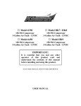
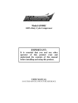
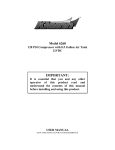
INSTALLATION AND USER MANUAL SDKIT-730 & SDKIT-734 100% Bolt-On 150 PSI Train Horn System for 2011-2015 F-250 & F-350 Super Duty P/N SDKIT-730 P/N SDKIT-734 Thank you for purchasing a Kleinn Air Horns Super Duty Train Horn System. Kleinn Train Horn Systems are the only 100% bolt-on train horn and onboard air systems for 2011-2015 Ford F-250/F-350 trucks on the market today. The main compressor and tank bracket will mount on the outside of the passenger frame rail, just below the rear door. The horns will mount just in front of the spare tire, with the trumpets pointing to the passenger side. Location of Air System Installed (Passenger Side) Horn location SDKIT 730 Primary Components: Qty. 1 SD Air System Bracket Qty. 1 SD Air Horn Bracket Qty. 1 SD Nut plate with handle Qty. 1 P/N 6350RT 3.0 Gallon Air Tank with Mounting Hardware Qty. 1 P/N 6350RC Compressor with Mounting Hardware and Remote Mount Air Intake Filter Qty. 1 P/N 730 Air Horn with Trumpet Supports, Solenoid Valve, Fittings and ½” Air Line Qty. 1 P/N INF-1 Tire Inflation Kit: 30’ Coil Hose with Quick Connect Couplers (with ¼” NPT Male Coupler & ¼” NPT Female Stud) Qty. 1 SD Wiring Harness kit with Relay SDKIT 730 Included Fittings: Qty. 1 P/N 52835 Drain Fitting Qty. 1 P/N 52175 Safety Valve Qty. 1 P/N 51414NPTL 90 degree street elbow Qty. 1 P/N 2145 Pressure Switch Qty. 1 P/N 51212 ½” Compression Fitting for ½” Air Line Qty. 1 P/N 50050 ½” NPT Plug Qty. 1 P/N JUICE -1 Kleinn Air Horn Juice™ 2ml vial Qty. 1 P/N 320 push button SDKIT 730 Included Hardware: Qty. 2 7/16” x 1-¼” inch bolts Qty. 2 7/16” flat washers Qty. 2 7/16” split lock washers Qty. 2 ½” x 1” inch bolts Qty. 2 ½” hex nuts Qty. 4 ½” flat washers Qty. 2 ½” split lock washers Qty. 2 5/16” x 1” inch bolts Qty. 2 5/16” hex nuts Qty. 4 5/16” flat washers Qty.2 5/16” split lock washers SDKIT 730 Tank Hardware- 4 each of the following: 5/16 nuts, washers, split lock washers Preparing the relay: The supplied relay should be pre-wired so that it can be installed onto the air system bracket using one of the bolts, for the rear leg of the compressor. Pin #30 connect to the supplied 12 gauge red power wire, using one of the large Yellow female crimp connectors, this will be run up to the battery. Pin # 87 connect to the compressor’s Red power wire, using one of the large Yellow female crimp connectors. (This will be finalized once the compressor and the relay are mounted to the bracket.) Pin #85 connect the 18 gauge black, about 12-18 inches in length, and will then connect to go to a chassis ground, using the small blue ring terminal and self tapping screw. (This can be common with the compressor ground). Pin #86 connect using the supplied Yellow wire coming from one of the legs on the Pressure switch. The wire from the relay to the pressure switch will be about 18 inches long and can be trimmed, and the flag connector crimped on when the tank and pressure switch are in place. The remaining yellow wire is connected to the remaining leg of the pressure switch, and will then run to the inside of the vehicle to be connected to a fused, 12v switched power source. Once these connections are made these wires can be covered using the supplied split loom. SDKIT 730 Horn Bracket Prep The SD horn bracket can be installed onto the horn, and the horn prepped, before bolting the assembly to the vehicle; as well the solenoid can be installed and wired. Pre-Installing these parts onto the horn, will allow for the easiest mounting into the vehicle. 1. Remove the center trumpet to allow for easier installation of the solenoid. 2. Apply Kleinn Air Horn Juice to the threads before installing the solenoid and fittings; be mindful of the directional arrow on the body of the solenoid, to ensure that the air flow passes through to the horn. 3. Once installed the solenoid can be wired (see diagram page 6) 4. The airline can be installed onto the compression fitting that is coming out of the solenoid. 5. Attach the SD horn bracket to the horn bar; the bracket will be positioned over the smallest trumpet, as shown in the center picture below. Preparing to install the solenoid Solenoid and fitting installed Bracket, Airline, and wires prepared SDKIT 730 Horn Bracket Install 1. Loosen the spare tire, just slightly, to allow for easier positioning of the horn and bracket. Once the horn bracket has been fully installed, the Spare can be tightened back into position. 2. The horn bracket will be installed onto the vehicle using the supplied hardware. The retaining clip holding the wire will need to be removed and this hole will be used for the horn bracket. The horn bracket will have a new hole for this clip to be installed once the bracket is in place. The larger hole at the bottom of the bracket will be secured with a ½ inch bolt. The two holes will be the top of the bracket and align and will be secured with 5/16th bolts. 3. The black ground wire form the solenoid can be trimmed to length, and the small blue ring terminal crimped on, it can then be attached to a paint free surface, with the supplied self tapping screw. 4. The purple wire and air line can be routed down the passenger side frame rail and to the area that the air system bracket will be mounted. 5. The air line will be trimmed to the back port with the ½ inch compression fitting. The purple wire will run past the bracket and into the interior of the vehicle and connect to the button. SDKIT Air System Bracket and Compressor Installation: The Air System Bracket is used to mount the air tank and air compressor to the outside passenger side frame rail of your 2011-2015 Ford F-250/F-350 Diesel truck. To prepare the bracket: 1. Attach the compressor to the Air System Bracket, using the hardware supplied in the compressor box. The compressor should be mounted to the bracket with the cylinder head facing towards the outside of the vehicle. One of the rear leg compressor bolts should be installed with the relay tab secured using the bolt. The wires for the compressor can be connected to the relay (Red wire to pin # 87) and the ground wire paired with the ground wire for the relay. 2. Once the compressor and relay are mounted, secure the Air System Bracket to the outside of the frame rail underneath the passenger side of the cab, with the compressor towards the front of the truck. The bolt to the rear of the bracket can be installed loosely, while the bracket is positioned and the 2 bolts are secured to the nut plate as it is held inside the frame. It is highly recommended that a 2nd person assist in the positioning of the bracket to start the bolt to the nut plate. Once aligned all 3 mounting points can be fully tightened. 3. The wires for the horn activation (purple) and the ignition wire for the pressure switch (yellow) can be run into the interior of the vehicle, the purple will connect to the button, for activation, and the yellow to a fused 12 volt ignition source. SDKIT-730 AIR TANK PLUMBING: Before mounting the air tank, pre-install the fittings EXACTLY as in the description below. Apply Kleinn Air Horn Juice™ sealant to the threads of fittings. Tighten one-half turn past snug with a wrench. Never over-tighten fittings. Brass threads can be stripped or broken in steel ports. The ends of the tank each have a ½ inch bung, in the rear of the tank, it will have the air line out to the horn, and the front will have a plug. The ¼ NPT bungs at the rear of the tank will be for the quick connect coupler, and the ¼ NPT at the front end of the tank will be the inlet for the compressor. The bung between the mounting feet will have the safety valve (which will protrude slightly through the hole in the bracket). The bung opposite the mounting feet will be the bottom once mounted to the bracket, and will have the drain fitting installed. The remaining port on the side will use the 90 degree adaptor and accept the pressure switch. 1. After all fittings have been installed, position the tank on the bracket studs and use the supplied 5/16” washers, lock washer, and nuts to secure the air tank to the bracket. 2. Connect the leader hose with check valve from the compressor to the port on the front of the air tank. Apply Kleinn Air Horn Juice™ to the threads, gently tighten until its snug, and then give an additional ¼ turn. DO NOT OVER-TIGHTEN THE CHECK VALVE. 3. Press one blue flag connector from the wiring harness onto each post of your pressure switch. With the connections made, slide the pressure switch rubber boot over pressure switch terminal end to seal the pressure switch. 4. Using the hardware and fittings supplied in the compressor box, attach the remote air intake line to the front of the compressor. Route the intake air line AND the red power wire from the wiring harness together up over the wheel well into the engine compartment. A good location for mounting the remote air intake filter is on the passenger side firewall close to the hood hinge. The red power wire should continue to run along and over the fender well towards the battery for connection later. SDKIT 730 Electrical and Air Connections 1. Route the air line to the compression fitting on the inlet of the solenoid valve – making sure that it is not near the exhaust or any moving parts. Attach the air line to the compression fitting on the solenoid. 2. Use zip ties to secure the loom holding the purple wire to the air line from where it exits the air tank, all the way back to the air horn. 3. Remove the single screw that holds black plastic protective housing from the solenoid and insert the end of purple wire into the round port on the housing. Trim the purple wire to length, then attach it and a ground wire to the solenoid as shown below. SDKIT 730 Wiring 1. Locate the red power wire from pin #30 of the relay and run to the battery area. Install supplied fuse holder on the end of this power wire by cutting the loop in the fuse holder and connecting a Ring terminal to one end. The ring terminal will be connected to the positive terminal of the battery. Install the 30-amp fuse provided after all other electrical connections are made. 2. Route to the inside of the cab, usually to the steering column area and connect the yellow wire to a 12volt, switched (turns on/off with key) power source. 3. Find a suitable location for the pushbutton and drill a 3/4” hole. Run the purple wire from behind and through the hole along with the supplied section of 18 gauge red wire. Slide the pushbutton retaining nut over both wires, then connect the purple to one terminal of the pushbutton and the red to the other terminal. Install the pushbutton into the hole and tighten the nut. 4. Route the 18 gauge red wire to a fused power source and connect. 5. Insert the 30-amp fuse into the fuse holder at the battery, start engine and test the compressor system by running the compressor to build up pressure in the air tank. 6. Once air pressure reaches the preset cut out pressure of your pressure switch, the compressor will shut off. Inspect all air line connections for leaks with soap and water solution sprayed directly onto fittings. If a leak is found: remove, re-seal and reinstall fittings as needed. Compressor Operation Always operate the compressor at or below its MAXIMUM PRESSURE RATING. Operation exceeding maximum pressure will damage the air compressor. 1. Your air compressor is equipped with an automatic thermal overload protection circuit, designed to protect the air compressor from overheating and causing permanent damage. The automatic thermal overload protector will automatically reset after about 30 minutes. 2. To prevent discharge of your vehicle’s battery and for best performance, keep the vehicle’s engine running while using the air compressor. System Maintenance & Repairs 1. You should occasionally check electrical and fitting connections if the system runs continuously or turns on unexpectedly. You may have leaks or poor electrical connections. 2. Periodically drain moisture from the air tank using the drain cock installed at the bottom of the tank. Failure to do so will result in decreased tank life. 3. Periodically check all hardware and tighten as needed. 4. Clean and/or replace the air compressor air filter element periodically. Replacement frequency depends on the operating frequency and conditions of the operating environment. 5. Never lubricate or add any liquids to this oil-less air compressor.