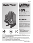
1
M2i-IOM-6
200i
Cast iron condensing boiler
Boiler manual
Installation and operation
instructions
Also read and follow:
200i Control manual
200i Vent/Air manual
This manual is intended only for use by a qualified heating installer/technician. Read and follow this manual, all supplements and related
instructional information provided with the boiler. Install, start and service the boiler only in the sequence and methods given in these
instructions. Failure to do so can result in severe personal injury, death or substantial property damage.
Do not use the boiler during construction. Construction dust and particulate, particularly drywall dust, will cause contamination of
the burner, resulting in possible severe personal injury, death or substantial property damage. The boiler can only be operated with a dustfree air supply. Follow the instruction manual procedures to duct air to the boiler air intake. If the boiler has been contaminated by operation
with contaminated air, follow the instruction manual guidelines to clean, repair or replace the boiler if necessary.
Affix these instructions near to the boiler/water heater. Instruct the building owner to retain the instructions for future use by a qualified
service technician, and to follow all guidelines in the User’s Information Manual.
P/N 42-9470 1/12 Copyright 2012 Mestek, Inc.
Cast iron condensing boiler — Installation and operation manual
The Mestek 200 i condensing cast iron boiler
Operation
Overview
The 200i is a cast iron boiler designed and constructed to allow full condensing operation. The illustration at left shows how the boiler is heated with a down-fired premix gas burner mounted above the heat
exchanger. The 200i blower pulls gas and air through a venturi assembly and pushes the mixture into the
burner. The power of the blower forces the flue products through the heat exchanger and out the vent.
Boiler operation is controlled with the 200i electronic control. The control modulates boiler firing rate
based on system demand, allowing input as low as 20% of maximum (5:1 turndown). Combined with
the indoor or outdoor reset option of the 200i control, this allows maximum possible condensing mode
operation, with combustion efficiency up to 98%.
Cast iron heat exchanger
The 200i cast iron heat exchanger uses Mestek’s graphite port seals and ground joint fit-up between sections
for maximum flexibility and resistance to thermal expansion. The heat exchanger provides maximum
heat transfer with its counterflow design and flow-controlling baffle assembly.
Premix burner
Premix means the air and gas are mixed before they enter the burner. The mixing of gas and air in the
blower and piping ahead of the burner causes a uniform gas/air mix in the burner, providing reliable operation with low excess air. The result is exceptional combustion efficiency.
The burner consists of a high-temperature stainless mesh secured to a stainless steel distributor plate. The
design causes uniform flame across the entire surface of the burner and the ability to operate at very low
firing rates. The flame is ignited with direct-spark electrodes and an electronic ignition control. Flame is
proven using a flame rod (flame rectification sensing).
Because of its low excess air operation and controlled combustion, the burner also provides low NOX
emissions and quiet operation.
Gas valve, blower and venturi
Most gas valves regulate at a positive pressure downstream of the valve (typically 3½ inches water column). But the 200i gas valve regulates to ZERO pressure downstream. This is called a “zero governor”
valve. The advantage is that gas will only flow if something lowers the pressure downstream of the valve
below zero. That is just what happens when the blower pulls air through the venturi. As the air speeds up
to pass through the narrow throat of the venturi, a vacuum forms in the throat. The more air that flows
through the throat, the greater the vacuum.
The gas valve raises the negative pressure in the venturi to zero by letting gas flow. The lower the pressure in
the venturi throat, the more gas will that will flow. So gas flow automatically adapts to air flow, ensuring
consistent gas/air mix throughout the boiler’s modulating range. Thus, the 200i SmartCycleTM electronic
control regulates the blower speed to control boiler firing rate.
200
i
schematic
flow diagram
2
200i SmartCycleTM control
The 200i SmartCycleTM electronic control consists of a microprocessor-based module and a keypad/
display unit for user interface. The control regulates boiler water temperature by adjusting boiler firing
rate (by varying the blower speed). The control considers how fast the temperature changes and how the
temperature varies over time to establish the best firing rate to meet demand. Options include an outdoor
sensor for outdoor reset operation and an indoor reset option. (Indoor reset monitors up to 8 zone thermostats and determines a maximum firing rate needed to meet the demand. This keeps the boiler at the
highest possible efficiency.) In addition, the control can be set for multiple boiler operation, either standalone or utilizing Mestek’s on-board SmartCycleTM technology. The control also automatically cycles the
factory-installed postpurge circulator to equalize residual heat in the boiler after firing.
P/N 42-9470 1/12 Copyright 2012 Mestek, Inc.
Cast iron condensing boiler — Installation and operation manual
The Mestek 200 i condensing cast iron boiler
Components
1.
Gas valve
2.
Pressure/temperature gauge
3.
Jacket
4.
Cast iron section assembly
5.
Inlet air filter access panel
6.
Blower
7.
200i SmartCycleTM control
with keypad and display
8.
Venturi assembly
9.
Pressure switches (blocked
flue and blocked air inlet)
10. Control connection board
11. Electrical box (power and
control entrances)
12. Water return connection
13. Air inlet sleeve
14. Relief valve
15. Relief valve piping
(by installer)
16. Water supply connection
17. Fenwal ignition module
18. Ignition electrodes/flame
rod assembly
19. Control transformer
(120/24 VAC)
20. Postpurge circulator,
factory-installed and piped
21. Vent connection sleeve
(with flue gas sampling port)
22. Condensate tubing connection
23. Upper section cover and
premix burner
24. Gas connection, ½” NPT
200
i
components
P/N 42-9470 1/12 Copyright 2012 Mestek, Inc.
3
Cast iron condensing boiler — Installation and operation manual
Contents
1
2
3
4
5
6
7
8
9
10
11
12
13
14
15
16
Read before beginning the installation . . . . 5
Boiler ratings and specifications . . . . . . . . . 6
Installation site preparation . . . . . . . . . . . 7
Hazard icons
You will find the following icons
throughout this manual.
(English/French)
Prepare the boiler . . . . . . . . . . . . . . . . . 10
Water piping . . . . . . . . . . . . . . . . . . . . 11
Gas piping . . . . . . . . . . . . . . . . . . . . . . 18
The WARNING icon indicates
a hazard that can cause severe
personal injury, death or
substantial property damage.
Wiring a single boiler . . . . . . . . . . . . . . . 20
Control setup . . . . . . . . . . . . . . . . . . . . 25
Vent piping (and air piping when used) . . . 28
The CAUTION icon indicates a
hazard that will or can cause minor
personal or property damage.
Condensate drain line . . . . . . . . . . . . . . 29
Fill and test the system . . . . . . . . . . . . . . 30
The NOTICE icon calls out special
instructions that are important, but
are not related to hazards.
Starting the boiler . . . . . . . . . . . . . . . . . 32
Annual start-up . . . . . . . . . . . . . . . . . . 41
Other manuals
Maintenance . . . . . . . . . . . . . . . . . . . . 42
Replacement parts . . . . . . . . . . . . . . . . 46
Appendix A — suggested wiring . . . . . . . 48
Customer service and technical support
Please direct all questions to your Mestek distributor or contact
the Mestek Customer Service Department at:
260 North Elm Street
Westfield, MA 01085
Phone (413) 568-9571
Always include the model and serial numbers from the rating
plate of the boiler in question.
Claims for damage or missing components must be filed immediately against the transportation company by the consignee.
4
You must read and follow this
manual, the 200i Vent/Air
manual, the 200i Control manual
and all additional materials
supplied with the boiler. Failure
to do so can result in severe
personal injury, death or substantial
property damage.
Start-up/service history
Before leaving the installation site
after start or service, fill out the
Start-up/service history information
on the back page.
P/N 42-9470 1/12 Copyright 2012 Mestek, Inc.
Cast iron condensing boiler — Installation and operation manual
1
Read before beginning the installation
Codes and standards
Before placing the boiler . . .
Boiler compliances
Verify boiler rating and gas supply
The 200i has been design certified by CSA for
use with natural and propane gas under the latest
revision of ANSI-Z21.13/CSA 4.9, Gas-Fired
Low Pressure Steam and Hot Water Boilers
and CAN1-3.1, Industrial and Commercial
Gas Fired Packaged Boilers. Each unit has been
constructed and hydrostatically tested for a
maximum working pressure of 100 psi (700
kPa), in accordance with Section IV of the
A.S.M.E. Boiler and Pressure Vessel Code.
Code compliances
All aspects of the boiler installation must
conform to the requirements of the authority
having jurisdiction, or, in the absence of such
requirements, to the National Fuel Gas Code,
ANSI Z223.1/NFPA 54-latest revision. Where
required by the authority having jurisdiction, the
installation must conform to the Standard for
Controls and Safety Devices for Automatically
Fired Boilers, ANSI/ASME CSD-1.
In Canada, the installation must be in accordance
with the requirements of CSA B149.1 or .2,
Installation Code for Gas Burning Appliances
and Equipment.
Commonwealth
of Massachusetts
If installing a 200i boiler in the Commonwealth
of Massachusetts, you MUST FOLLOW the
additional instructions contained in Mestek’s
instruction sheet, MA CODE. If you don’t have
a copy, call your Mestek dealer or Mestek.
When installed in the Commonwealth of
Massachusetts, ensure the following:
• The boiler must be installed by a licensed
plumber or gas fitter.
• When antifreeze is used in the system, install
an approved pressure back-flow preventer.
• Per DOE mandate, the 200i operator
control incorporates an automatic means
(outdoor/indoor air reset) of adjusting the
boiler water temperature for hot water
heating. The boiler must not operate without
the automatic means enabled.
IMPORTANT
In accordance with Section 325 (f) (3) of the Energy Policy
and Conservation Act, this boiler is equipped with a feature
that saves energy by reducing the boiler water temperature as
the heating load decreases. This feature is equipped with an
override which is provided primarily to permit the use of an
external energy management system that serves the same
function.
THIS OVERRIDE MUST NOT BE USED UNLESS AT
LEAST ONE OF THE FOLLOWING CONDITIONS
IS TRUE:
• An external energy management system is installed that
reduces the boiler water temperature as the heating load
decreases.
• This boiler is not used for any space heating .
• This boiler is part of a modular or multiple boiler system
having a total input of 300,000 BTU/hr or greater.
• This boiler is equipped with a tankless coil.
P/N 42-9470 1/12 Copyright 2012 Mestek, Inc.
•
•
Before installing the 200i boiler, check the rating plate to ensure that the unit has been sized
properly for the job.
Ensure that the boiler is set up for the type of gas available at the installation site.
Verify location is suitable
•
•
•
•
Ensure the availability of an adequate electrical supply, uncontaminated air for combustion, and
that vent (and air) piping can be correctly installed.
Ensure the boiler can be connected to system water piping and gas supply.
The boiler must not be exposed to dripping or spraying water or to rain.
If replacing an existing boiler, find out what caused the boiler to fail before installing a new boiler.
Correct the problems that led to failure, or the failure may happen to the new boiler.
Do not install or operate the boiler, or leave an installation, without complying with
all of the following, and with all information supplied in the boiler manuals.
Should overheating occur
•
Do not shut off power to the circulators if the boiler should overheat or the gas supply fail
to shut off. Instead, shut off gas supply to the boiler with a manual valve in the gas supply
line.
When servicing or operating the boiler
•
•
•
•
•
Disconnect electrical power when servicing the boiler to avoid potential for electrical
shock.
Allow the boiler, components and water to cool before attempting to remove or handle
boiler parts.
Do not add cold water to the boiler if it is hot. Allow the boiler to cool completely before
introducing cold water.
Do not operate the boiler if any part has been under water.
Follow the guidelines in the Maintenance section for dealing with fiberglass and ceramic
fiber materials.
You must have the following equipment
•
•
•
•
•
Electric multimeter
• Ammeter
Surface temperature gauge
• Metric Allen wrenches
Pressure differential gauge or included DP manometer
(3) Gas pressure meters: Two @ 0 – 14 inches WC; One @ 0 – 5 psi
Combustion analyzer — You must use a combustion analyzer and follow all instructions
in this manual to correctly start-up the boiler. As prescribed in this manual, the O2 levels
must be between 5% and 7%. Throughout all firing rate conditions, the burner surface
must never show red areas. Follow manual procedures to correct this condition.
Boiler water
•
•
•
•
•
You must thoroughly flush the system, with the boiler isolated from the system, to remove
sediment. Existing systems, in particular, often contain large amounts of iron sediment.
Excess suspended solids in the water can lead to premature boiler failure.
High efficiency equipment requires suitable water for reliable operation. Follow the ASME
recommendation for water treatment on hydronic applications that have dissolved solids
greater than 200 parts per million. Fill water must be softened if the solids concentration
is higher than this. See additional guidelines in this manual.
Do not allow the boiler to operate with frequent introduction of make-up water. Correct
all problems causing leaks, relief valve weeping, or other factors that could cause fresh
water to be added.
Do not use automotive anti-freeze in the boiler waterways. If the use of antifreeze is
necessary, an anti-freeze specifically formulated for hydronic heating systems must be
used or damage to the boiler may occur, voiding the warranty.
On applications that use antifreeze or other low conductivity fluid in the water, provide
for increased water flow or ensure proper temperature rise.
Train the user
•
Before leaving, review the User’s Information Manual with the boiler user/homeowner,
including the required maintenance to be performed by the user, the need for annual startup/maintenance by a qualified technician, the avoidance of combustion air blockage or
contamination, and never bringing or storing flammable products into the boiler area.
5
Cast iron condensing boiler — Installation and operation manual
2
Boiler ratings and specifications
Boiler model
AFUE (DOE seasonal efficiency)
Units
200i
Notes
%
92.7
1
CSA Input (Max)
Btuh
Kw
200,000
58.6
2
CSA Input (Min)
Btuh
Kw
40,000
11.7
2
Maximum allowable working pressure
PSIG
kPa
100
700
Water supply and return connections
Inches, NPT
1¼
Boiler water volume
Gallons
Liters
4.75
18.0
Shipping weight
Pounds
Kg
540
245
Operating weight
Pounds
Kg
510
231
Fuels
Natural gas or propane
Gas connection size
Inches, NPT
½
Gas supply pressure, minimum
Inches WC
mm WC
3
102
Gas supply pressure, maximum
Inches WC
mm WC
14
356
Inches
mm
3
76.2
Vent connection size
Vent options
Direct Vent or Category IV only
(pressurized vent, condensing)
Combustion air options
Air from boiler room or
ducted to boiler from outside
Combustion air adapter size
Inches
mm
3
3
76.2
Electrical requirements
Voltage
120 vac/60 hz/1-phase
Current draw (120-volt power line)
Amperes
Thermostat anticipator setting
Amperes
2.75
0
TM
5
Operating control
Mestek SmartCycle control
4
Control operation options
Stand-alone
SmartCycleTM
BMS (boiler management system)
4
Control methods
Heat demand (SmartCycle or stand-alone)
On/Off
BMS (4-20 ma input)
Staging
RS485 digital communication
4
Notes
1
2
3
4
5
6
DOE Heating capacity is based on standard tests specified by the United States Department of Energy.
All capacity ratings above are based on sea level. Input adjustments allow setting the high fire input and may compensate for moderate altitudes.
For higher altitudes the maximum boiler input will be derated slightly.
The gas valve is capable of operating with natural gas or LP. See instructions in this manual to adjust for the specific fuel used.
For additional information, refer to the 200i Control manual.
Thermostat anticipator setting is for a single thermostat connected to a single 200i boiler. Also jumper from the Heat Demand terminals to the
IAR1 terminals on the connection board. See the 200i Control manual for details.
P/N 42-9470 1/12 Copyright 2012 Mestek, Inc.
Cast iron condensing boiler — Installation and operation manual
3
Installation site preparation
Boiler location requirements
•
Buildings will require the installation of a fresh air duct or
other means of providing make-up air if the intake air option isn’t used. Any building utilizing other gas burning appliances, a fireplace, wood stove or any type of exhaust fan
must be checked for adequate combustion air when all of
these devices are in operation at one time. Sizing of an outside air duct must be done to meet the requirements of all
such devices.
•
The boiler must be supplied with combustion air in accordance with Section 5.3, “Air for Combustion and Ventilation,” of the latest revision of the National Fuel Gas
Code, ANSI Z223.1/NFPA 54 and all applicable local
building codes. Canadian installations must comply with
CSA B149.1 or .2 Installation Code for Gas Burning Appliances and Equipment, or applicable provisions of the local
building codes.
Do not install the boiler unless the location
meets all of the requirements in this box.
Failure to comply could result in severe personal
injury, death or substantial property damage.
Indoor installation only
•
Do not install the boiler outside or in an area that would expose the boiler or its gas or electrical components to rain or
dripping or spraying water.
•
Do not install the boiler in a location that would subject the
boiler to freezing. Where freeze protection is needed, follow
the guidelines in this manual.
Flooring
Negative room pressure
•
The boiler can be installed on combustible flooring, but
must not be installed on carpeting.
•
•
The floor must be structurally sound and capable of supporting the weight of the boiler.
•
The boiler must be leveled front to back and side to side.
Use metal shims if necessary.
Combustion air contamination
•
Combustion air contaminated with fluorocarbons or other
halogenated compounds such as cleaning solvents and refrigerants will result in the formation of acids in the combustion chamber. These acids will cause premature failure
of the boiler.
•
Construction dust: If the boiler is operated while the
Accessibility
•
Jacket parts will have to be removed for some service procedures. Ensure that the location provides a reasonable means
for service and operation of the boiler.
building is under construction it must be protected from
wood, concrete, sheet rock and other types of dust. Failure
to properly protect the boiler from construction dust will
damage the boiler.
System piping, fuel and electrical supply
•
The boiler must be located such that piping for water, gas,
vent and air can reasonable be connected.
•
There must be a reasonable means of providing electrical
supply to the boiler.
•
If the boiler has been operated with contaminated air, it
must be thoroughly inspected. Where possible, boiler components must be cleaned, following instructions provided
in this manual and/or supplementary instructions from
Mestek. Where cleaning is not possible, the boiler may have
to be replaced.
•
Never store combustible materials, gasoline or any product
containing flammable vapors or liquids in the vicinity of the
boiler.
Adjacent construction
•
Locate the boiler in an area that will prevent water damage
to adjacent construction should a leak occur or during routine maintenance.
Combustion air
•
•
Do not place the boiler in a location that would restrict
the flow of combustion air into the air intake or subject the
boiler to a negative air pressure in the space when using air
from the boiler room.
Provide required combustion air openings to the boiler
room and the building (when required) when using air
from the boiler room for combustion (see page 8). If air is
piped to the boiler air intake connection, combustion air
openings are not required unless other appliances share the
same room.
P/N 42-9470 1/12 Copyright 2012 Mestek, Inc.
Never operate the boiler in an environment subjected to a
negative pressure unless it is Direct Vented. Failure to comply with this warning can result in excessive levels of carbon
monoxide.
Clearances
•
All installation must provide the minimum clearances to
combustible materials given on page 8.
•
The installation should provide the minimum service clearances given on page 8 when possible. If these clearances
cannot be met, then:
•
Ensure that boiler components can be accessed for
operation/start-up/maintenance as required in the
200i manuals.
7
Cast iron condensing boiler — Installation and operation manual
3
Installation site preparation (continued)
Clearance requirements
Figure 1
Clearance to combustibles references
Figure 2
Service/operation clearance references
Clearances to combustible surfaces
All installations must provide the minimum clearances to combustible
materials and surfaces given in Table 1. Failure to comply could result
in a fire hazard, causing severe personal injury, death or substantial
property damage.
Table 1
Minimum clearances to combustible materials/surfaces for ALL
installations (Figure 1)
From:
Top
Back
Left side
Right side
Front
Rear
Vent piping
System water piping
Inches
Millimeters
6
6
6
6
6
6
2
1
153
153
153
153
153
153
51
25.4
If the boiler is located in a closed room, the room must be provided with
ventilation openings even if air is ducted to the boiler. See Figure 1. Size
the openings with a free area no less than 1 square inch per BTUH input
of all 200i boilers in the room.
EXCEPTION: Ventilation openings are not required if the boiler room
provides at least the minimum SERVICE/OPERATION clearances
given in Table 2. Failure to provide adequate ventilation could result in
overheating of the boiler components or the room, potentially causing
severe personal injury, death or substantial property damage.
Clearances for service and operation
The installation must provide reasonable access and clearance for service
and operation of the boiler. Table 2 gives recommended minimum
clearances for service and operation. The boiler may be installed in a
space that does not provide these recommended clearances provided
it is accessible for the service and operation procedures required in the
200i manuals.
Flame observation port — The flame observation port on the LEFT
side of the boiler must be accessible to view the combustion chamber
during boiler start-up. Make sure that the installation allows serviceman
access to the left side for this purpose.
Table 2
Recommended minimum clearances for service/operation
(Figure 2)
From:
Inches
Millimeters
Top
Back
Left side
Right side
Front
24
24
24
24
36
610
610
610
610
914
Rear
18
457
8
P/N 42-9470 1/12 Copyright 2012 Mestek, Inc.
Cast iron condensing boiler — Installation and operation manual
3
Installation site preparation (continued)
Figure 3
Combustion air requirements
Air ducted to boiler air intake
If air is ducted from outside to the boiler air intake, follow instructions in the
200i Vent/Air manual to size and install the air piping.
Air opening options for combustion air
drawn from boiler room
If other appliances are located in the same room
as the boiler, increase the size of air openings
to provide the free area required for the other
appliances in addition to the air required for the
200i boiler(s).
If the boiler is located in a small room (clearances less than the recommended
SERVICE/OPERATION clearances given in Figure 2):
• No other appliances in the room — Provide two ventilation openings
through one of the enclosure walls. Each opening must be sized for a free
area of at least 1 square inch per 1,000 BTUH input of the 200i boilers in
the room. One opening must be within 12 inches of the ceiling, the other
within 12 inches of the floor.
• Other appliances in the same room — The room must have combustion
air openings sized for the other appliances. Increase the free area of the air
openings by one square inch per 1,000 BTUH of the 200i boilers located
in the room.
Air from boiler room
When the boiler draws combustion air from the boiler room:
• If the room volume is at least 50 cubic feet per BTUH of the combined
input of all appliances in the room, no special openings are needed
UNLESS the building is of tight construction (see definition). If the building is
of tight construction, provide openings to the building in accordance
with all applicable codes.
• If the boiler is in a space smaller than 50 cubic feet volume per BTUH input,
provide air openings using one of the methods in Figure 3.
Definitions
Free area — Louvers or grilles reduce the area of an opening. Free area is the
area remaining with the louver or grille in place. If the free area of a louver is
unknown, use the following:
• Metal louver — Multiply required free area of the opening times 1.7 to
determine actual area of the required opening.
• Wood louver — Multiply required free area of the opening times 5 to determine actual area of the required opening.
Tight construction — When a building is extensively sealed to prevent air
infiltration, it cannot provide enough air for combustion unless openings are
provided to the outside. The National Fuel Gas Code defines such buildings as
having all of the following:
• Walls and ceilings exposed to the outside atmosphere have a continuous
water vapor retarder with a rating of 1 perm or less with openings gasketed.
• Weather-stripping has been added on openable windows and doors.
• Caulking or sealants are applied to areas such as joints around windows
and door frames, between sole plates and floors, between wall-ceiling
joints, between wall panels, at penetrations for plumbing, electrical, and
gas lines, and in other openings.
Conversion factors
In2/1,000 BTUH to cm2/kw — Multiply In2/1,000 BTUH times 22
In2/2,000 BTUH to cm2/kw — Multiply In2/2,000 BTUH times 11
In2/3,000 BTUH to cm2/kw — Multiply In2/3,000 BTUH times 7.4
In2/4,000 BTUH to cm2/kw — Multiply In2/4,000 BTUH times 5.5
P/N 42-9470 1/12 Copyright 2012 Mestek, Inc.
Upper openings (U) must be within 12 inches of the ceiling. Lower
openings (L) must be within 12 inches of the floor.
Option 1 — air openings through interior wall
When air is supplied to the boiler room through openings in an interior
wall (air supply from inside the building), size each opening to provide
minimum free area of:
1 in2 per 1,000 BTUH of all 200i boilers in the room.
Option 2 — air openings through outside wall
When air is supplied to the boiler room through openings in an outside
wall (air supply from outside the building), size each opening to provide
minimum free area of:
1 in2 per 4,000 BTUH of all 200i boilers in the room.
Option 3 — horizontal ducts to outside wall
When air is supplied to the boiler room through horizontal ducts to an
outside wall (air supply from outside the building), size each opening
to provide minimum free area of:
1 in2 per 3,000 BTUH of all 200i boilers in the room.
Option 4 — openings to attic/crawl space
Air openings can be connected to a ventilated attic or crawl space. The
upper opening must be to the attic. The lower opening can be a vertical
duct from the attic or an opening in the floor from the crawl space. Size
each opening to provide minimum free area of:
1 in2 per 3,000 BTUH of all 200i boilers in the room.
Option 5 — single opening (not shown)
A single opening directly connected to the outdoors through a wall or
a vertical or horizontal duct can be used if the installation provides the
clearances of Figure 2, and the top of the opening is within 12 inches of
the ceiling. Size the opening to provide minimum free area of:
1 in2 per 3,000 BTUH of all 200i boilers in the room.
9
Cast iron condensing boiler — Installation and operation manual
4
Prepare the boiler
Remove the boiler from the crate
Cold weather handling — The boiler jacket
includes plastic parts. If the boiler has been in a cold
environment (below 0 °F), allow the boiler to warm
to room temperature before handling.
Do not drop the boiler or allow the jacket to bump
against the floor or wall when handling.
1. Remove the crate from the skid. But leave the boiler on the
skid to move the boiler near its location.
2. Inspect the boiler thoroughly for any possible damage that
may have occurred in shipping or handling.
3. Slide the boiler off of the skid into position.
4. Use a spirit level to check whether the boiler sides and front
are vertically plumb. If not, slide metal shims under the base
until the boiler is level.
Piping guidelines:
•
•
•
•
•
•
•
Install the relief valve
Check relief valve pressure setting
All installations must be installed by a qualified technician
in accordance with the latest revision of the ANSI/ASME
Boiler and Pressure Vessel Code, Section IV.
Where required, the installation must comply with ANSI/
ASME CSD-1, Standard for Controls and Safety Devices
for Automatically Fired Boilers.
All applicable local codes and ordinances must also be followed.
A minimum clearance of 1 inch (25 mm) must be maintained between heating system pipes and all combustible
construction.
All heating system piping must be supported by suitable
hangers — not by the boiler.
The thermal expansion of the system must be considered
when supporting the system.
A minimum system pressure of 12 psig (84 kPa) must be
maintained.
Figure 4
Relief valve piping
Inspect the boiler relief valve before installing to ensure it is set
at the pressure required for the system. You should also verify
that all water system components are rated for at least the pressure setting of the relief valve to avoid component damage due
to excess pressure.
The boiler maximum allowable working pressure
is 100 psig (700 kPa). The relief valve must never
have a setting greater than 100 psig. Using a higher
pressure relief valve could result in an explosion,
causing possible severe personal injury, death or
substantial property damage.
Connecting the relief valve
Connect ¾-inch NPT black iron pipe and fitting so the relief
valve as shown in Figure 4. Follow all instructions provided in
the relief valve manufacturer’s instructions and labeling.
Never install any type of valve between the boiler
and the relief valve, or in the relief discharge
piping. An explosion could occur, causing severe
personal injury, death or substantial property
damage. General piping requirements.
Boiler piping — general
Improper piping of the boiler will void the
manufacturer’s warranty, and can cause boiler
failure, resulting in possible severe personal
injury, death or substantial property damage.
Install a shut-off valve in the boiler supply and
return connections to allow isolation of the
boiler for servicing when necessary.
10
P/N 42-9470 1/12 Copyright 2012 Mestek, Inc.
Cast iron condensing boiler — Installation and operation manual
5
Water piping
Boiler piping connections
The boiler supply and return connections are shown in Figure 4.
Both connections are 1¼-inch NPT.
Size piping for the flow required. Piping connections to the
200i boiler should generally be 1¼-inch NPT.
The 200i boiler requires a continuous minimum water flow for proper
operation. The circulator for the boiler must be sized to overcome the
head loss of the boiler and the heating system in order to achieve the
required temperature rise. If the system contains hydronic antifreeze
this must be considered when sizing the pump. The temperature rise
across the boiler must never exceed 100°F (55.6°C).
Boiler pressure drop
System design
Design options
The 200i boiler works well in a single or multiple-boiler application
for any type of system. The following pages include suggested
piping diagrams for the following system options:
• Single boiler, zoning with zone valves (page 13).
• Single boiler, zoning with circulators (page 14).
• Multiple boilers, primary/secondary piping (page 15).
• Multiple boilers, parallel piping, reverse-return (page 16).
• Guidelines for chilled water systems (page 17).
All of the piping diagrams show the suggested piping for optional
indirect-fired DHW tanks. Follow the DHW tank manufacturer’s
instructions for installation and piping. Make sure to size the
DHW circulator and piping to provide the flow needed for the
required recovery capacity.
Pipe sizing
Assume a pressure drop of:
• 1.9 feet WC (0.7 meter) for a flow rate of up to 18 GPM (68 LPM).
• 7.5 feet WC (2.3 meters) for a flow rate of up to 36 GPM (136 LPM).
Maintain boiler flow rate between 2 GPM and 36 GPM (7.6 to 136 LPM).
Boiler and system circulators
See the following pages for suggested piping for 200i boilers. All circulators are supplied by the installer, except the factory-installed postpurge circulator.
Boiler circulator — the circulator that flows water through the boiler.
System circulator — the circulator that flows water through the system, but not
through the boiler.
Boiler/system circulator — a circulator that flows water through the boiler and
the system.
Circulator activation
See section 7 of this manual and the 200i Control manual for instructions on wiring
boiler and system circulators.
Generally install 1¼-inch piping in the boiler circuit. Size system
and other circuit piping based on a 20 °F temperature drop
through the zones. For water-source heat pump systems, the
primary circuit flow rate will usually be based on a 5°F temperature
drop. Such high flow systems must be piped with the boiler on
a separate loop.
The 200i SmartCycle Control provides an isolated contact to operate the boiler circulator
(or boiler/system circulator).
Piping guidelines
Additional controls
Support the piping — All piping and
components must be supported such that no loads
or stresses are applied to the boiler. Allow for thermal
expansion in the piping design and passageways.
The piping diagrams in this manual omit piping
components such as unions. Always install unions
where needed to simplify piping and improve
serviceability.
The system circulator must be activated by a relay supplied by the installer. This relay
is usually activated by the system control or thermostat.
Local codes or job specifications may require the use of additional controls, such as low
water cut-offs, flow switches, and high limit controls. Refer to the 200i Control manual
for electrical connections for auxiliary controls.
Follow the guidelines below to install typical controls in the piping.
Low water cut-off
When the boiler is installed above terminal units, or when required by applicable
codes, install a low water cut-off in the piping above the boiler. See suggested piping in
the diagrams in this section.
Circulator requirements
Use a probe-type control when possible.
Boiler postpurge circulator
Flow switch
The postpurge circulator supplied with the
200i (Figure 4), factory piped between the boiler
supply and return connections, is NOT intended
for use in the system. It must remain connected as
supplied. The postpurge circulator is only used by
the 200i for postpurge flow to remove residual heat
in the combustion zone. The postpurge circulator
includes an integral check valve to prevent by-pass
flow during operation.
P/N 42-9470 1/12 Copyright 2012 Mestek, Inc.
When a flow switch is required, install the switch in a section of the piping that will
ensure enough flow to operate the switch.
Additional high limit controls
For ASME CSD-1 or Canadian applications, or when required by applicable codes,
install an additional high limit control in the supply piping above the boiler.
Make sure the limit control is set at least 20 °F above the highest operating temperature
of the 200i boiler.
11
Cast iron condensing boiler — Installation and operation manual
5
Water piping (continued)
Expansion tank and air separation
Figure 6
Diaphragm or bladder-type expansion tank
suggested piping
Figure 7
Closed-type expansion tank suggested piping
The system must include an expansion tank to control thermal expansion. Install the
tank as close as possible to the boiler, and locate on the suction side of the system circulator. Make sure the tank is sized large enough to handle the system volume.
Figure 5
Expansion tank comparison
Diaphragm/bladder type expansion tank
Diaphragm or bladder-type expansion tanks have a membrane that separates the water
from the air in the tank. See Figure 5, left side. See Figure 6 for suggested piping.
Guidelines for diaphragm/bladder-type expansion tanks
•
•
Always remove the tank from the system before charging. This ensures the air pressure
will be accurate. Make sure the charge pressure equals the required system cold-fill
pressure (usually 12 psig).
Install an automatic air vent on top of the air separator to remove air from the system.
Closed-type expansion tank
Closed-type tanks are those that have air above the water, in direct contact with the
water. See Figure 5, right side. See Figure 7 for suggested piping.
Guidelines for closed-type expansion tanks
•
•
•
NEVER use automatic air vents in systems with closed-type tanks. The air must be
kept in the system, and returned to the tank, in order to keep the tank operating
correctly. Automatic air vents will bleed air out of the system, resulting in waterlogging of the tank, causing the boiler relief valve to weep.
Air separation is done by connecting from an in-line air separator to the bottom of
the expansion tank (Figure 7). The tank must be mounted above the air separator.
Install a tank fitting in the bottom of the tank. It allows captured air to flow into
the upper portion of the tank, facilitates filling, and reduces recirculation in the
expansion tank piping.
Cold water fill
Follow all applicable codes when connecting the cold water fill to the piping. Use a
backflow preventer where required. See suggested piping on this and the following
pages. Also consider installing a water meter on the cold water make-up line. The water
meter will show if excessive make-up water is entering the system.
12
Undersized or waterlogged expansion tanks will
cause excessive make-up water to enter the system.
This will lead to section failure due to oxygen
corrosion and lime deposits.
P/N 42-9470 1/12 Copyright 2012 Mestek, Inc.
Cast iron condensing boiler — Installation and operation manual
5
Water piping (continued)
Zoning with zone valves
DHW operation, when required
Flow balancing and control
The piping shown throughout this manual allows for domestic water heating
without flow through the heating loop(s). This is important for summertime operation of DHW tanks.
On large systems, or when using a high-head circulator, install a differential
pressure by-pass valve to limit the head applied to the zone valves.
Some systems may require balancing valves to control flow in the loops.
Figure 8
Suggested piping — single boiler — zone valve zoning — two-pipe or series loop (left), or primary/secondary piping (right)
L EGEND • • • • • • •
1
2
3
4
5
6
7
8
Make sure to incorporate flow/check valves as shown. These prevent forced
flow in idle zones.
200i boiler
Boiler circulator
System circulator
Boiler/system circulator
Indirect-fired DHW tank
(when used)
DHW circulator
Flow/check valve
Cold water fill line
P/N 42-9470 1/12 Copyright 2012 Mestek, Inc.
9
10
11
12
13
14
Expansion tank (shown with diaphragm-type —
see page 12 for piping a closed-type tank)
Expansion tank (shown with diaphragm-type —
see page 12 for piping a closed-type tank)
Air separator with automatic air vent (Replace air
vent with piping to the tank fitting on closed-type
expansion systems.)
Low water cut-off (when required)
Extra high limit (when required)
Zone valve
Zone circulator
15 Differential pressure by-pass valve — Use when highhead circulator may cause noise, erosion or valve lifting
problems when only a few zone valves are open.
16 Boiler postpurge circulator (see page 11)
17 Header sensor, required where shown
Isolation valve
Purge valve — Suggested locations allow for improved
system filling and draining and initial air elimination.
Temperature gauge
13
Cast iron condensing boiler — Installation and operation manual
5
Water piping (continued)
Zoning with circulators
DHW operation, when required
Sizing and flow control
Size circulators to provide the flow needed for the individual zones.
The piping shown throughout this manual allows for domestic water heating
without flow through the heating loop(s). This is important for summertime operation of DHW tanks.
Provide flow/check valves where shown to prevent gravity circulation or
forced flow in idle zones.
Make sure to incorporate flow/check valves as shown. These prevent forced
flow in idle zones.
Figure 9
Suggested piping — single boiler — circulator zoning — two-pipe or series loop (left), or primary/secondary piping (right)
L EGEND • • • • • • •
1
2
4
5
6
7
8
200i boiler
Boiler circulator
Boiler/system circulator
Indirect-fired DHW tank
(when used)
DHW circulator
Flow/check valve
Cold water fill line
14
9
Expansion tank (shown with diaphragm-type — see
page 12 for piping a closed-type tank) Expansion tank
(shown with diaphragm-type — see page 12 for piping
a closed-type tank)
16 Boiler postpurge circulator (see page 11)
17 Header sensor, required where shown
Isolation valve
10 Air separator with automatic air vent (Replace air vent
with piping to the tank fitting on closed-type expansion
systems.)
Purge valve — Suggested locations allow for improved
system filling and draining and initial air elimination.
11 Low water cut-off (when required)
Temperature gauge
12 Extra high limit (when required)
14 Zone circulator
P/N 42-9470 1/12 Copyright 2012 Mestek, Inc.
Cast iron condensing boiler — Installation and operation manual
5
Water piping (continued)
Multiple boilers, primary/secondary
DHW operation, when required
Sizing and flow control
Size circulators to provide the flow needed for the individual zones.
The piping shown throughout this manual allows for domestic water heating
without flow through the heating loop(s). This is important for summertime operation of DHW tanks.
Provide flow/check valves where shown to prevent gravity circulation or
forced flow in idle zones.
Make sure to incorporate flow/check valves as shown. These prevent forced
flow in idle zones.
Figure 11
Suggested piping — multiple boilers — primary/secondary piping, reverse-return boiler headers
3
Supply
to system
Return
from system
12" max
(305 mm)
17
10
8
9
7
12
11
DHW tappings
7
7
7
7
4
5
2
2
1
2
1
16
2
1
16
1
16
16
20010
L EGEND • • • • • • •
7
Flow/check valve
12 Extra high limit (when required)
8
Cold water fill line
16 Boiler postpurge circulator (see page 11)
9
Expansion tank (shown with diaphragm-type — see
page 12 for piping a closed-type tank) Expansion tank
(shown with diaphragm-type — see page 12 for piping
a closed-type tank)
17 Header sensor, required
1
200i boiler
2
Boiler circulator
3
System circulator
5
Indirect-fired DHW tank
(when used)
10 Air separator with automatic air vent (Replace air vent
with piping to the tank fitting on closed-type expansion
systems.)
6
DHW circulator
11 Low water cut-off (when required)
P/N 42-9470 1/12 Copyright 2012 Mestek, Inc.
Isolation valve
Temperature gauge
15
Cast iron condensing boiler — Installation and operation manual
5
Water piping (continued)
Multiple boilers, parallel flow
DHW operation, when required
Sizing and flow control
When heating system boilers are piped in parallel as in Figure 12, connect
the DHW tank as a zone off of the main header or install boilers dedicated
to the DHW application.
Size the boiler/system circulator to handle the flow needs of all zones. If
using variable speed control of the boiler/system circulator, ensure that the
flow never drops below the total minimum for all boilers connected. Do
not exceed the maximum flow of 50 GPM through any boiler.
Figure 12
Suggested piping — multiple boilers — parallel-flow piping, reverse-return headers
L EGEND • • • • • • •
8
Cold water fill line
9
Expansion tank (shown with diaphragm-type — see
page 12 for piping a closed-type tank) Expansion tank
(shown with diaphragm-type — see page 12 for piping
a closed-type tank)
12 Extra high limit (when required)
16 Boiler postpurge circulator (see page 11)
1
200i boiler
4
Boiler/system circulator
5
Indirect-fired DHW tank
(when used)
10 Air separator with automatic air vent (Replace air vent
with piping to the tank fitting on closed-type expansion
systems.)
Isolation valve
6
DHW circulator
11 Low water cut-off (when required)
Temperature gauge
16
17 Header sensor, required
P/N 42-9470 1/12 Copyright 2012 Mestek, Inc.
Cast iron condensing boiler — Installation and operation manual
5
Water piping (continued)
Chilled water systems
The boiler loop can be any of the designs in this manual, or per
standard engineering practices.
General
Use the balancing valve to adjust the boiler loop flow.
Provide the piping components shown in Figure 13 when
connecting a boiler to a chilled water system. The check valve
(item 4) prevents chilled water from entering the boiler loop.
Expansion tank/air control
Sizing and flow control
Size the system circulator to handle the flow needs of all zones.
If using variable speed control of the system circulator, ensure
that the flow never drops below the total minimum for all boilers connected.
Figure 13
Chilled water systems generally use closed-type expansion
tanks. DO NOT use automatic air vents in these systems. All air
must be return to the expansion tank for the system to operate
reliably.
If the boiler loop is connected to air handling units
that use chilled water, install flow control devices to
prevent gravity circulation in the boiler loop during
the cooling cycle in the air handling units.
Suggested piping — boilers connected to chilled water systems
P/N 42-9470 1/12 Copyright 2012 Mestek, Inc.
17
Cast iron condensing boiler — Installation and operation manual
6
Gas piping
Check the gas type
Item 3 — For all gas supply piping, use only clean, burr-free black iron pipe, supported
independently from the boiler gas connection.
The 200i comes from the factory ready to be piped to the gas
supply. If for any reason the boiler is not for the type of gas available at the installation site, call your Mestek representative to
resolve the problem. (See WARNING below.)
Item 4 — Install a ground-joint union in the gas line for ease of installation and servicing.
Gas supply components
Item 6 — The gas cock must be equipped with a pressure test port. This test port is
used to measure the gas supply pressure at the boiler.
Figure 14 depicts the proper way to connect the boiler to the gas
supply piping. The gas connection at the boiler is ½” NPT.
Item 1 — Install the gas line piping from the gas meter or branch
in accordance with all applicable codes. See the next page for
suggested sizing, or refer to the National Fuel Gas Code or Canadian Gas Code for recommendations.
Item 5 — Provide a sediment trap at the bottom of the vertical section of the gas supply
pipe upstream of the gas controls.
The gas line components in Figure 14 are not supplied with the boiler. They must be
supplied by the boiler installer.
Always use a wrench on the gas grain components when making gas
connections. Never over-tighten the piping components or a failure
could result, causing possible severe personal injury, death or substantial
property damage.
Item 2 — The manual shut-off valve must be installed in the
supply piping. Install 5 feet above the floor where required by
applicable codes.
Figure 14
Connecting gas supply line
Failure to adhere to the following
could result in severe personal injury, death or substantial property
damage.
Verify the gas type
Check the boiler rating plate to make sure that the boiler
is for the type of gas that will be used. If it is not, do not
connect the boiler to the gas supply.
Support the gas line
Support the gas line with hangers. DO NOT allow gas
train weight to rest on or cause bending of the boiler gas
connection fitting.
Protect the gas connection fitting
Use a 15/16 – inch open-end wrench to hold the boiler
gas connection fitting when tightening gas connection
piping to the boiler.
Never leak test with flame
Never use an open flame to test for gas leaks. Always use
an approved leak detection method.
Protect the boiler gas valve from
excessive pressure
When pressure testing system gas piping, disconnect
the gas piping from the boiler or isolate the boiler with
the manual shut-off valve if test pressure will be higher
than ½ psig (3.5 kPa).
18
1
Piping from gas supply
2
Manual gas valve with test port
(use tee-handle valve for
Massachusetts installations)
3
Piping must be clean and burr-free
black iron pipe
4
Ground-joint union
5
Drip leg with cap
6
Gas cock pressure test port
P/N 42-9470 1/12 Copyright 2012 Mestek, Inc.
Cast iron condensing boiler — Installation and operation manual
6
Gas piping (continued)
Gas piping joints
Always use a pipe sealant that is suitable for use
with LP gas. Failure to comply could result in
an explosion, causing possible severe personal
injury, death or substantial property damage.
Only use pipe dope listed for use with propane gas. Even natural
gas may contain some amount of propane.
Use pipe dope sparingly. Excessive pipe dope can block pipe
flow or foul gas train components.
Table 3
Gas flow capacity for black iron pipe
Iron
pipe
size
Pipe length, equivalent feet (length plus allowance for fittings)
10
¾”
278
20
30
40
50
60
80
Natural gas pipe flow capacity (cubic feet per hour)
190
152
130
115
105
90
Required supply pressure at boiler
Minimum gas supply pressure (natural gas or propane), both for
flowing and static conditions:
(notes 1, 2, 3)
79
64
1”
520
350
285
245
215
195
170
150
120
1050
730
590
500
440
400
350
305
250
1 ½”
1600
1100
890
760
670
610
530
460
380
(notes 2, 3)
¾”
172
118
94
81
71
65
56
49
40
1”
320
220
175
150
135
120
105
95
75
1 ¼”
650
455
365
310
275
250
220
190
155
Notes, Table 3
1
2
4 inches (102 mm) water column.
Maximum gas supply pressure (natural gas or propane), both
for flowing and static conditions:
150
1 ¼”
Propane gas pipe flow capacity (cubic feet per hour)
Gas pipe sizing
100
3
Natural gas flow capacity is based on 0.60 specific gravity. Refer to the National Fuel Gas Code, ANSI
Z223.1/NFPA 54, for other pressure drops and other specific gravity gases.
The flow rates above allow for a pressure drop of:
Natural gas — 0.30 inches water column, with gas pressure 14 inches water column or less.
Propane — 0.30 inches water column, with gas pressure 14 inches water column or less.
To determine required flow rate in cubic feet per hour for all appliances connected to the gas line:
Natural gas — Divide total Btuh by the gas Btu per cubic foot rating (typically 1,000 Btu/ft3 nominal).
Propane — Divide total Btuh by 2,500.
14 inches (356 mm) water column.
Table 4
Sizing guidelines
The sizing recommendations of Table 3 are taken from the National
Fuel Gas Code, ANSI Z223.1/NFPA 54. Propane values are based
on adjustment from propane specific gravity and pressure.
Table 3 allows for a pressure drop from the main supply regulator
to the boiler of 0.3 inches (7.6 mm) water column for natural
gas or propane.
For conditions not shown in Table 3, other pressure drops, or
natural gas with other than 0.6 specific gravity, refer to the appropriate code guidelines for sizing.
Equivalent feet of pipe for common gas line components
Iron
pipe
size
90° Elbow
Equivalent feet of pipe for each fitting
1”
Tee
Gate valve
Gas cock
(note 1)
(note 2)
(note 2)
2.6
5.2
0.6
1.5
1 1/4”
3.5
6.9
0.8
1.9
1 1/2”
4.0
8.0
0.9
2.3
2”
5.2
10.3
1.2
3.0
Notes, Table 4
1
2
Allows for flow through the branch of the tee.
Assumes valve is full open.
Equivalent length
Do not neglect the pressure drop due to pipe fittings.
Equivalent length is the sum of the actual length of piping plus
the total equivalent lengths of all fittings in the line from the
main regulator to the boiler connection. See Table 4 for equivalent lengths of common fittings and components.
Multiple appliances
If more than one appliance is supplied by the same supply pipe, the
piping must be sized based on the maximum possible demand.
Undersized gas supply piping can cause the
gas line pressure to become negative during
operation of the 200i boiler. This can cause pilot
outages and operation failures of other appliances
connected to the line, including gas ranges, water
heaters, etc. Failure to properly size the gas lines
can result in potential for severe personal injury,
death or substantial property damage.
P/N 42-9470 1/12 Copyright 2012 Mestek, Inc.
Test all gas piping for leaks
All gas piping, components and connections must be leak tested
before putting the boiler in operation. Isolate the boiler from the gas
supply piping if testing with pressure greater than 14 inches (12.7 mm)
pressure. Failure to do so could result in severe personal injury, death or
substantial property damage.
Check all gas piping components and joints for
leaks. Use either a soap suds mixture, a gas leak
detector or other suitable means.
After testing the system gas piping, remove the
gas valve cover plate on the left side of the boiler
(see illustration at right). Inspect and leak test
around the interior gas line and gas valve. Replace
the cover after completing the gas connection
inspection and testing.
19
Cast iron condensing boiler — Installation and operation manual
7
Wiring a single boiler
Figure 15
Electrical connection board (see item 10,
page 3 for location — Also see the wiring
summary illustrations on the next pages)
Figure 16
120VAC power service terminals on electrical connection board — See Figure 15 for
location of the power terminal strip
Electrical shock hazard — Disconnect
all electrical power sources to the
boiler before making any electrical
connections.
Label all wires prior to disconnection
when servicing controls. Wiring errors
can cause improper and dangerous
operation! Verify proper operation after
servicing.
Au moment de l’entretien des commandes, étiquetez tous les fils avant de
les débrancher. Des erreurs de câblage
peuvent entraîner un fonctionnement
inadéquat et dangereux. S’assurer que
l’appareil fonctionne adéquatement une
fois l’entretirn terminé.
Failure to comply with the above could
result in severe personal injury, death or
substantial property damage.
The electrical connections to this boiler
must be made in accordance with all
applicable local codes and the latest
revision of the National Electrical Code,
ANSI /NFPA-70. Installation should
also conform to CSA C22.1 Canadian
Electrical Code Part I if installed in
Canada. Install a separate 120 volt 15
amp circuit for the boiler. A properly
rated shut-off switch should be located at
the boiler. The boiler must be grounded
in accordance with the authority having
jurisdiction, or if none, the latest revision
of the National Electrical Code, ANSI/
NFPA-70.
Line voltage field wiring of any controls
or other devices must use copper
conductors with a minimum size of #14
awg. Use appropriate wiring materials
for units installed outdoors.
General
•
The wiring and control information in the Boiler manual is
targeted at single-boiler, stand-alone installations. For multiple
boilers and advanced options, see the 200i Control manual.
•
See Figures 20 and 21 for a wiring summary. See the Control
manual for content not covered in this manual.
Power supply (120 VAC)
20
•
See Figures 15 and 16.
•
Connect minimum 14 awg copper wire to the power
connection as shown in Figure 16.
•
Install a fused service switch, mounted and installed in
accordance with all applicable codes.
P/N 42-9470 1/12 Copyright 2012 Mestek, Inc.
Cast iron condensing boiler — Installation and operation manual
7
Wiring single boiler (continued)
Circulator wiring
Postpurge circulator
•
•
Figure 19
Circulator wiring terminal strip (see Figure 15
for location) — Also see the wiring summary
illustrations on the next pages)
The circulator shipped installed with the boiler
cannot be used for system circulation. It must be used
as supplied from the factory. It circulates water after the boiler
stops firing to prevent potential damage from heat pocketing
in the top of the heat exchanger.
The postpurge circulator is factory-piped and pre-wired. Do
not change the usage, the wiring, the location or the piping.
Boiler circulator
•
•
•
See section 5 of this manual for circulator piping.
Figure 19 shows wiring of the Boiler circulator (or boiler/
system circulator) to the terminal strip of the 200i electrical
connection board.
DO NOT directly connect a circulator with a motor larger
than 1/4 hp. For larger motors, install a circulator relay or
motor contactor . Figures 17 and 18 show the correct ways
to install the boiler circulator using a relay or motor starter.
Figure 17
Wiring the boiler circulator using a circulator
relay (required for motors over 1/4 hp)
Figure 18
Wiring the boiler circulator using a relay or
starter (required for motors over 1/4 hp)
P/N 42-9470 1/12 Copyright 2012 Mestek, Inc.
21
Cast iron condensing boiler — Installation and operation manual
7
Wiring single boiler (continued)
Sensor wiring
No sensor wiring is necessary unless:
•
•
•
Figure 20
Indoor Air Reset wiring to IAR terminals with
4-wire zone valves and no zone controller
(see Figure 21a for terminal block 6 location).
Outdoor reset application — To operate with outdoor reset, purchase and install
an outdoor sensor. Mount the sensor such that it is shielded from direct sunlight if
possible and not likely to be covered by snow drifts or debris. Connect the outdoor
sensor leads to the electrical connection board as shown in Figure 21b, page 24.
Header sensor application — As shown in the piping diagrams in this manual,
a header sensor is needed if the boiler supply temperature may be different from
the header temperature. If required, purchase and install a header sensor in an immersion well. Locate the sensor where it will accurately sense the system water
supply temperature. Connect the sensor leads to the electrical connection board
as shown in Figure 21b, page 24.
Return water temperature sensor — The return water temperature sensor
is optional, only needed if you want to automatically control the boiler postpurge
pump cycle time. To use the return water temperature sensor, purchase and install
the sensor in a well in the boiler return piping. Connect the sensor leads to the
electrical connection board as shown in Figure 21b, page 24.
IAR (Indoor Air Reset) wiring, when used
•
•
Heat Demand terminal connections — The end switch leads from the zone valves
must connect to the Heat Demand terminals on the electrical connection board as
shown in Figure 20 and Figure 21a.
See Figure 20 for typical wiring to the IAR inputs when using 4-wire zone valves
without a zone controller. For other applications, such as circulator relays or zone
controllers, see Appendix A in this manual. Also see the Control manual.
Polarity — The connections to the IAR positive terminals (IAR +)
must be to the same location on the zone valve as the thermostat wire,
as shown in Figure A1. The connections to the IAR negative terminals
(IAR –) must be from the zone valve terminal connected to the 24VAC
common line, as shown. Connecting the wires incorrectly can cause the
transformer to be shorted out and damaged. Verify the wiring with a
voltmeter.
Always use a voltmeter to check the leads coming from the end switches
of the zone valves. With the thermostat calling for heat, connect the
voltmeter leads across the wires coming from the end switches. If
the meter shows a voltage reading, the zone valve wires are incorrect.
Change the wiring and retest. DO NOT connect the wires to the boiler
until you have tested as described. Incorrect wiring can damage the
boiler control or other system components.
•
If there is only one transformer feeding all of the zone valves in the system, you can
omit the wires to the IAR negative terminals (IAR –) on all but one of the zone
valves. This is because these terminals are jumpered internally on the electrical
connection board. If there is more than one transformer, provide one wire from
each transformer common side to one of the IAR negative terminals (IAR –).
DHW wiring
•
•
•
To operate the boiler for domestic water heating with a storage tank, install and
pipe the tank according to the tank manufacturer’s instructions and the recommended piping diagrams in this manual. Consult the factory for applications not
covered.
The circulator used for DHW must be operated by a circulator relay or zone controller that is activated when the tank aquastat calls for heat.
Connect the tank aquastat terminals across the DHW DEMAND terminals on
the electrical connection board as shown in Figure 21.
22
P/N 42-9470 1/12 Copyright 2012 Mestek, Inc.
Cast iron condensing boiler — Installation and operation manual
7
Wiring and control setup (continued)
Figure 21a 200i wiring summary (see Boiler manual and Control manual text for additional information)
Also see page 20
P/N 42-9470 1/12 Copyright 2012 Mestek, Inc.
23
Cast iron condensing boiler — Installation and operation manual
7
Wiring and control setup (continued)
Figure 21b 200i wiring summary (see Figure 21 for locations) (see Boiler manual and Control manual text for additional information)
Also see page 21
Also see page 22
24
P/N 42-9470 1/12 Copyright 2012 Mestek, Inc.
Cast iron condensing boiler — Installation and operation manual
8
Control setup
Before control setup
Before beginning the HeatNet control setup, remove the wires
connected to the HEAT DEMAND and DHW DEMAND
terminals on the electrical connection board (see Figure 21). These
Figure 22
HeatNet display during Standby (no call
for heat) — pressing the DOWN key on the
keypad changes the display as shown
must be removed to prevent a call for heat during the setup process.
Close the manual gas valve before proceeding to prevent any possibility
of the boiler firing during setup.
The HeatNet control display
Starting the display
1.
2.
3.
4.
Check all wiring to make sure it is complete and all wires are securely connected.
Verify that the HEAT DEMAND and DHW DEMAND wires are removed.
Turn on power to the boiler and then turn the boiler on/off switch ON.
The control will beep at least twice and the display will show the first STANDBY
display in Figure 22. Note that pushing the DOWN button on the keypad will
change the right side of the display as shown, providing information on various
setpoints and parameters.
5. The display, LOC SET, means the setpoint temperature. Figure 22 shows the factory default values.
Accessing setup menus
1. With the display in STANDBY, press and hold the BACK key for 5 seconds.
2. The display will change to:
3. Press the SELECT key to select setup. (Note that pressing the DOWN key would
change the selection to VIEW LOG.)
4. The display will now show the first options in the setup menus:
5. Press the DOWN key to access additional menu options. Pressing the DOWN
button once will change the display to:
6. The cursor moves to the second line, indicating this option could now be selected
with the SELECT key.
7. Continuing to press the DOWN key will access these menu options:
• BOILERS
• SETPOINTS
• INDOOR AIR
• PUMP OPTIONS
• NIGHT SETBACK
• OPTIONS
• LOG/RUNTIME
• AUX FUNCTIONS
• SYSTEM CLOCK
• ADVANCED SETUP
P/N 42-9470 1/12 Copyright 2012 Mestek, Inc.
25
Cast iron condensing boiler — Installation and operation manual
8
Control setup (continued)
Recommended settings
1. The following recommendations should cover most single-boiler applications.
2. The settings covered in this manual are SETPOINTS, INDOOR AIR, OUTDOOR
AIR and SYSTEM CLOCK.
3. For other settings and a complete menu tree, consult the 200i Control manual for
information.
Adjust SETPOINTS
Setpoint menus
1. Use the arrow keys until the cursor points at SETPOINTS.
2. Press the SELECT button to enter the SETPOINTS menus. The menu selections
available as you use the arrow keys will be:
• LOC SETPOINT (means the local setpoint, or the target temperature of the
boiler supply water; this is sensed by the SUPPLY sensor).
• SOURCE (means whether the setpoint temperature is to be controlled at the
boiler or by a remote device — leave the default setting of AUTO unless you
plan to use a remote controller with a 4-20ma output).
• DHW SETPOINT (means the supply temperature the boiler will target when
operating on a call for DHW heating; this uses the same sensor as the local
setpoint).
• OP LIMIT (means the operating limit temperature of the boiler).
• LIMIT BAND (this is the differential for the limit function).
Set the local setpoint (LOC SETPT)
1. Use the arrow keys until the cursor points at LOC SETPT. The display will show:
3. With the cursor on DHW SETPT, press the SELECT key
to change the value, using the same procedure as with the
LOC SETPT adjustment.
4. The DHW setpoint should usually be 190°F. To obtain this
setpoint, you will also have to increase the OP LIMIT setting to 225 or 230°F so the boiler won’t prematurely cycle
on the limit function.
5. When the DHW setting is complete, press SELECT and
BACK to return to the setpoint menus.
Set OP LIMIT (operating limit)
1. Use the same procedure as on the previous settings to
change the operating limit temperature.
2. Use the arrow keys to select OP LIMIT, then press SELECT.
3. If the boiler setpoint is to be higher than 180°F, you will
need to increase OP LIMIT. The maximum setting for OP
LIMIT is 230°F. So the maximum allowable boiler setpoint
is generally 190°F.
4. Once the setting is correct, press SELECT, then BACK to
return to the setpoint menus.
The LIMIT BAND
1. Do not change the LIMIT BAND setting unless specific
application demands require a change or when directed by
the factory.
Return to main menus
2. The cursor must be pointing at LOC SETPT. The value shown may vary if the control has been adjusted before.
3. Press the SELECT button to change the local setpoint value.
4. The cursor will move to the temperature number.
5. Use the arrow keys to increase or decrease the temperature to the desired setting.
If you hold down the arrow key the numbers will change faster after a
brief waiting period.
6. When the setting is correct, press the SELECT key to accept. Then press the BACK
key to leave the local setpoint adjustment.
7. The local setpoint should be set at the design water temperature for the heating
units (typically 180°F for finned-tube baseboard, for example).
The setpoint must never be higher than the OP LIMIT setting minus
the LIMIT BAND minus half of the HEAT BAND setting. This would
cause the boiler to hit limit while trying to modulate.
Example: If LIMIT BAND is 20°F, OP LIMIT is 215°F, and HEAT
BAND is 30°F, the local setpoint must never be higher than 215 - 20
- 30/2 = 180°F.
When the setpoints have all been adjusted as
desired, press the BACK key until you return to
SETPOINTS.
INDOOR AIR
General
•
•
Use the indoor air reset option whenever possible. The
indoor air technology monitors space heating demand to
help the boiler operate at the highest possible efficiency
throughout the season.
To apply indoor reset you must wire the IAR inputs and the
HEAT DEMAND terminals as described in Section 7.
Enable or disable IAR
1. The only setting for indoor air reset that you will need to
make is to enable the function.
2. Use the arrow keys until the cursor points to INDOOR AIR.
3. Press SELECT to enter the indoor air menus.
4. The display will show:
Set the DHW setpoint (DHW SETPT)
1. Skip this procedure if the boiler is not used for DHW heating.
2. Use the arrow keys until the cursor is at DHW SETPT. The display will be:
26
P/N 42-9470 1/12 Copyright 2012 Mestek, Inc.
Cast iron condensing boiler — Installation and operation manual
8
Control setup (continued)
5. The factory default setting is ON, or IAR enabled. If the boiler is wired for IAR,
then leave the setting at ON.
6. To change the setting to off, press SELECT with the cursor pointing at IA RESET.
7. Press either arrow key and the value will change to OFF.
8. Press SELECT to save and BACK to return to the main menus (INDOOR RESET again).
7. Press SELECT and the display will show:
Return to main menus
8. Don’t use the arrow keys yet, but if you use the DOWN
arrow twice, the display will show:
When you have finished with IAR, return to the main menus by using
the BACK key.
OUTDOOR AIR, when used
General
Skip this procedure if there is no outdoor sensor present.
•
When possible, use Indoor Air Reset instead of outdoor reset. IAR provides much
better feedback on system needs.
OUTDOOR AIR menu
1. Use the arrow keys until the cursor points at OUTDOOR AIR. Then press SELECT.
2. The display will show the beginning of the OUTDOOR AIR menus:
3. OUTDOOR AIR menus are:
• OA SHUTDOWN (shuts the boiler down when outside temperature is above
OA SETPT).
• OA SETPOINT (outside temperature at which no heat is needed — used to
shut down boiler above this temperature).
• OA RESET (enables or disables outdoor reset function).
• SET OA SETPTS (when outdoor reset is enabled, this leads to setpoint selections).
9. With the cursor on the setting you want to change, press
the SELECT key, then use the arrow keys to change the
temperature as you did for SETPOINTS.
10. LOW WATER (@ HI OA) — Set for the supply water temperature desired when the outside air is at the temperature
when no heat is needed (HI OA). This should generally be
set equal to room temperature, or 70°F unless the application calls for another setting.
11. HI OA — Set this to the outside temperature at which no
heat is needed, usually 68°F or lower.
12. HI WATER (@LO OA) — This is the required supply water
temperature at design heating conditions; i.e. when outside
air temperature is at ODT, the outdoor design temperature,
or maximum heating conditions. This temperature would
typically be 180° for finned-tube baseboard systems.
13. LO OA — This is the ODT, or design outdoor temperature
for maximum heating requirements from the system.
14. Use the arrow keys to navigate to each of the above. Then
adjust as required.
Outdoor shutdown
1. Enable or disable outdoor shutdown by pressing the SELECT button with the
cursor on OA SHUTDOWN.
2. Use the arrow keys to change from ON to OFF.
3. Press SELECT to save, then BACK to return.
4. Then arrow key to OA SETPT to set the desired outdoor air shutdown temperature.
5. Press SELECT and the cursor will move to the temperature.
6. Use the arrow keys to change the setting.
7. Press SELECT, then BACK to accept and return.
Return to main menus
When you have finished with outdoor reset,
return to the main menus by using the BACK key.
Set the system clock
•
Use the arrow keys in the main menus to navigate to SYSTEM
CLOCK. Use the procedures used for SETPOINTS and
other adjustments to select and modify TIME, DAY OF WEEK,
MONTH, DAY and YEAR.
•
Because the events log gives time of occurrence, it is best for
the system clock to be correct.
Outdoor reset, when desired
1. To set outdoor reset operation, use the arrow keys until the cursor points at OA
RESET.
2. The default setting is ON.
3. To change the setting, press SELECT and use the arrow keys to change from ON
to OFF.
4. Press SELECT, then BACK.
5. If outdoor reset is enabled, set the reset temperatures as follows:
6. Use the arrow keys until the cursor points at SET OA SETPTS.
P/N 42-9470 1/12 Copyright 2012 Mestek, Inc.
After completing setup, press the BACK
key until the display returns to STANDBY.
Then turn off power and the boiler on/off
switch. Reconnect HEAT DEMAND and
DHW DEMAND wires.
27
Cast iron condensing boiler — Installation and operation manual
9
Vent piping (and air piping when used)
All 200i boilers must be vented using only the materials listed in the 200i Vent/Air manual. The vent installation must meet
requirements for direct vent (when air is ducted to the boiler air intake) or ANSI Category IV venting (when air is taken from
the boiler room).
DO NOT install a 200i boiler on a common vent system. All 200i boilers must be individually vented. Failure to
comply could result in improper operation of any of the appliances on the vent system, resulting in possible severe
personal injury, death or substantial property damage.
When a 200i boiler replaces a boiler that shared a common vent system, follow the guidelines below to check operation of the remaining
appliance(s).
BEFORE PROCEEDING FURTHER — Install the vent (and air) piping according to the 200i Vent/Air manual.
28
Common vent systems
Systèmes d’évacuation d’communs
If an existing boiler is removed from a common venting system,
the common venting system may then be too large for the proper
venting of the remaining appliances connected to it. At the time of
removal of an existing boiler, the following steps shall be followed
with each appliance remaining connected to the common venting
system placed in operation, while the other appliances remaining
connected to the common venting system are not in operation.
1. Seal any unused openings in the common venting system.
2. Visually inspect the venting system for proper size and horizontal pitch and determine there is no blockage or restriction,
leakage, corrosion and other deficiencies which could cause
an unsafe condition.
3. Insofar as is practical, close all building doors and windows and
all doors between the space in which the appliances remaining connected to the common venting system are located
and other spaces of the building. Turn on clothes dryers
and any appliance not connected to the common venting
system. Turn on any exhaust fans, such as range hoods and
bathroom exhaust, so they will operate at maximum speed.
Do not operate a summer exhaust fan for a boiler installation.
Close fireplace dampers.
4. Place in operation the appliance being inspected. Follow
the lighting instructions. Adjust thermostat so appliance
will operate continuously.
5. Test for spillage at the draft hood relief opening after 5 minutes of main burner operation. Use the flame of a match or
candle, or smoke from a cigarette, cigar or pipe.
6. After it has been determined that each appliance remaining
connected to the common venting system properly vents when
tested as outlined above, return doors, windows, exhaust
fans, fireplace dampers and any other gas-burning appliance
to their previous condition of use.
7. Any improper operation of the common venting system
should be corrected so the installation conforms with the
National Fuel Gas Code, ANSI Z223.1/NFPA 54. When
resizing any portion of the common venting system, the
common venting system should be resized to approach the
minimum size as determined using the appropriate tables in
Appendix F in the National Fuel Gas Code, ANSI Z223.1/
NFPA 54 and or CSA B149 Installation Codes.
Au moment du retrait d’une chaudière existante, les mesures suivantes doivent être prises pour chaque appareil toujours raccordé
au système d’évacuation commun et qui fonctionne alors que
d’autres appareils toujours raccordés au système d’évacuation ne
fonction-nent pas: système d’évacuation
1. Sceller toutes les ouvertures non utilisées du sys-tème
d’évacuation.
2. Inspecter de façon visuelle le système d’évacu-ation pour
déterminer la grosser et l’inclinaison horizontale qui conviennent et s’assurer que le système est exempt d’obstruction,
d’étranglement de fruite, de corrosion et autres défaillances
qui pourraient présenter des risques.
3. Dans la mesure du possible, fermer toutes les portes et les
fenêtres du bâtiment et toutes les portes entre l’espace où les
appareils toujours raccordés du système d’évacuation sont
installés et les autres espaces du bâtiment. Mettre en marche
les sécheuses, tous les appareils non raccordés au système
d’évacuation commun et tous les ventilateurs d’extraction
comme les hottes de cuisinère et les ventilateurs des salles
de bain. S’assurer que ces ventilateurs fonctionnent à la
vitesse maximale. Ne pas faire fonctionner les ventilateurs
d’été. Fermer les registres des cheminées.
4. Mettre l’appareil inspecté en marche. Suivre les instructions
d’allumage. Régler le thermostat de façon que l’appareil
fonctionne de façon continue.
5. Faire fonctionner le brûleur principal pendant 5 min ensuite,
déterminer si le coupe-tirage déborde à l’ouverture de
décharge. Utiliser la flamme d’une allunette ou d’une chandelle ou la fumée d’une cigarette, d’un cigare ou d’une pipe.
6. Une fois qu’il a été d éterminé, selon la métode indiquée ci-dessus,
que chaque appareil raccordé au système d’évacuation est
mis à l’air libre de façor adéquate. Remettre les portes et les
fenêtres, les ventilateurs, les registres de cheminées et les appareils au gaz à leur position originale.
7. Tout mauvais fonctionnement du systéme d’évacu-tion
commun devrait étré corrigé de façor que l’instal-lation soit
conforme au National Fuel Gas Code, ANSI Z223.1/NFPA
54 et (ou) aux codes d’installation CSA-B149. Si la grosseur
d’une section du système d’ évacuation doit étré modifiée,
le système devrait étré modifié pour respecter les valeurs
minimales des tableaux pertinents de l’appendice F du National Fuel Gas Code, ANSI Z223.1/NFPA 54 et (ou) des
codes d’installation CSA-B149.
P/N 42-9470 1/12 Copyright 2012 Mestek, Inc.
Cast iron condensing boiler — Installation and operation manual
10
Condensate drain line
Fill the condensate trap
Before installing the condensate line, you must fill the condensate
trap with water. This will prevent flue products from escaping
into the room. To fill the trap:
•
•
•
•
Temporarily attach a 3/8–inch clear plastic hose to the condensate hose barb (see Figure 23).
Attach a funnel to the othe end of the hose and hold the funnel
so it is higher than the hose barb.
Pour water into the funnel until water backs up into the tube.
Remove the temporary plastic hose.
The condensate trap must be filled when firing the
boiler to prevent flue gases from escaping into the
room.
Condensate line installation
Condensate tubing material
The condensate tubing must be silicone rubber, 3/8–inch
(9.5 mm) diameter.
Attachment
Feed the silicone rubber tubing through the condensate line exit
opening and slide the tubing end onto the condensate line hose
barb as shown in Figure 23.
Securing/protecting the condensate line
Condensate line requirements
Failure to adhere to the following could result in
condensate line leakage, resulting in potential for
severe personal injury, death or substantial property
damage.
❑ Use only silicone rubber tubing, 3/8-inch (9.5 mm)
diameter.
❑ Protect the condensate line from damage and
secure it in position.
❑ Terminate the condensate line at an appropriate
drain.
❑ Do not install the condensate drain line such that it
could be exposed to freezing temperatures.
❑ Install a condensate pump if no appropriate drain is
available.
❑ Install a condensate neutralizing system when
required.
Figure 23
Connecting a condensate drain line
Secure the tubing — Secure the condensate line to the floor
with clips or other means to prevent movement.
Protect tubing from damage — If foot traffic poses a risk to
the tubing, install a cover over the tubing, or some other means
to protect it from damage or movement.
Prevent freezing — Do not route the line through, or terminate the line in, any area that could expose the condensate to
freezing temperatures.
Floor drain termination
If the condensate line can be routed to a floor drain, and applicable codes do not prohibit draining untreated condensate,
terminate the condensate line so condensate can reliably flow to
the drain.
Condensate pump termination
If no gravity drain is available, install a condensate pump. Use
only a pump designed for use with condensing furnaces and
boilers. The pump must have an overflow switch to prevent
damage from overflowing condensate. Wire the switch into the
boiler limit circuit. See the 200i Control manual for details.
Neutralization
When required by codes or preference, install an appropriate
condensate neutralization system.
P/N 42-9470 1/12 Copyright 2012 Mestek, Inc.
29
Cast iron condensing boiler — Installation and operation manual
11
Fill and test the system
•
Failure to adhere to the following could result in
boiler section failure, resulting in potential for
severe personal injury, death or substantial property
damage.
Use caution when working with chemicals,
following all guidelines specified by the chemical
supplier and the applicable codes.
❑ Flush and clean the system before filling.
❑ Provide clean water to fill the system
❑ Water quality must be as prescribed in this manual.
After flushing the system thoroughly, use trisodium phosphate or other chemical sold for cleaning hydronic systems
to remove sediment and sludge.
❑ Purge air from the system
•
The system should be installed with purge valves such as
those shown in the suggested piping in this manual. Purging
is the most efficient way to fill the system and remove most
of the air.
•
Connect a hose to a purge valve and run the hose to an appropriate draining area. (When filling with antifreeze solution,
run the hose back to the solution tank.)
❑ Closed systems only
•
Close all isolation valves in the system.
•
•
Open the manual valve (or quick-fill valve) on the make-up
water line. (When filling the system with glycol, connect
from the glycol pump to one of the purge valves with a hose.)
•
Purge each zone separately by opening the isolation valves
for that zone, allowing water to push the air through and fill
the zone. After filling the zone, close the isolation valves and
move to the next zone.
•
Fill and purge the boiler loop in the same manner.
•
After the boiler is operated for a while, air entrained in the
fill water will bubble out of the water as it heats, and will
have to be removed by using air vents in the system.
Follow the system water checklist
Follow the guidelines in this section to fill and test the system. The system water quality must meet the conditions given, and you and the owner must make
sure the conditions will be maintained throughout the life of the boiler.
Do not apply the 200i boiler on open systems, such as direct heating of domestic
water, swimming pool heating or process applications that use system water. For
these applications, you must install a heat exchanger.
❑ Hard water conditions
•
If water hardness exceeds 7 grains, use a water softener in the fill line to soften the
water before it enters the system.
•
On multiple boiler commercial installations, the large volume of water in the system can contain substantial mineral salts, even if the fill water hardness is less than
7 grains. These salts can deposit in the boiler heat exchanger as limestone, causing
possible section damage. Commercial installations should usually be filled with
soft water to avoid this problem.
❑ Prevent oxygen corrosion
•
•
Make sure the system is provided with adequate automatic air elimination, including
an in-line air separator and automatic air vents (diaphragm or bladder tank systems)
or piping to the expansion tank (closed-type expansion tank systems).
❑ Add a chemical inhibitor
•
Do not connect the 200i boiler to a system that contains non-barrier radiant tubing.
Non-barrier tubing can allow oxygen to enter the system, causing oxygen corrosion
of the boiler heat exchanger.
❑ Flush and clean the system
•
Flush the system to remove sediment, flux, filings and other foreign matter. Use
cleaning chemicals sold for use in hydronic systems.
•
Replacement boiler installations often have large amounts of accumulated sediment
and corrosion that must be removed to ensure boiler life and reliable operation.
•
Flush each zone of multi-zone systems individually using the purge valves and isolation valves in the system.
•
Flush until the water runs clean.
30
After purging and filling the system, add a chemical inhibitor sold for use in hydronic systems to prevent limestone
and magnetite deposits from forming, and to protect the
boiler from galvanic corrosion.
❑ Water pH
•
The boiler water must be slightly basic, never acidic. Use litmus paper to check pH, which should range from 7.0 minimum to 8.5 maximum.
•
If pH does not comply, provide water chemistry correction
from a qualified water treatment specialist. If required, make
sure that the owner is aware and that the regimen will be
continued.
P/N 42-9470 1/12 Copyright 2012 Mestek, Inc.
Cast iron condensing boiler — Installation and operation manual
11
Fill and test the system (continued)
❑ Antifreeze
•
Antifreeze for hydronic systems contains propylene glycol and an inhibitor. Without the inhibitor the glycol is actually corrosive. So the system water must be
checked at least annually to ensure that the inhibitor is at the correct level .
•
Never use galvanized piping in a system that contains antifreeze. Never use chromate
❑ System pressure
•
water treatment. Either of these will react with the inhibitor in the antifreeze mix.
•
•
— If not using a pre-mixed antifreeze solution, determine the amount of antifreeze to add based on the total volume of the system
piping, the boiler and the expansion tank. Follow the antifreeze manufacturer’s
instructions for the ratio of glycol required for the lowest expected exposure temperature. NEVER use a glycol mix greater than 50%.
Antifreeze concentration
Prevent leaks — Glycol will escape more easily than water through any leak in
the system. So the glycol concentration will reduce if a leak is allowed to continue.
Eliminate all leaks in the system and have the owner frequently inspect the visible
portions of the system for leaks periodically. Do not use circulators or valves with
packing glands, the packing glands can weep.
•
— Because the system must be installed with automatic
water make-up to ensure pressure will always be at least 12 psig, you should install
a water meter with one half-gallon resolution on the make-up water line. This will
allow monitoring to see if excessive make-up water is entering the system.
The pressure in the boiler must never be below
12 psig. Lower pressure could allow localized
boiling in the boiler heat exchanger, causing
possible damage and section failure.
•
At cold fill, the water level in closed-type expansion tanks
should not be above center. Use the tank fitting to verify
tank water level is correct.
•
As the system heats up, the water will expand, causing the
system pressure to increase. If the expansion tank is properly
sized and installed, the system pressure will never exceed
about 80% of the relief valve set pressure (24 psig for typical
residential systems).
•
If the system operating pressure becomes too high, check the
expansion tank to ensure it is large enough. For closed-type
expansion tanks, make sure there are no leaks in the piping
or the tank and the tank fitting is correctly installed. For diaphragm or bladder-type tanks, you may have to remove the
tank from the system and verify that it can hold pressure. If it
cannot hold pressure, the membrane may be damaged.
Install a water meter
— Glycol/water mixtures do not move heat as well as water
only. The circulator size must be increased to account for this. As a rule of thumb,
increase the flow rate by 15%. Assume a 10% reduction in pressure drop compared
to water only at a give flow rate.
•
Circulator sizing
•
Constant circulation — For areas of the system that will be exposed to low tem-
If the system pressure is allowed to rise too high,
the boiler relief valve will open, allowing water to
escape from the system. The resultant addition of
make-up water will cause mineral deposits and
oxygen corrosion in the boiler.
peratures, use continuous circulation to keep the water moving in the pipes.
•
Expansion tank sizing — Increase the expansion tank size about 20% to account
for the effects of the antifreeze.
•
Indirect heat exchangers
— Output from indirect heat exchangers (including
indirect water heaters) can drop substantially when using antifreeze/water. Make
sure the exchanger is sized correctly for the application.
Use only antifreeze sold for use in hydronic systems
— Never use automotive antifreeze. Automotive antifreeze
and ethylene glycol are toxic to humans and animals and will
damage rubber components in the system.
Make sure the owner is aware that the antifreeze must be
checked periodically by a qualified technician to ensure
the concentration is correct and that the inhibitor level is
adequate.
❑ Final checks
•
After the system is cleaned, filled and purged, and the system
pressure is correctly set, make sure the water chemistry is
correct. The pH and chemistry must be as required (and
specified by the chemical treatment specialist when required).
•
Make sure all valves are correctly set. Isolation and fill valves
should be open before start-up. Purge valves must be closed.
•
Open the valve on each automatic vent in the system about
one quarter turn to allow venting.
•
Thoroughly inspect the system for leaks or weeping valves.
Eliminate all system leaks to prevent excessive
make-up water, which introduces oxygen as well
as lime-forming minerals. This can lead to heat
exchanger damage, resulting in possible severe
personal injury, death or substantial property
damage.
Obtain the MSDS for the antifreeze and leave a copy with
the owner. Follow antifreeze manufacturer’s guidelines for
application and maintenance.
Failure to follow these guidelines could result in system or
boiler failure, causing possible severe personal injury, death or
substantial property damage.
P/N 42-9470 1/12 Copyright 2012 Mestek, Inc.
Once the system is cleaned, filled, purged and treated as
required, set the make-up water pressure reducing valve
to the correct cold-fill pressure. This is usually 12 psig for
systems using 30 psig relief valves. For higher pressure systems, set the cold-fill pressure such that the system pressure
will never exceed about 80% of the boiler relief valve setting
when system water temperature reaches the maximum operating temperature that the system and boiler temperature
controls will allow.
•
Watch the boiler pressure/temperature gauge throughout
the start-up process. Make sure the pressure never drops
below 12 psig and never goes higher than 80% of the boiler
relief valve setting pressure.
31
Cast iron condensing boiler — Installation and operation manual
12
Starting the boiler
Failure to adhere to the following could result in severe personal
injury, death or substantial property damage.
Should overheating occur or
gas supply fail to shut off:
Do not interrupt water flow to the boiler.
Instead, shut off gas supply to the boiler
with the manual valve in the gas supply
line.
Accessibility
The boiler must be accessible from both the right and left sides in order to do a
correct start-up/adjustment. Make sure the flame window on the left side and
the gas valve throttle adjustment opening in the jacket top are accessible. See
Figure 29, page 38.
En cas de surchauffe ou si
soupape en gaz ne s’arrête
pas :
N’interrompez pas l’écoulement d’eau
par la chaudière. Fermez manuellement
le robinet d’arrêt de l’admission de gaz.
Follow the start-up checklist
Perform the start-up check list procedures before starting the boiler.
Turn off power and fuel supply
Turn off electrical power to boiler if not already off. Close the main manual gas
valve at the boiler.
Start-up checklist
Verify the gas type
❑ Read all boiler manuals
Check the boiler rating plate to make sure that the boiler is for the type of gas
that will be used. If it is not, do not the boiler will have to be adjusted for the
correct gas, for both high fire and low fire.
•
Install boiler per manuals
•
Read and follow all boiler instructions, including this Boiler manual, the 200i
Vent/air manual and the 200i Control manual.
All water piping, gas piping, vent piping and air piping must be complete before
starting the boiler.
Check gas piping for leaks
Check all gas piping for leaks, including the boiler interior gas piping and
connections, per page 19 of this manual.
Never leak test with flame
Never use an open flame to test for gas leaks. Always use an approved leak
detection method.
The 200i is supplied with three manuals:
• Boiler manual
• Vent/air manual
• Control manual.
Read and familiarize yourself with all three manuals before
proceeding with start-up.
❑ Check the boiler area
•
Make sure there are no combustible materials or chemicals
that could cause air contamination in the boiler room.
❑ Verify vent piping
•
•
•
•
Inspect vent piping to be sure all joints are secure and properly sealed.
Verify vent piping supports are correctly placed and secure.
Check vent termination to be sure it is correct and not obstructed.
Measure total vent pipe length and note the number of
fittings. Make sure the vent complies with the 200i Vent/
air manual.
Propane gas applications
❑ Verify combustion air and ventilation
The odorant in propane gas can fade over time, reducing or eliminating the gas
odor. This makes the gas undetectable by smell. Before start-up, and periodically afterwards, have the propane supplier check/verify the odorant level.
•
•
Never attempt to measure gas valve outlet pressure
Do not attempt to measure the boiler gas valve outlet pressure. The high negative
pressure in the venturi can suck fluid out of a manometer, pulling it into the gas
valve. This would destroy the gas valve, rendering it unusable.
32
If combustion air is supplied from the boiler room, make
sure air openings agree with the requirements given in this
manual.
If combustion air is piped to the boiler:
• Inspect air piping to be sure all joints are secure and
properly sealed.
• Verify air piping supports are correctly placed and secure.
• Check air inlet termination to be sure it is correct and
not obstructed.
P/N 42-9470 1/12 Copyright 2012 Mestek, Inc.
Cast iron condensing boiler — Installation and operation manual
12
Starting the boiler (continued)
•
•
Measure the air piping length and note the number
of fittings. Make sure the air piping complies with the
200i Vent/air manual.
Verify ventilation openings to the boiler room. Even if air is
piped to the boiler, the boiler room must have ventilation
openings as specified in this manual.
❑ Verify electrical connections
❑ Prepare the condensate system
•
•
•
•
Before turning power on to the boiler:
•
•
Remove the electrical box covers on the right side of the
boiler.
Inspect all wiring and connections. Make sure there are no
loose connections or wires.
•
•
❑ Controls
•
•
•
Verify the condensate line is connected to the boiler, correctly installed and terminated.
Turn on power to the condensate pump (if used).
Make sure the condensate neutralization system (if used) is
functional.
Slide the condensate hose off of the boiler condensate hose
barb. Connect a clear plastic tube (3/16 inch diameter) to
the hose barb. Pour water into the tube until water backs
into the tube at the hose barb, indicating the trap is full.
After filling the condensate trap, remove the fill hose.
Reattach the condensate line to the boiler condensate hose
barb.
Follow the instructions in the 200i Control manual to set
the operating temperatures and parameters required for the
installation (if not already done).
Set limit controls to their lowest settings.
Verify thermostat circuits following the procedure given in
the 200i Control manual (if not already done).
❑ Verify boiler/system water piping
•
•
•
•
Inspect all water piping. Make sure it complies with this
manual.
Check the boiler relief valve. Verify the relief valve setting is
correct for the application.
Make sure the boiler and system are full of water and that
the system has been purged and is ready for operation.
System pump — Activate the system pump if it is not controlled by the 200i SmartCycle Control.
❑ Verify gas piping and connections
•
•
Before starting the boiler, smell around the area for presence
of gas odorant. Immediately locate and correct any leak.
Connect a manometer to the manual gas valve outlet test
port. Open the valve and measure the gas pressure. It must
not be above ½ psig (3.5 kPa).
❑ Turn on power and gas
•
•
Turn on power to the boiler.
Open the manual gas valve.
❑ Operating instructions
•
•
•
Adjust system controls or thermostats to call for heat.
Read about the SmartCycle control display on page 34.
Then start the boiler following the Operating instructions
on page 35 (page 36 for French version).
The boiler must be checked and adjusted, if necessary, after
starting. Once the boiler has started, follow the instructions
beginning on page 37 to check boiler operation and adjust
as needed, using instruments.
Manual gas valve
❑ If the boiler doesn’t start:
•
•
•
•
•
Open the main manual gas valve and check the gas piping
and joints in the boiler. Check for leaks, if not already done,
following the instructions on page 19.
P/N 42-9470 1/12 Copyright 2012 Mestek, Inc.
•
•
•
Check external limit controls, low water cut-offs, etc. to be
sure they are closed.
Check the 200i SmartCycle control display for indications
of faults.
Are SmartCycle control settings correct for the application?
Is the gas supply on, and is gas pressure within acceptable
range?
Are room thermostats or building controls calling for heat?
Are all electrical connections intact?
If none of the above resolve the problem, follow the troubleshooting guide in the 200i Control manual.
33
Cast iron condensing boiler — Installation and operation manual
12
Starting the boiler (continued)
To reset the SmartCycle control from lockout: Turn the boiler on/off switch OFF, then back ON.
Figure 24a SmartCycle control display during operation
Figure 24b Boiler sequence of operation, fault states and SmartCycle control display information
Normal condition
Blower status
Time
Ignition
status
Gas valve
status
Display
(upper left)
OFF
OFF
STANDBY
Standby (not heat call)
OFF
Start (call for heat)
OFF (Flow switch and other interlocks in
the flow switch circuit must prove)
10 seconds
OFF
OFF
FLOW WAIT
OFF
if supply temperature is above the
bottom of the heat band; circulator runs,
but boiler does not fire yet
Demand
OFF
OFF
HEATING
ON at purge RPM (55% of maximum)
when supply temperature drops below
the bottom of the heat band
10 seconds
Ignition trial
ON at ignition RPM (30% of maximum)
4 seconds
ON
ON
IGN 30%
Flame is sensed
(Stabilization period)
ON at ignition RPM (30% of maximum)
6 seconds
OFF
ON
IGN 30%
Operate on demand
ON at RPM based on demand (control
determines firing rate % based on
demand and rate of change, etc.)
Demand
OFF
ON
RUN %XXX
End call for heat
ON at purge RPM (55% of maximum)
OFF
OFF
POST PRGE
Ignition failure
ON at purge RPM
Boiler restarts a normal sequence
Control will try 3 times, then lockout
Normal display unless three attempts fail, then shows:
IGN LOCKOUT (alternating to:)
Date & Time of lockout
Flame failure
ON at purge RPM for postpurge
Boiler restarts a normal sequence
Normal display unless ignition is unsuccessful three times after
restart
PRE PURGE
For more information: See the 200i Control manual for additional information and troubleshooting.
34
P/N 42-9470 1/12 Copyright 2012 Mestek, Inc.
Cast iron condensing boiler — Installation and operation manual
12
Figure 25
Starting the boiler (continued)
Operating instructions (for starting boiler only — follow manual instructions to check boiler operation and adjust as needed)
FOR YOUR SAFETY READ BEFORE OPERATING
WARNING
If yo u d o not f ollow these instruc tions e xac tly, a fir e o r e xplosion ma y r esult, causing
proper ty damage , personal injur y o r loss of lif e.
A. This boiler does not have a pilot. It is equipped
with an ignition device which automatically
lights the burner. DO NOT TRY TO LIGHT THE
BURNER BY HAND.
C. Use only your hand to turn the gas valve handle. Never use tools. If
the handle will not turn by hand, don't try to repair it. Call a
qualified service technician. Force or attempted repair may result
in a fire or explosion.
B. BEFORE OPERATING, smell all around the boiler
area for gas. Be sure to smell next to the floor
because some gas is heavier than air and will
settle on the floor. See below.
D. Do not use this boiler if any part has been under water.
Immediately call a qualified service technician to inspect the
boiler and to replace any part of the control system and any gas
control that has been under water.
WHAT TO DO IF YOU SMELL GAS
•
Do not try to light any appliance.
•
•
Do not touch any electric switch; do not use any
phone in your building.
Immediately call your gas supplier from a phone outside of
the building. Follow the gas supplier's. instructions
•
If you cannot reach your gas supplier, call the fire department.
OPERATING INSTRUCTIONS
WARNING
Do not attempt to operate this boiler unless it has been star ted, adjusted and maintained at least annually b y a qualified heating ser vic e t echnician.
1. STOP! Read the safety information above on this label.
2. Set the thermostat to lowest setting. Turn off all electrical power to the boiler.
Press the boiler ON/OFF switch to OFF.
OPEN
M A N UA
G A S VA L
LV E
3. DO NOT TRY TO LIGHT THE BURNER BY HAND.
to CLOSE the gas valve. (Gas
4. Turn manual gas valve handle clockwise
valve may have lever handle. Valve location will vary by installations.)
C LO S E
5. Wait five (5) minutes to clear out any gas. Then smell for gas, including near
the floor. If you smell gas, STOP! Follow “B” in the safety information above. If
you don't smell gas, go to the next step.
6. Turn manual gas valve handle counterclockwise
to OPEN the gas valve.
D IS P L A
Y
7. Turn ON all electrical power to the boiler.
8. Set the thermostat to its highest setting. Press the ON/OFF switch to ON.
9. The DISPLAY will cycle through the ignition sequence, and show "RUN" when
the boiler is operating.
10. If the boiler does not operate, follow the instruc tions below to " TURN OFF
GAS TO BOILER." Call your service technician or gas supplier.
ON/OF
F
S W ITC H
TO TURN OFF GAS TO BOILER
1. Set the thermostat to its lowest setting.
2. Turn off all electric power to the boiler if ser vice is to be
per formed.
3. Turn manual gas valve handle clockwise
DO NOT FORCE THE HANDLE.
to CLOSE.
42-5230
P/N 42-9470 1/12 Copyright 2012 Mestek, Inc.
35
Cast iron condensing boiler — Installation and operation manual
12
Illustration 26
36
Starting the boiler (continued)
En francaise . . .
P/N 42-9470 1/12 Copyright 2012 Mestek, Inc.
Cast iron condensing boiler — Installation and operation manual
12
Starting the boiler (continued)
Turn the boiler OFF
Figure 27
Flue gas sampling hole
1. Turn OFF the boiler on/off switch and allow the boiler to cycle off.
2. CLOSE the manual gas valve.
3. Multiple boiler SmartCycle applications — Disconnect the communications
cable or 3-wire connection to the boiler connection board. (Replace when done.)
Check ignition
1. With the manual gas valve CLOSED, start the boiler with the on/off switch.
2. Look into the flame window, left side of the boiler (Figure 29, page 38).
3. When ignition starts, the spark should jump between the electrodes, not to other
surfaces.
4. The spark should be strong and steady. If the spark is acceptable, turn the boiler
on/off switch OFF. Then proceed with the start-up adjustment procedure.
5. If the spark jumps to ground or is unsteady, turn the boiler OFF. See the Maintenance
section of this manual for the procedure to remove and inspect the electrode assembly. Replace the electrode assembly if it is damaged or not within specifications.
Insert combustion analyzer probe
The boiler must be checked and adjusted using combustion test
instruments. Failure to accurately measure flue gas analysis and adjust
the boiler as needed could result in severe personal injury, death or
substantial property damage.
Seal test hole with high temperature silicone after
each combustion test and annual inspection to
prevent gases and condensation from leaking
during appliance operation.
1. After the boiler has cycled off, loosen the hose clamp covering the flue gas sampling hole (Figure 27).
The flue gas vent pipe may be hot. Touching the pipe with unprotected
skin could result in a severe burns.
2.
3.
4.
5.
Slide the hose clamp off of the sample opening.
Insert the combustion analyzer probe into the sample opening.
If using an electronic analyzer, zero and calibrate it before proceeding.
If using a chemical analyzer, make sure that the fluid is fresh and is at room temperature. Have a monoxer and test tubes available to test carbon monoxide levels.
Figure 28
Electrical panel
Check high fire operation
1. Remove the electrical panel cover on the right side of the boiler (see item 11,
page 3) as in Figure 28.
Electrical shock hazard — The electrical box contains line-voltage
wiring and contacts. Use caution when working in the electrical box to
avoid contact with line-voltage elements. Turn off power to the boiler
panel if necessary.
2. Connect a jumper wire across the high-fire terminals of the connector board
(Figure 28). These terminals are located on the lower row as shown.
3. Turn the boiler on/off switch ON.
4. The boiler will start at about 30% of maximum input and immediately go to high fire.
5. Observe the flame through the flame window (left side of boiler; see Figure 29).
• The flame should be blue and well-defined, with white traces.
• If the flame is too lean (too much air), it will be light blue and unsteady.
• If the flame appears reddish, or there are red areas on the burner surface, turn
the boiler OFF and reduce fuel with the gas valve throttle (see page 38).
6. Check the analyzer. A rapid increase in CO is an indicator of bad combustion.
Turn the boiler OFF and reduce fuel input as explained on page 38.
P/N 42-9470 1/12 Copyright 2012 Mestek, Inc.
37
Cast iron condensing boiler — Installation and operation manual
12
Starting the boiler (continued)
Adjust gas valve throttle setting
Figure 29
Throttle adjustment and flame window
Allow combustion to stabilize
•
Allow the boiler to operate 15 minutes, or as needed to obtain a steady reading on
the analyzer.
If the flame or burner surface appear red, NO NOT allow the boiler
to run without adjusting the gas valve throttle to reduce fuel input as
described below. Proceed with final throttle setting only if the flame is
visually acceptable (blue and steady).
Acceptable CO2/O2 values
•
The CO2/O2 values must be within the limits given in Table 5. The flame must be blue
and steady as discussed on page 37. CO must be no higher than 100 ppm.
Table 5
Acceptable CO2 and O2 values
Natural gas – High fire
CO2 / O2
Natural gas – Low fire
CO2 / O2
Minimum %
Maximum %
8.4 / 6.2
9.5 / 4.2
Minimum %
Maximum %
7.5 / 7.8
8.2 / 6.5
Propane – High fire
CO2 / O2
Propane – Low fire
CO2 / O2
Minimum %
Maximum %
9.3 / 6.2
10.7 / 4.2
Minimum %
Maximum %
8.2 / 7.8
9.1 / 6.5
Adjusting gas input with throttle screw - max input
1. Adjust gas input with the throttle screw adjustment using a long-shank common
bit screwdriver inserted through the hole in the jacket top. (Figure 29)
2. When adjusting the throttle setting, make changes in half-turn increments. Allow
the flame to stabilize before adjusting each time. (Reduce gas input if the flame or
burner appears red.)
3. If CO2 is too HIGH (O2 too low):
• REDUCE gas by turning the adjustment CLOCKWISE (one half turn at a
time). Recheck the analyzer and flame after each half turn.
4. If CO2 is too LOW (O2 too high):
• INCREASE gas by turning the adjustment COUNTERCLOCKWISE (one
half turn at a time). Recheck the analyzer and flame after each half turn.
Verify gas inlet pressure
1. With the boiler operating at high fire, check the gas pressure at the manual gas
valve. Gas pressure should never fall off by more than 2 inches WC (50 mm).
To meter gas input (natural gas only):
1.
2.
3.
4.
5.
Meter gas input with the high-fire jumper in place.
Turn off all other gas appliances that use the same gas meter as the boiler.
Call your gas supplier and ask for the heating value of the gas (Btu per cubic foot).
Start the boiler and let it run for 15 minutes (high-fire jumper in place).
With the boiler operating, clock the time in SECONDS that it takes to burn
10 cubic feet of gas at high fire.
6. Insert the heating value and the time, in seconds, into the formula below.
Input = [Gas Btu per cubic foot] x [3600] x [10] ÷ [seconds]
7. If the computed rate exceeds the desired input rate or 200,000 Btuh, reduce the gas
input with the gas throttle adjustment.
38
Never operate the boiler at an input higher than
its rating. Excess input can result in overheating
and damage to the heat exchanger and boiler
components.
Check low fire operation.
1. Turn the boiler on/off switch OFF.
2. Remove the high-fire contact jumper. Connect the jumper
wire across the low-fire terminals of the connector board
(Figure 28, page 37). These terminals are located on the
lower row as shown.
3. Turn the boiler on/off switch ON.
4. The boiler will start at about 30% of input and then move to
the low fire condition.
5. Make sure the flame is blue and steady, NOT red or light
blue and unsteady.
6. If the flame or burner appears red, or if the CO2 or O2 are
outside the ranges of Table 5, turn the boiler on/off switch
OFF.
7. See the next page for instructions to adjust the gas valve
low-fire setting.
8. If flame and CO2/O2/CO are acceptable, proceed with setup (page 40) — No further gas valve adjustments
are needed. Replace the gas valve cover plate. Remove the
low-fire jumper and replace the electrical panel cover.
Changing from propane to natural gas or
natural gas to propane — When adjusting
the boiler for a different gas, the low-fire gas
adjustment must be changed using the procedure
on page 39.
P/N 42-9470 1/12 Copyright 2012 Mestek, Inc.
Cast iron condensing boiler — Installation and operation manual
12
Starting the boiler (continued)
When is low fire adjustment required?
Figure 30
Removing boiler jacket top
Figure 31
Gas valve adjustments
Adjust the gas valve low-fire setting ONLY if the flame is unacceptable,
the CO2, O2 or CO are out of acceptable range or you are changing
fuels. You will need to remove the boiler jacket top and adjust the gas
valve low-fire setting as described below.
The boiler jacket top must be removed when it is necessary to access the gas
valve low-fire adjustment screw or other interior components, such as the blower motor. Use the procedure below.
Removing the boiler jacket top
1.
2.
3.
4.
5.
6.
7.
8.
9.
10.
11.
See Figure 30.
Remove the three thumb screws securing the filter access plate.
Remove and set aside the filter access cover and gasket.
Pull back on the filter clamp and remove the filter.
Hold the filter clamp back as in Figure 30.
Squeeze the conical grommet sides and maneuver the grommet out of the opening
in the jacket top.
If there is no air pipe attached to the air inlet, leave the air inlet plate in place.
If air is piped to the air inlet plate, remove the air inlet plate and gasket by removing the
four screws that secure it to the jacket top. Make sure the air piping is properly supported.
Remove the seven Phillips-head screws securing the jacket top to the jacket sides.
Lift off the jacket top. (Leave the wire harnesses connected.)
Move the insulation aside if necessary.
Adjusting the low-fire setting
DO NOT adjust the low-fire setting unless low-fire flame or combustion
are unacceptable.
1. See Figure 31 for the location of the gas valve low-fire adjustment. Use a 2-mm
hex wrench.
2. When adjusting the low-fire setting, make changes in half-turn increments. Allow
the flame to stabilize before adjusting each time. (Reduce gas input if the flame or
burner appears red.)
3. If CO2 is too HIGH (O2 too low):
• REDUCE gas by turning the adjustment COUNTERCLOCKWISE (one
half turn at a time). Recheck the analyzer and flame after each half turn.
4. If CO2 is too LOW (O2 too high):
• INCREASE gas by turning the adjustment CLOCKWISE (one half turn at a
time). Recheck the analyzer and flame after each half turn.
Replace the boiler jacket top
1. To replace the jacket top, reverse this order above. Make sure insulation is in place.
2. Slide the conical grommet over the blower inlet Then seat the grommet ring into
the hole in the jacket top.
3. Reattach the air inlet plate if it was removed. Inspect the air piping to make sure it
was not displaced.
4. Pull the air filter clamp back. Replace the filter, gasket and access cover. Secure with
the three thumbscrews. Replace the gas valve cover plate if removed.
5. Remove the low-fire jumper from the connection board. Replace the electrical
panel cover.
P/N 42-9470 1/12 Copyright 2012 Mestek, Inc.
39
Cast iron condensing boiler — Installation and operation manual
12
Starting the boiler (continued)
Measure flame current
Figure 32
Throttle adjustment and flame window
Electrical shock hazard — The electrical box contains line-voltage
wiring and contacts. Use caution when working in the electrical box to
avoid contact with line-voltage elements. Power must be on to measure
flame current.
1. With the boiler operating at low fire (low-fire jumper in place), measure the flame
current.
2. Remove the upper electrical panel cover (upper right side of boiler).
3. Attach microammeter leads to the flame current test pins of the Fenwal ignition
module as in Figure 32.
4. The flame current should be approximately 6 microamps, and never less than 1 microamp. Record the flame current value on the back page of this manual.
5. If flame current is acceptable, continue with setup. If flame current is too low, check
the ignition electrode/flame rod assembly following the instructions in the Maintenance section of this manual.
Check boiler modulation
1. Remove the low-fire jumper from the electrical connection panel (see Figure 28).
2. The boiler firing rate should change to meet demand. The SmartCycle control display will show the percentage of maximum firing rate (between 20% and 100%).
Test flame failure modes
Flame loss
1. With the boiler running in normal operation, close the manual gas valve on the
incoming gas line.
2. Within 0.8 second after the flame goes out, the boiler gas valve should shut off.
3. The SmartCycle control will restart operation with prepurge, then continue
through a normal start cycle.
4. With the manual gas valve closed, the boiler should attempt ignition three times,
then lockout, as described below.
Ignition failure
1.
2.
3.
4.
5.
6.
7.
8.
9.
10.
11.
Make sure there is a call for heat.
Turn the boiler on/off switch OFF.
Close the manual gas valve on the gas supply line.
Turn the boiler on/off switch ON.
The boiler should start a regular cycle.
When the boiler attempts ignition, no flame will occur. Within 4 seconds of ignition start, the control will close the boiler gas valve and attempt another start.
After three failed ignition attempts, the Fenwal control will lockout.
The boiler will shut off and the SmartCycle control display will show “LOCKOUT.”
Open the manual gas valve.
Reset the controls by turning the boiler on/off switch off, then on again.
The boiler should restart and operate normally.
Test control & interlock operation
Test SmartCycle operating limit function
1. Allow the boiler to fire until the supply temperature reaches the upper end of the
control band.
40
2. The boiler should gradually cycle to minimum input (firing
rate = 20%), then turn off.
Test external controls
1. Lower the setting of external limit controls below the supply water temperature. Verify that the controls shut down
as required.
2. Test operation of low water cut-offs, flow switches and other
external devices.
3. Test external gas pressure interlocks, if used.
4. Test/verify operation of combustion air dampers and end
switches, if used.
DHW applications
1. For DHW applications, verify that the boiler operates on demand
from the indirect water heater and shuts off as required.
Fill out the installation certificate
1. Complete the checklist and installation certificate on the
back page of this manual.
P/N 42-9470 1/12 Copyright 2012 Mestek, Inc.
Cast iron condensing boiler — Installation and operation manual
13
Annual start-up
The boiler and system must be inspected, started
and serviced at least annually by a qualified
service technician. Follow all procedures
specified in the 200i manuals. Failure to
inspect, test and maintain the boiler and system
could result in severe personal injury, death or
substantial property damage.
Electrical shock hazard — Use caution
when working on the boiler where electrical
components are exposed. Turn off power to the
boiler if necessary to avoid potential for electrical
shock.
Annual start-up overview
obstructed heat exchanger could result in severe
personal injury, death or substantial property
damage.
❑ Verify boiler water treatment
•
•
❑ Check expansion tank & air vents
•
Perform start-up, pages 32 – 40
Perform the complete start-up, testing and inspection procedures given on pages 32 through 40 to ensure the boiler and
system comply with the requirements in this manual.
If the system requires water treatment, make sure the treatment is being performed as required. Ensure that the water
softener, if used, is operational and is being maintained.
If the system uses antifreeze, check the antifreeze concentration and inhibitor level. If the levels are low, check for
leaks or other causes. Adjust the antifreeze level or refill the
system as indicated.
•
•
In addition, perform the additional follow-up procedures given
below.
Inspect the relief valve and piping to be sure there are no
signs of relief valve leakage.
If the relief valve has been weeping, make sure the expansion tank is not waterlogged or undersized.
When performing the boiler start-up, watch the pressure
gauge as the boiler and system heat up. If the pressure rises
too fast or too high, the relief valve is not working properly.
Correct the problem as required.
Make sure all air vents are operating correctly.
Perform follow-up procedures
•
Operating conditions or abuse can damage the boiler or system components. The start-up checklist that follows includes
inspections and testing intended to verify that the boiler and
system are still fully functional.
❑ Inspect and test the relief valve
•
When discharging the relief valve, make sure there
is not risk of spraying water to you or others.
Annual start-up checklist
❑ Discuss system performance with the
homeowner or boiler operator
•
•
Ask the homeowner or boiler operator to rate the performance of the heating system over the last season.
If the homeowner or boiler operator identifies boiler or
system problems,, identify the cause and adjust or repair as
necessary.
❑ Condensate line maintenance
•
•
•
•
❑ Inspect the air filter
•
Remove, inspect (and clean if needed) the air filter. (See
instructions in the Maintenance section.)
If the filter enclosure and blower inlet show signs
of drywall dust, construction debris or other
deposits, you may need to inspect the burner.
Follow the procedure in the Maintenance
section. Accumulation of debris in the burner can
result in burner damage and potential for severe
personal injury, death or substantial property
damage.
If the burner is removed for inspection, also
inspect the boiler heat exchanger. If the heat
exchanger is damaged or blocked with debris,
consult the factory for corrective action.
Operating the boiler with a damaged or
P/N 42-9470 1/12 Copyright 2012 Mestek, Inc.
Follow the instructions on the relief valve label to inspect
and test the boiler relief valve.
•
Make sure the condensate line, condensate pump and neutralization system, if used, are operational.
Remove the condensate line at the boiler hose barb connection.
Pour water into the line and make sure the water drains
freely. Flush or replace the line if necessary.
Fill the condensate trap by attaching a 3/8-inch clear plastic
tube to the hose barb. Pour water into the tubing until the
trap is full.
Remove the clear tubing and reattach the condensate line to
the boiler hose barb.
❑ Perform a complete start-up
•
Inspect, adjust and start-up the boiler and system components as instructed on pages 32 through 40. Perform all
procedures to ensure the boiler and system are operating
properly.
❑ Review with homeowner/operator
•
•
Review the User’s information manual with the homeowner or operator.
Make sure that all maintenance procedures are being followed and that all instructions are clear and understood.
41
Cast iron condensing boiler — Installation and operation manual
13
Maintenance
Read before proceeding
Failure to adhere to the following
could result in severe personal
injury, death or substantial property
damage.
Handling ceramic fiber
and fiberglass materials
The 200i boiler contains some ceramic
fiber and fiberglass materials. Ceramic
fiber materials, such as the burner gasket, may contain carcinogenic particles
(chrystobalites) after exposure to heat.
Airborne particles from fiberglass or
ceramic fiber components have been
listed as potentially carcinogenic by the
State of California. Take the following
precautions when removing, replacing
and handling these items.
Licensed technician only
The procedures in this manual must only be done by
a qualified service technician. Some details of service
procedures are left to the expected good practices of a
qualified technician.
Electrical shock hazard
Except when the boiler must be tested or adjusted with
the power on, always turn power OFF before sevicing
the boiler.
Burn or scald risk
Always allow the boiler and parts to cool before
attempting to service or remove. Some parts may be
very hot.
Protective measures
•
Do not open water piping components unless the water has been allowed to cool to avoid scald hazard from
spraying hot water.
Test/verify the boiler after servicing
Following service of any kind, verify that the boiler,
controls and system devices are fully functional by
performing the appropriate start-up testing procedures
given in this manual.
Ceramic fiber removal
•
Ceramic fiber removal: To prevent airborne dust,
thoroughly wet ceramic fiber with water before
handling. Place ceramic fiber materials in a plastic
bag and seal to dispose.
•
Avoid blowing, tearing, sawing or spraying fiberglass or ceramic fiber materials. If such operations
are necessary, wear extra protection to prevent
breathing dust.
•
Wash work clothes separately from other laundry.
Rinse clothes washer thoroughly afterwards to prevent contamination of other clothing.
Seals
If any pressure-tight seal is broken for servicing (such
as combustion chamber/burner seals, air or vent piping
joints or seals, or gas piping joints or seals, make sure
the seal is restored when servicing is complete. Gaskets must be in good position and placed as originally
installed.
Read the instructions
Do not attempt the procedures in this manual without
thoroughly reading the instructions given. Follow all
instructions.
If problems can’t be resolved
If following the procedures in the 200i manuals do not
resolve problems, contact Mestek for technical support
to resolve the issues.
42
Avoid breathing dust and avoid contact with skin
or eyes. Wear long-sleeved, loose-fitting clothing, gloves and eye protection. Use a NIOSH
N95 certified respirator. This respirator meets
requirements for protection from chrystobalites.
The actual job requirements or NIOSH regulations may require other or additional protection.
For information, refer to the NIOSH website,
http://www.cdc.gov/niosh/homepage.html.
NIOSH First aid procedures:
•
Eye exposure — irrigate immediately
•
Breathing — fresh air.
P/N 42-9470 1/12 Copyright 2012 Mestek, Inc.
Cast iron condensing boiler — Installation and operation manual
13
Maintenance (continued)
Cleaning the air filter
Figure 33
Accessing the air filter
Figure 34
Electrode/flame rod assembly inspection
1. Turn the boiler on/off switch OFF.
2. Remove the three thumb screws that secure the filter access
plate (see Figure 33).
3. Remove the filter access plate and gasket.
4. Pull the filter clamp back and remove the air filter.
5. Inspect the filter and the filter enclosure area for dust or debris.
6. Clean the filter, if necessary, by washing under running water.
Shake off excess water and towel dry.
If the filter enclosure and blower inlet show
signs of drywall dust, construction debris or
other deposits, you may need to inspect the
burner. Follow the procedure in this section.
Accumulation of debris in the burner can result in
burner damage and potential for severe personal
injury, death or substantial property damage.
7. If the filter is damaged or cannot be cleaned effectively, obtain a replacement filter from your boiler distributor.
8. To replace the air filter, pull the filter clamp back, insert the
filter, and allow the clamp to secure the filter in place.
9. Replace the filter access cover gasket and access cover.
10. Replace the three thumbscrews and finger tighten securely.
11. Turn the boiler on/off switch ON.
Accessing the electrode assembly
1. Turn the boiler on/off switch OFF.
2. If the boiler ignition electrodes or flame rod appear to be
operating incorrectly, remove and inspect the assembly as
follows.
Do not remove the electrode assembly while the
boiler is operating. Allow the boiler and electrode
assembly to cool before attempting removal to
avoid possible burns. Failure to comply could
result in severe personal injury.
3. With the boiler and manual gas valve closed, remove the
upper electrical box cover (right side of boiler).
• Remove the two ¼ inch bolts that secure the electrode/
flame rode assembly to the boiler (Figure 34).
• The electrode spacing must be 1/8 inch (3.2 mm) as shown
in Figure 26.
4. If the electrodes or flame rod are damaged or the tip spacing
is incorrect, replace the assembly. The electrodes are NOT
adjustable.
5. Re-install the assembly in the boiler.
Make sure the electrode plate gasket is in good
condition and that the assembly is securely
bolted to the boiler. The combustion chamber
operates with a positive pressure. Failure to
comply could result in severe personal injury,
death or substantial property damage.
P/N 42-9470 1/12 Copyright 2012 Mestek, Inc.
43
Cast iron condensing boiler — Installation and operation manual
14
Maintenance (continued)
Accessing the burner
Figure 35
Preparing to remove upper section cover
Figure 36
Upper cover bolt locations
Figure 37
Burner and chamber
If the filter enclosure and blower inlet show signs of drywall dust,
construction debris or other deposits, you may need to inspect the
burner. Follow the procedure below. Accumulation of debris in the
burner can result in burner damage and potential for severe personal
injury, death or substantial property damage.
Perform this procedure only if evidence indicates the burner may be
fouled or damaged.
1.
2.
3.
4.
Turn the boiler on/off switch OFF.
Close the manual gas valve.
Remove the boiler jacket top following the procedure given on page 39.
Disconnect the gas supply piping at the ground joint union installed adjacent to
the boiler.
5. Carefully remove the upper insulation (item 4, Figure 35)that covers the upper
section cover. See Figure 35. Set the insulation aside for reuse.
The upper insulation must be replace after completing this work to
prevent overheating of the gas valve, blower and jacket top.
6. To access the bolts and nuts that secure the upper section cover:
• Remove the sheet metal cover plate at the flame observation window (item 1,
Figure 35).
• Remove the plastic plug from the jacket rear (item 2, Figure 35).
• Remove the upper electrical panel cover plate (item 3, Figure 35).
• Removing these items provides open-end wrench access to the ¼ inch bolts
and nuts.
7. Remove the seven ¼ inch bolts, nuts and washers that secure the upper section
cover (item 2, Figure 36). Note for reinstallation that there is a flat washer on both
sides of the assembly and a lock washer on top.
8. Disconnect the three wire harnesses at the gas valve and blower (items 2 and 3,
Figure 36). In this illustration, the wires are not shown.
9. Lift the upper cover plate/blower/gas valve assembly off of the section assembly. (The
upper section cover gasket is adhered to the bottom the cover with silicone RTV.)
10. The burner is now exposed.
11. Lift the burner up as in Figure 37 and inspect both sides. (The burner gasket is
adhered to the bottom the cover with silicone RTV .)
12. Look down into the section assembly to verify it is clean. If the heat exchanger is
blocked with sediment or shows damage, contact Mestek immediately for corrective action.
13. If the burner is damaged, obtain a replacement burner from your distributor. Install the new burner.
14. If the burner is fouled with debris, attempt to clean by using a shop vacuum. Be
careful not to damage the burner surface. If the burner cannot be cleaned, obtain a
replacement from your distributor.
15. Inspect the ceramic fiber chamber (item 3, Figure 37) and fiber gasket (item 2,
Figure 37). Make sure they are in good condition, or replace.
16. Replace the burner or install a new one.
17. Replace all components in the reverse order from above.
Use extreme care when replacing the upper section cover. The seal must
be secure to avoid potential of carbon monoxide leakage or heat damage
caused by flue gas spillage. Inspect all components to ensure they are in
good condition and correctly installed. Soap suds leak test the gas line,
particularly the ground joint union, to ensure the gas line is intact after
servicing. Follow servicing by a complete start-up/test procedure of the
boiler.
44
P/N 42-9470 1/12 Copyright 2012 Mestek, Inc.
Cast iron condensing boiler — Installation and operation manual
14
Maintenance (continued)
Notes
P/N 42-9470 1/12 Copyright 2012 Mestek, Inc.
45
Cast iron condensing boiler — Installation and operation manual
15
ITEM PART No.
Replacement parts
DESCRIPTION
QTY
ITEM PART No.
DESCRIPTION
QTY
1
20-1022
T&P Gauge
1
41
09-1520
TACO 005 W/Internal Flow Check
1
2
70-1655
Jacket Panel Assembly
1
42
56-3346
3" Flue Adpater
1
5
58-1555
Illuminated Rocker Switch
1
45
26-3211
50V Transformer
1
7
70-1223
Base Assembly
1
46
02-4288
Breakout Board w/Wire Connectors
1
11
70-1421
Blank Box Assembly
1
NS
02-4290
Display Board
1
17
60-4280
Sight Glass
1
NS
58-1831
5K Resistor
1
19
57-3657
Filter Box Thumb Screw
3
NS
70-2074
Harness (J2) Ctrl
1
22
59-1089
Combustion Air Filter
1
NS
70-2075
Harness (J3) Ctrl
1
24
59-1091
Filter Box Adapter Gasket
1
NS
70-2076
Harness (J4) Ignition/Flue Switch
1
29
02-1580
Gas Valve
1
NS
70-2077
Harness (J5) Blower/Gas Valve
1
31
70-1657
Burner
1
47
02-5210
Blocked Flue Switch
2
NS
59-1086
Lower Chamber Gasket
2
48
45-1274
Ceramic Fiber Chamber
1
33
22-1203
30 psi Relief Valve
1
50
01-1640
Upper Casting Cover
1
22-1200
50 psi Relief Valve
1
51
58-1837
Blower
1
22-1803
75 psi Relief Valve
1
NS
70-1651
Blower Assembly
1
22-1201
100 psi Relief Valve
1
NS
02-1584
Intake Adapter Flat
1
70-6700
Ignitor Assembly
1
NS
02-1585
Intake Adapter Hose
1
04-1344
Spark Rod
1
52
57-3413
#6 X 1/2" Blk Screw
2
04-1345
Ground Rod
1
54
02-4287
Control Board w/Display
1
04-1346
Flame Sensor
1
NS
60-5616
Control Overlay
1
36
02-4296
Ignition Control
1
NS
60-5628
Display Label
1
NS
59-1112
Ignition Block Gasket
1
NS
70-1244
Drain Assembly
1
37
03-1756
Ignition Cover
1
NS
70-1232
Condensate Drain Extension
1
38
02-3928
High Limit Switch
1
NS
70-1660
Drain Pan Assembly
1
39
02-3927
Operator - Supply Sensor
1
NS
42-2999
Rating Label
1
40
03-1776
Ignition Box Cover
1
NS
60-4257
Air Vent
1
35
46
P/N 42-9470 1/12 Copyright 2012 Mestek, Inc.
Cast iron condensing boiler — Installation and operation manual
15
Replacement parts (continued)
P/N 42-9470 1/12 Copyright 2012 Mestek, Inc.
47
Cast iron condensing boiler — Installation and operation manual
16
Appendix A — suggested wiring
IAR (Indoor Air Reset) wiring, when used
Wiring for 3-wire zone valves without a zone
controller
•
•
Figure A1
Indoor Air Reset wiring to IAR terminals with
3-wire zone valves and no zone controller
(see Figure 21a for terminal block 6 location)
Heat Demand terminal connections using 3-wire zone valves — The end switch
leads from the zone valves must connect to the Heat Demand LEFT SIDE (+)
terminal on the electrical connection board as shown in Figure A1.
IAR connections — See Figure A1 for typical wiring to the IAR inputs when using
3-wire zone valves without a zone controller. For other applications, see the Control manual and Section 7 of this manual.
Polarity — The connections to the IAR positive terminals (IAR +)
must be to the same location on the zone valve as the thermostat wire,
as shown in Figure A1. The connections to the IAR negative terminals
(IAR –) must be from the zone valve terminal connected to the 24VAC
common line, as shown. Connecting the wires incorrectly can cause the
transformer to be shorted out and damaged.
3-wire zone valves: You will have to rewire existing 3-wire zone valves
to meet the requirements shown in Figure A1. Move the thermostat lead
and the 24VAC hot lead to the CENTER terminal of the valve. Move
the 24VAC common lead to the outer terminal of the valve. Discard
existing wires connected to the end switch terminals. Install a new wire
single wire from each end switch to the Heat Demand LEFT SIDE (+)
terminal as shown in Figure A1.
3-wire zone valves: Always use a voltmeter to verify the wiring is
correct. The center terminal of the valve must be 24VAC to ground
when the thermostat is calling for heat. The motor common terminal
(outer post) must not have voltage. Change the wiring and retest. DO
NOT connect the wires to the boiler until you have tested as described.
Incorrect wiring can damage the boiler control or other system
components.
•
If there is only one transformer feeding all of the zone valves in the system, you can
omit the wires to the IAR negative terminals (IAR –) on all but one of the zone
valves. This is because these terminals are jumpered internally on the electrical
connection board. If there is more than one transformer, provide one wire from
each transformer common side to one of the IAR negative terminals (IAR –).
48
P/N 42-9470 1/12 Copyright 2012 Mestek, Inc.
Cast iron condensing boiler — Installation and operation manual
16
Appendix A — suggested wiring (continued)
IAR (Indoor Air Reset) wiring, when used
Wiring for circulator relays (relays must have
24VAC common terminals)
Figure A2
Indoor Air Reset wiring to IAR terminals with
3-wire zone valves and no zone controller
(see Figure 21a for terminal block 6 location)
Relays must have a 24VAC common terminal: The IAR inputs
require a connection to the 24VAC common of the circulator relay to
operate. If the circulator relays do not have a 24VAC common terminal,
you cannot connect to the IAR inputs. To operate with indoor reset,
you will have to remove the existing relays and replace with a circulator
zoning controller or install relays that provide a 24VAC common
terminal.
•
•
Heat Demand terminal connections using circulator relays — The end switch
leads from the relays must connect to the Heat Demand terminals on the electrical
connection board as shown in Figure A2.
IAR connections — See Figure A1 for typical wiring to the IAR inputs when using
circulator relays. For other applications, see the Control manual and Section 7 of
this manual.
Polarity — The connections to the IAR positive terminals (IAR +)
must be as shown in Figure A2. The connections to the IAR negative
terminals (IAR –) must be from the 24VAC common terminals of the
circulator relays, as shown. Connecting the wires incorrectly can cause
the transformer to be shorted out and damaged.
Verify 24VAC switched lead from thermostat: Before connecting
the wires to the IAR terminals, use a voltmeter to verify the 24VAC hot
lead is NOT powered when the thermostat is not calling for heat.
P/N 42-9470 1/12 Copyright 2012 Mestek, Inc.
49
Cast iron condensing boiler — Installation and operation manual
16
Appendix A — suggested wiring (continued)
IAR (Indoor Air Reset) wiring, when used
Wiring for typical zone controller
•
•
Heat Demand terminal connections — The end switch leads from the controller
must connect to the Heat Demand terminals on the electrical connection board as
shown in Figure A3.
IAR connections — See Figure A3 for typical wiring to the IAR inputs when using
a zone controller. For other applications, see the Control manual and Section 7 of
this manual.
Polarity — The connections to the IAR positive terminals (IAR +)
must be to the same location on the zone valve as the thermostat wire,
as shown in Figure A3. The connections to the IAR negative terminals
(IAR –) must be from the zone controller’s 24VAC common terminal
as shown. Connecting the wires incorrectly can cause the transformer
to be shorted out and damaged.
Thermostat terminal connections: Use a voltmeter to verify the
wiring is correct. Measure the voltage on the thermostat terminals
with the zone controller powered, BEFORE connecting any wires. The
IAR positive terminal connections (IAR +) must be to the side of the
thermostat connections that have zero voltage.
DHW priority zone: Most zone controllers will provide a priority
zone for connection to a DHW tank aquastat and circulator. The priority
switch will turn off space heating when there is a DHW call. Read the
controller manufacturer’s instructions to determine which zone is set
up for priority operation.
50
P/N 42-9470 1/12 Copyright 2012 Mestek, Inc.
Cast iron condensing boiler — Installation and operation manual
16
Figure A3
Appendix A — suggested wiring (continued)
Indoor Air Reset wiring to IAR terminals, Heat Demand and DHW Demand using typical zone controller for
either circulators or zone valves (see Figure 21a for terminal block 2 and 6 locations)
P/N 42-9470 1/12 Copyright 2012 Mestek, Inc.
51
Cast iron condensing boiler — Installation and operation manual
Start-up & service history
Installation and start-up (complete before leaving installation site)
Start-up date
Boiler model
Serial number
Installer/start-up company name and address:
_____________________________________________________
Fuel (natural or LP)
High fire CO2 (O2)
High fire CO
_____________________________________________________
_____________________________________________________
Low fire CO2 (O2)
Low fire CO
Flame current
Gas supply pressure
Metered input, Btuh
Technician ___________________________________________
Phone ______________________________________________
Check off each item listed below to indicate the work was performed and all installation aspects agree with boiler manuals
❑ System and boiler filled with water
❑ Ignition control tested for ignition failure
❑ System flushed before filling
❑ SmartCycle control adjusted per Control manual
❑ Water chemistry tested/regimen established
❑ Vent/air piping installed correctly
❑ Air purged from water system
❑ Boiler operated through several cycles
❑ Air vents checked and opened as needed
❑ Limits and interlocks tested
❑ Water piping correct and operational
❑ Metered gas input (natural gas)
❑ Gas supply pressure tested/verified
❑ DHW system tested, if applicable
❑ Gas supply piping correct
❑ Explained User’s manual to owner
❑ Flame observed and combustion tested
❑ Instruction manual will be kept at site
❑ Additional comments below:
Service history (complete before leaving boiler site after service)
Service date
Technician
Service company/address
Describe service performed
___________________________________
___________________________________
___________________________________
Service date
Technician
Service company/address
Describe service performed
___________________________________
___________________________________
___________________________________
Service date
Technician
Service company/address
Describe service performed
___________________________________
___________________________________
___________________________________
Service date
Technician
Service company/address
Describe service performed
___________________________________
___________________________________
___________________________________
Mestek, Inc • 260 North Elm St. • Westfield, MA 01085 • 413-568-9571
52
P/N 42-9470 1/12 Copyright 2012 Mestek, Inc.