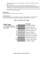
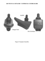
1
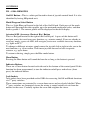
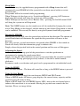
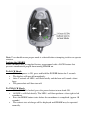
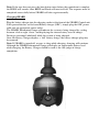
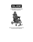
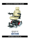
REHABILITATION PRODUCTS
SERIES 8
OWNER/USER MANUAL
IMPORTANT
For your safety and comfort read carefully and understand all of the features prior to
using your new Glide Power Chair.
Misuse may result in electrical or mechanical damage.
Maximum Recommended User Weight 150kg
TABLE OF CONTENTS
SECTION 1.
INTRODUCTION
SECTION 2.
STANDARD FEATURES
SECTION 3.
WARNINGS
SECTION 4.
OPERATING YOUR WHEELCHAIR
SECTION 5.
TRANSPORTING THE POWER CHAIR
SECTION 6.
BATTERY CHARGING AND MAINTENANCE
SECTION 7.
ROUTINE MAINTENANCE
SECTION 8.
TROUBLE SHOOTING
SECTION 9.
PENNY & GILES PILOT + CONTROLLER
SECTION 10.
DYNAMIC CONTROLS CONTROLLER
SECTION 11.
PRECAUTIONS FOR CONTROLLER USE
SECTION 12.
TRANSFERRING TO & FROM YOUR POWER CHAIR
SECTION 13.
BATTERY WIRING DIAGRAM
SECTION 14.
SPARE PARTS
SECTION 15.
WARRANTY
SECTION 1. INTRODUCTION
Thank you for choosing the Glide Power Wheelchair.
An Australian designed and manufactured product, which complies with AS 3695 and
has a manufacturers recommended maximum user weight of 150Kg.
With proper care and operation your wheelchair will provide years of trouble free
mobility.
Please take the time to familiarise yourself with the functions and features of your
power chair by reading this owners manual. If you have any queries about the functions
of the chair you can call Glide Rehabilitation Products or your nearest Glide
Rehabilitation Products dealer.
GLIDE REHABILITATION PRODUCTS
25 LEDGAR RD
BALCATTA
PERTH. WA. 6021
AUSTRALIA
PH: +61 8 9345 3400
Fax: +61 8 9345 1384
SECTION 2. STANDARD FEATURES
The illustration below lists the standard features of the Series 8 Power Chair.
1. Flip up & Height Adjustable Armrests
2. Battery Pack
3. Drive Clutch
4. 10”Front Castor Wheels
5. Controller
6. Sprung Ride Leveling Suspension “POSI TRAK.”
7. Footrests
8. Attendant Brakes
9. Adjustable Seat width & depth
10. Height Adjustable Backrest
11. Adjustable Height Anti – Tip Wheels
12. 4.10/3.50 X 6 Drive Wheels
13. 8” Rear Castors
FIGURE 1. STANDARD FEATURES
SECTION 3. WARNINGS
Read and understand the warnings stated in this section.
To the Occupant
WARNING!
1. Before using this chair, obtain advice and training from your health
professional.
2. Each chair is custom designed to suit individual needs. Take time to become
familiar with each feature before you begin driving.
3. Depending on your level of function and ability, you will need to develop your
own methods for its safe use.
4. Understanding the environment where the chair will be used will help identify
potential hazards and how to avoid them.
5. Read this manual before operating chair.
6. Never take chair onto stairs or escalators.
To the Carer
WARNING!
1. You must read this manual and follow all the instructions in each section as
they also apply to you.
2. You must develop an understanding of the occupants ability to develop safe
methods best suited to your ability
3. To manually push the chair you must make sure that you have control over the
chair before releasing the motor drive clutch.
4. Only use the push handles to move chair. They are specifically designed for
this purpose
5. When helping the occupant overcome an obstacle you must:
• Learn safe methods from your health professional
• Explain clearly to the occupant what you are about to do and what
they are required to do
• Always go straight up or down when traversing curbs or steps. Never
attempt angled approaches or descents as it effects stability of the
chair.
• Never let the chair drop back to the ground when going over edges of
steps and obstacles. Doing so may cause damage to chair or injury to
the occupant
6. Never take chair on to stairs or escalators.
Environment Conditions
WARNING!
The Glide Rehabilitation Products Power Chair has been designed and tested with user
safety, as it’s prime consideration.
The “Posi Trak Suspension System” has been designed to automatically adjust to
uneven surfaces and changes in height, allowing all six wheels to stay in contact with
the ground under most conditions. This feature provides improved stability and traction
in demanding situations.
Even though the “Posi Trak System” improves manoeuvrability and stability, this does
not negate the effect or take into account, circumstances, which put the wheelchair
outside the specified operating conditions for which it was designed and tested.
It is important that the user takes due care and understands the limitations within the
environment that the chair will be operated.
As a guide only, the following is a brief list of scenarios that could affect the stability of
the chair and need to be considered when driving chair: • Traction could be lost on inclined, wet, grassy surfaces. Take extra care and
drive slowly on these surfaces.
• Never drive your chair on a wet, oily or icy covered ramp or slope
• Stop if one or both drive wheels lose traction
• Never traverse railway lines without someone in attendance
• Chair should not be driven in heavy rain
• Never use your chair in a shower, swimming pool, sauna, ocean or lake
• If your environment has many steep obstacles, always have someone in
attendance to assist you.
• Never drive your chair in sand or over rough surfaces. Doing so may cause
damage to wheels, bearings, gearboxes and motors.
• Chairs fitted with Tilt and Recline features should be driven with these features
in the down and upright position. Driving in a Tilted or Reclined position can
affect stability and your vision.
• Maximum safe slope – facing up slope 15 degrees
• Maximum safe slope – facing down slope 15 degrees
Ramps and Inclines
WARNING!
When your chair is on a ramp or incline the centre of balance of your chair will change.
Your chair is less stable when on ramps or inclines and should not be used unless you
feel it is safe to do so. If in doubt have someone with you.
Do not use the chair on a slope of greater than 10 degrees.
When going up an incline or ramp you must:
• Make sure power tilt and recline features are in the down and upright position
• Approach the ramp or incline straight on. Do not approach on an angle (cut the
corner)
• Make sure that you are in the centre of the ramp and that the ramp is wide
enough for your wheelchair
• Not use ramp if you feel that a wheel may drop off the side
• Not veer or turn while on ramp. This may cause chair to tip and a fall may
result.
• Drive chair at a slow, steady speed. Keep chair moving.
When going down a ramp or descent you must:
• You must raise the power seat tilt, to compensate for the ramp angle, so that
the seat is in a near level position.
• Re-adjust seat tilt to a near level position when back on level ground.
• Always use the centre of the ramp or descent
• Not veer or turn while on ramp or descent.
•
•
Drive chair at a slow steady speed .Do not allow chair to accelerate over
normal speed. Centre the joystick to allow it to slow down or stop.
Never use attendant brakes to slow or stop the chair. This may cause the chair
to veer or change direction erratically.
RFI. Warning
WARNING!
All electronic devices generally radiate some type of Radio Frequency Interference
(RFI). The manufacturer of the wheelchair control systems, have made every effort to
minimise the effect of RFI so as not to cause problems under normal circumstances.
Even with the efforts by the manufacturer to minimise effects of RFI, the chair control
system may still be affected in areas with strong RFI signals.
If for any reason, your chair behaves in an abnormal manner, shut the wheelchair off
immediately.
Before continuing, the user must be confident that the system is performing normally. If
not, turn chair off and contact your carer or Glide Rehabilitation Products Agent for
repair.
Controllers
WARNING!
Your chair has been supplied with a fully programmable controller, which has the
ability to fine-tune many driving parameters of your chair.
At time of specification your chair would have been programmed to best suit your
individual function and ability.
Drive the chair in the mode that best suits the environment so as not to cause injury to
yourself or others.
Have an authorised Glide Rehabilitation Products agents make adjustments to the
controller if the chair is not performing to your satisfaction. (There are no controller
adjustments that can be made by the user or carer)
Safety/Performance Check
WARNING!
Make sure the chair operates as it is designed to do.
If there is a change in the performance of the chair or in your functional ability, contact
your nearest Glide Rehabilitation Products agent to reprogram the control settings to
match your needs. It is advisable to have these settings checked annually.
Check for any uncharacteristic noises, vibration or any difficulty in its use.
If a problem is found, notify your carer and Glide Rehabilitation Products agent for
repair or advice on how to repair. Do not drive it if your safety is at risk
Make sure that the batteries are fully charged before operating. The Green float light on
the charger will indicate that the batteries are fully charged.
Make sure all tyres are inflated to recommended pressures and in good condition
Make sure all accessories are secure and in correct position
Check that the electronic brakes work correctly. (When chair is turned on with motors
engaged and hand off the joystick, you should not be able to push the chair or rotate the
drive wheels)
MODIFICATIONS
WARNING!
Never make any modifications or use non-approved Glide Rehabilitation Products parts
on your power chair. Doing so may cause a safety hazard and could void Warranty.
Unauthorised changes constitute remanufacturing of the power chair. This voids any
warranty. The person or group who make the changes will have full liability of the
power chair.
SECTION 4. OPERATING YOUR POWER CHAIR.
CONTROLLER
Your new Power Chair has the option of two types of control systems, Dynamic
Controls or Penny & Giles Controls. You will have been given instruction on how to
operate your controller at time of specification.
WARNING: Never push the On /Off button or pad on the control box until you are
seated correctly in the chair and have your hand on the control box.
IMPORTANT: Please familiarise yourself with the individual functions of your
controller in particular the On\Off button or pad. Both types of control systems have an
On/Off button or pad that operate by pressing once for ON and pressing the same button
or pad again for OFF.
1. Do Not displace the joystick when pressing the on button or pad.
2. Never press the On/Off button or pad while driving your power chair.
3. To avoid damage to motor gearboxes always come to a complete “stop” before
turning your power chair off.
ARMRESTS
The armrests are adjustable in height, position forward or aft of arm pad and flip up
behind backrest.
Height Adjustment
Loosen Turn Wheel located on outside of armrest Post. When adjustment is complete
retighten Turn Wheel firmly.
Forward and Back Adjustment of Arm Pad
Loosen small turn wheel located on the outside and underneath arm pad. Retighten
when adjustment is complete.
Flip Up
To enable armrest to flip up simply depress release lever located on inside of, and at the
base of armrest post. Lift armrest up until release lever locks into position.
FOOTRESTS
The footrests are swing away and detachable. They swing out by pulling the release
lever.
When lever is released the footplate will simply swing out and lift off the two locating
pins.
When refitting footrest to chair ensure that it is located on both locating pins. Damage
may result if only one pin is used.
Height Adjustment of Footplate
Your footplate will be fitted with one of two types of adjustment styles.
1. Clamp Type–to adjust height simply loosen clamp bolt, move to desired
position, retighten clamp bolt.
2. Incremental Hole Type–to adjust height simply un - do and remove bolt, move
footplate to nearest hole to suit desired height, replace and tighten bolt firmly.
DRIVE CLUTCH
The drive clutch is located in the centre of each driving wheel. It is identified as a large
Black Plastic Knob. See Figure 1. Standard Features Point 3.
To ENGAGE, simply turn Black Plastic Knob (drive clutch) in either direction until you
here a “click”. Turn chair on and SLOWLY move joystick forward until drive clutch
self engages.
To DISENGAGE simply pull out and 1/8th turn the Black Plastic Knob (drive clutch).
This will allow the chair to be free wheeled.
BRAKES
Your power chair has electronic brakes and they are activated in the flowing manner.
1. If chair suffers a power failure while driving
2. When joystick of controller is released
3. When chair is turned Off
In addition the power chair is fitted with attendant brakes for use when in free wheel
(drive clutch disengaged).
ADJUSTING THE BACKREST ANGLE
There are 2 options available for backrest angle adjustment
1. Standard on all Series 8 chairs, unless otherwise ordered, is an incrementally
adjustable support strut under the seat. It is advisable to have a Glide
Rehabilitation Products agent make this adjustment.
2. Electrically operated actuator. These are operated in several ways
• Touch pad or button located on controller
• Remote switches located for best access by occupant.
• Changing to actuator on MODE setting and using joystick to adjust.
Please familiarise yourself with this function for trouble free operation.
ADJUSTING THE SEAT ANGLE
There are 2 options available for seat angle adjustment
1. Standard on all Series 8 chairs, unless otherwise ordered, is an incrementally
adjustable support strut under the seat. It is advisable to have a Glide
Rehabilitation Products representative make this adjustment.
2. Electrically operated actuator. This is operated in several ways
• Touch pad or button located on controller
• Remote switches located for best access by occupant
• Changing to actuator on MODE setting and using joystick to adjust.
Please familiarise yourself with this function for trouble free operation
Figure 2. How to Operate your Chair.
SECTION 5. TRANSPORTING YOUR POWER CHAIR
Transporting your Power Chair in motor vehicles can be easily achieved by the
following methods.
STATION WAGON
TRANSPORTING IN A SPECIAL WHEELCHAIR TAXI, BUS OR PRIVATE
VEHICLE WHILE THE USER IS IN CHAIR.
To date there is no recognized Australian Standard that covers wheelchairs suitable for
vehicle transport while the user is in the chair. The Series 8 wheelchair has undergone
Static Pull test for the Vehicle Tie Down Location points to a load specified by the
NATA test laboratory and in accordance with Standards requirements. It is
recommended that a 4-point tie down system is used for anchoring the chair to the
vehicle in conjunction with the occupant restraint system, that must comply with
AS2942-1994. Where possible, wheelchair occupants should be transferred into and use
the proper vehicle seat and restraints.
CAUTION: Do not use leg rests or footplates as attachment points for your tie
down system.
Do not use armrests as attachment points for your tie down system.
Unoccupied wheelchairs in vehicles must be safely secured or stored securely
outside the passenger compartment.
Posture Positioning Belts should not be used as vehicle restraint belts.
NOTE: Ensure that your restraint system complies with AS2942 and you fully
understand the manufacturer instructions on how your tie down system works and
whether it is compatible with the Glide Power Chair
SECTION 6. BATTERY CHARGING AND MAINTENANCE
Keeping the Power Chair working to its maximum potential it is recommended the
batteries be charged every night. This will ensure a longer life for the batteries and chair
will be ready to go when you are.
Your Power Chair battery charger is special to your chair and may not be suitable for
other power chairs.
CHARGING YOUR POWER CHAIR
1. Ensure charger is switched off
2. Ensure wheelchair is switched off
3. Connect charger to wheelchair via the charging socket located on the front of
the joystick module.
• ORANGE “Battery Connected” light will come on
• Connect 3 Pin plug to mains supply and turn on.
• Switch charger on. RED “Power On” light will come on.
• When battery is fully charged GREEN (charge complete) float light will come
on.
NOTE: Chargers may vary slightly so please familiarise yourself with the
manufacturers instructions.
CHARGING TIMES
Charging times may vary depending on usage, battery condition, internal resistance and
age of battery.
In most cases overnight charging (8 – 10 hours) is sufficient.
No harm will be done to batteries by leaving them on charge for a few days. However
prolonged charging is not advisable. EG. 3 days or more.
BATTERIES
Do not store near a heat source or in direct sunlight. Keep the terminals dry, clean and
coat lightly with petroleum jelly to prevent corrosion.
It is advisable to have a Glide Rehabilitation Products representative replace your
batteries.
SECTION 7. ROUTINE MAINTENANCE
DAILY
Charge your batteries every night so your Power Chair is ready to go when you are.
WEEKLY
1. Check tyre pressures (30PSI drive wheels, 30PSI front & rear castors)
2. Clean frame and vinyl parts with mild soapy solution.
3. Wipe upholstery with a clean damp cloth
4. Check function of electric brakes (When chair is turned on with motors
engaged and hand off the joystick, you should not be able to push the chair or
rotate the drive wheels)
5. Check all cables and connectors are secured; i.e. battery, motors and controller.
6. Check both front and rear castors for any excessive movement about the top or
bottom bearing mounts or pintle shaft. Contact your nearest Glide
Rehabilitation Products agent for repair of this fault if it occurs.
MONTHLY
1. Give the chair a general inspection for loose nuts and bolts.
2. Inspect and clean corrosion from battery terminals and cable connectors.
ANNUALLY
It is advisable to have an annual inspection of the Power Chair performed by an
authorised Glide Rehabilitation Products Agent. Their knowledge and experience
enables them to identify and correct problems that might otherwise go undetected.
For any questions concerning procedures or service, contact your nearest Glide
Rehabilitation Products Agent or Glide Rehabilitation Products direct.
USER & MANUFACTURER SERVICEABLE PARTS
The only user serviceable parts are as per Section 14.
All other components are to be repaired by Glide Rehabilitation Products.
PACKING & SHIPPING
The Series 8 Power Chair is shipped to Glide Rehabilitation Products agents in a fully
enclosed pallet mounted cardboard box to minimise damage during transport.
Your chair should arrive to you fully assembled and ready to use.
If your chair needs to be transported interstate or overseas, it is recommended that a
shipping box and pallet be used. These can be purchased from your nearest Glide
Rehabilitation Products agent or dealer.
NOTE: As stated in our warranty, we recommend that your wheelchair be
returned to an authorized Glide Rehabilitation Products agent for it’s free 3 month
service check. This is a one off free service calculated from date of purchase.
SECTION 8. TROUBLE SHOOTING
If your Power Chair will not go, follow this checklist
1. Check that the lights on control box are illuminated.
2. If there are no lights on controller, check that all leads/plugs, which connect to
controller, are pushed in properly.
3. Check that the motor cables are properly connected
4. Check all battery wiring is connected.
5. Check that battery box connector is plugged in.
6. Check circuit breaker located on the battery box lid. The circuit breaker will
trip when the wheelchair is stalled for a prolonged period or if a major fault has
occurred. If circuit breaker continually trips for no apparent reason, cease use
and contact nearest Glide Rehabilitation Products service agent. Important:
Allow 60 seconds before resetting circuit breaker.
7. If you still have problems after reviewing the above checklist, please contact
your nearest Glide Rehabilitation Products Agent or Glide Rehabilitation
Products direct.
SECTION 9. PENNY & GILES PILOT + CONTROLLER
Figure 3. Penny & Giles Controller
CONTROLS
On/Off Pushbutton
This is a green pushbutton switch fitted in front of the joystick, which turns the
controller On and Off. Do not use this switch to stop the wheelchair except in an
emergency.
TruCharge Battery Gauge
This is a 10 segment illuminated display which indicates if the controller is turned On
and also gives the status of the battery, the controller and the wheelchair electrical
system.
Red, Yellow and Green bars illuminated: Battery charged; controller and electrical
system OK.
Red and Yellow bars illuminated: Charge battery if possible, controller and electrical
system OK.
Red bars only illuminated or Slow Flash: Charge battery as soon as possible;
controller and electrical system OK.
Rapid Flash of bars: Indicates a fault in the controller or electrical system. See below
for fault diagnostics.
Ripple Up and Down of bars: Joystick displaced at Turn On. Ensure joystick is in
central position, Turn off and On.
Joystick
Controls the speed and direction of the wheelchair. Push the joystick in the direction
that you wish to go. The further you push it, the faster the speed. Releasing the joystick
stops the wheelchair automatically.
Maximum Speed/Profile Indicator
This is a gauge which shows the maximum speed setting for the wheelchair or, if the
control system is programmed for a drive profile, the selected drive profile.
To change speed/profile you must press the MODE button.
If the mode button is pressed while you are driving the maximum speed setting will be
increased by one step. Each successive operation of the mode button will increase the
setting. There are five settings and the system will toggle to the next setting each time
the mode button is pressed while driving. E.g 1-5 and 5-1
If the MODE button is pressed when the joystick is centred – when chair is stationary
– the control system operation mode will be changed. There are three modes – drive,
speed adjustment and actuator adjustment.
1. To adjust speed when in this mode – The maximum speed can be adjusted by
left or right movements of the joystick. Left will decrease the speed, right will
2.
increase it. Forward or reverse movements of the joystick will take you back
into drive mode.
When the control system is in this mode the actuator indicator will be
illuminated. The section of the wheelchair symbol that is illuminated shows the
actuator that is selected for adjustment. To change the selected actuator move
the joystick left or right. To make adjustments to the selected actuator move the
joystick forwards or backwards.
Horn Button
Horn will sound for as long as button is pressed
Charger Socket
This 3 pin socket is used to connect your battery charger and also to programme/re –
programme controller using the PP1 programmer, should this be necessary.
PENNY & GILES FAULT TREE
Figure 4. Penny & Giles Fault Tree
SECTION 10. DYNAMIC CONTROLS CONTROLLER
Figure 5. Dynamic Controller
CONTROLS
DX – G90A REMOTES
On/Off Button – This is a white pad located in front of joystick control knob. It is also
identified by having 1/0 printed on it.
Mode/Program Select Button
This is a Light Blue pad located to the left of the On/Off pad. Each press of the mode
button will increment the drive profile, up to the maximum configured value, and then
back to profile 1. The current profile will be displayed in the drive display.
Actuator/ASK (Accessory Shortcut Key) Button
This is a Red pad located to the right of the On/Off pad. A press of this button will
navigate you to last used accessory function, e.g. actuator control. If you are already in
accessory mode, a press of ASK, will navigate you to next available accessory function,
e.g. lights or ECU.
To change to different actuators simply move the joystick left or right to take you to the
next function, e.g. tilt or recline. Then move joystick forward or back to operate
actuator, e.g. up or down.
To return to driving, simply press the Blue mode button.
Horn Button
Pressing the Horn button will sound the horn for as long as the button is pressed
Indicator Buttons
These are a Green button located each side and at the bottom of the control panel. If this
function has been programmed, to turn the indicator on/off press and release (short
press) the indicator button.
Jack Sockets
Jack sockets have been provided on the G90A for accessing On/Off and Mode functions
via 3rd party switches.
These connections are protected by a screw down cover and are clearly labelled. When
3rd party switches are connected, ensure the wiring is routed suitably to exit from the
notches in the cover. Carefully replace the cover and retighten the screw.
Figure 6. Dynamic Control Panel
Dynamic Shark Controller
Models
DK – REMA - No Seat Functions
DK – REMB – Two Seat Functions
Controls
All user controls can be accessed from the simple, ergonomically designed panel on the
Shark Control Unit
DK – REMB shown
The Shark Information Gauge
The Shark information gauge is the primary source of user feedback. It displays every
possible status that SHARK may have, including;
• Shark Power On
• True state of battery charge, including notification of when the battery
desperately requires charging.
1. Any green LED’s lit indicate well-charged batteries
2. If only amber and red LED’s are lit, the batteries are moderately
charged. Recharge before undertaking a long trip.
3. If only red LED’s are lit, the batteries are running out of charge.
Recharge as soon as possible.
• SHARK Lock Mode Countdown
• Program, inhibit or charge modes
• Fault indication (Flash Codes)
The following table indicates what the gauge will display for any given state.
Turning the SHARK On and OFF
Turning the Power ON
• Press the Power Button
• All indicators will light briefly
• Either the current battery charge or Lock Mode will then be indicated
Turning the Power OFF
• Press the Power button
• The LED’s will turn off.
Sleep Mode
Some Sharks may be supplied factory programmed with a Sleep feature that will
automatically turn SHARK off if the joystick has not been moved within a certain
period of time.
Sleep mode will not be entered while programming.
When Wakeup style has been set to ‘Joystick and Buttons’, pressing ANY button or
displacing the joystick will bring the system out of Sleep mode.
When Wakeup style has been set to ‘Buttons Only’, pressing the On/Off button ONLY
will bring the system out of Sleep mode.
Note: The SLEEP feature may be turned on or off, the method for bringing the system
out of Sleep Mode can be changed, and the amount of time before Sleep mode is entered
can be modified. This can only be done by using the Dynamic hand held programmer.
Driving the SHARK
Moving the joystick will cause the powerchair to drive in that direction. The amount of
joystick movement will determine the speed that the powerchair will move in that
direction.
For safety reasons, joystick movements are ignored when SHARK is first turned on.
Shark will slowly flash the information gauge to indicate this.
Simply release the joystick back to the neutral position and the error will disappear.
Adjusting the Speed
A user may adjust the top speed of the powerchair to suit their preference or
environment by turning the speed control dial.
Simply turn the dial fully clockwise to travel at top speed when the joystick is pushed
fully forward. The top speed progressively reduces, as the dial is turned counterclockwise.
Parameters such as acceleration and speed can be programmed to suit individual needs.
Using the HORN
Press the Horn Button – The horn will sound for as long as the HORN button is pressed.
Using the Seat Button
Press the seat button to toggle the unit between DRIVE and SEAT mode.
When in DRIVE mode, the battery gauge displays the current battery capacity and the
joystick causes the chair to drive.
When in SEAT mode, the two GREEN battery LED’s next to the seat button light to
indicate the control unit is in seat mode. Moving the joystick now controls the seat
functions. Please see image below.
Note: User should ensure proper mode is selected before attempting to drive or operate
actuator.
Locking the SHARK
Some SHARKS may be supplied factory programmed with a LOCK feature that
prevents unauthorised people from turning SHARK on.
To LOCK Shark
• While the power is ON, press and hold the POWER button for 2 seconds
• The display will turn off immediately
• After 2 seconds all LED’s will flash briefly and the horn will sound a short
beep.
• The powerchair will then turn off.
To UNLOCK Shark
• While SHARK is locked, press the power button to turn shark ON.
• All LED’s will flash briefly. The LED’s will then perform a slow right to left
countdown.
• Press the HORN button twice before the countdown is completed (approx 10
seconds)
• The current state of charge will be displayed and SHARK may be operated
normally.
Note: If the user does not press the horn button twice before the countdown is complete,
the HORN will sound a short BEEP and Shark will turn itself off. The sequence must be
completed successfully before SHARK will drive again normally.
Charging SHARK
Plug the battery charger into the charging socket at the front of the SHARK Control unit
If the powerchair has an On-board Battery charger (OBC), simply plug the OBC power
cable into an appropriate power outlet.
The SHARK Information Gauge will indicate the system is being charged by cycling
between a left-to-right ‘chase’ and displaying the current battery state-of-charge.
Driving is prevented (inhibited) while the system is being charged.
Once the battery Charger displays a ‘full’ battery charge, the battery charger plug may
be removed.
Note: If SHARK is turned off, or goes to sleep while charging, charging will continue.
Although the SHARK Information Gauge will display an approximate battery level
while charging, the Battery Charger should be used as the sole judge of charge
completion.
SECTION 11. PRECAUTIONS FOR CONTROLLER USE
The Dynamic and Penny & Giles controller has been designed with the user safety as
the prime consideration. They incorporate many, sophisticated self – test features which
search for potential problems. If the controller detects a problem either in its own
circuits, or in the wheelchairs electrical system, it may decide to halt the wheelchair
depending on the severity of the fault. The controllers are designed to maximise the user
safety under all normal conditions.
In spite of their sophistication, the controllers cannot take into account, circumstances,
which put the wheelchair or controller outside their specified operating conditions, and
so it is important that the user follows the following precautions.
1. Do not drive the wheelchair:
• Beyond restrictions indicated in the user manual.
• In places or on surfaces where a loss of wheel grip could be
hazardous, for example on wet grassy surfaces.
• If the controller or other crucial components are known to require
repair.
In the event of the wheelchair moving in an unexpected manner release the joystick.
This action will stop the wheelchair under any circumstances.
2. Although the controllers are designed and manufactured to be extremely
reliable and each unit rigorously tested, possibility of a system malfunction
always exists (however small the probability). Under some conditions of
detected system malfunction, the controller must (for safety reasons) stop the
chair instantaneously. If the physical impairments of the user are such that a
sudden braking action could result in a fall from the chair, it is advised that a
restraining device be fitted.
3. It is recommended that a restraining device be used when operating the Power
Chair.
WARNING: Penny & Giles and Dynamic Controls accept no liability for losses of
any kind arising from unexpected stopping of the wheelchair or improper
programming of the controller or improper use of the wheelchair or controller.
SECTION 12. TRANSFERRING TO AND FROM YOUR POWER
CHAIR.
The Glide Rehabilitation Products Power Chair is designed in such a way that
transferring in and out can be done with a minimum of fuss.
1. Make sure that your chair is turned off before transferring.
2. Armrests can flip back allowing easy lateral movement from either side of
chair or for the fitting of a patient hoist sling.
3. If occupant is ambulant, or able to do standing transfers, removing swing away
footplates will allow better placement of feet when standing or conversely,
closer access to seat when transferring into chair. Where possible have
someone assist you during the transfer.
4. You will need to learn safe transfer techniques from your health professional.
5. Always have chair as close as possible to chair that you are transferring to.
6. Ensure that the front castors are facing forward when transferring.
7. If your chair is fitted with Power Operated Seat Tilt or Recline functions,
ensure that they are in the down and upright position before attempting to
transfer.
8. Ensure that your wheelchair brakes are applied
SECTION 13. BATTERY WIRING DIAGRAM
2 x 36Amp Hour Sealed Deep Cycle Batteries
Consult your Glide Rehabilitation Products agent when replacement is required.
Figure 7. Battery Wiring Diagram
SECTION 14. SPARE PARTS
User Serviceable Parts
TYRES
8” Pneumatic Front & Rear (200 x 50)
Part Number – 202602
9” Pneumatic Front (2.80/2.50)
Part Number – 202604
10” Pneumatic Front (260 x 85)
Part Number – 202670
12 ½ x 2 ¼ Mid Wheel (Narrow)
Part Number – 202615
4.10/3.50 – 6 Mid Wheel (Wide)
Part Number – 202663
TUBES
8” Front & Rear
9” Front
10” Front
4.10/3.50 – 6 Mid Wheel
12 ½ x 2 ¼ Mid Wheel T.P.
Part Number – 202492
Part Number – 202504
Part Number – 202566
Part Number – 202567
Part Number – 202501
CASTOR PINTLE AXLE ASSEMBLY
1. Dust Cap
2. Top & Bottom Bearings
3. Pintle Axle
4. Top 12mm Nyloc Nut
5. Castor Fork 8”
6. Castor Fork 9”
7. Castor Fork 10”
8. Castor Wheel 8”
9. Castor Wheel 9”
10. Castor Wheel 10”
11. Castor Wheel Bearings 8”, 9”,10” Wheels
12. Bearing Spacer 8” Wheel
13. Bearing Spacer 9” & 10” Wheel
14. Spacer Washers
15. Castor Wheel Mounting Bolt 8”
16. Castor Wheel Mounting Bolt 9” & 10”
17. Nyloc Retaining Nut
Part Number – 62021
Part Number – 20018
Part Number – 620046
Part Number – 783846
Part Number – 20073
Part Number – 20079
Part Number – 20078
Part Number – 20121
Part Number – 20128
Part Number – 20127
Part Number – 20014
Part Number – 60622
Part Number – 606301
Part Number – 7827
Part Number – 78745
Part Number – 7878
Part Number – 783841
SECTION 15. WARRANTY
Lendal Pty Ltd (trading as Glide Rehabilitation Products) warrants the following as
listed:
Controllers
12-months warranty
Controllers and associated hardware will be repaired where possible. Replacement will
only occur if repair is not practical or not possible.
Motors/Gearbox
12-months
Automatic replacement within six months of invoice. There afterwards, unit must be
returned for evaluation and possible repair before replacement.
Actuators
12 months warranty.
Automatic replacement within six months of invoice. There afterwards, unit must be
returned for evaluation and possible repair before replacement.
Frame
3-year warranty
Frame will be replaced within the first twelve month period. Thereafter, Glide will
extend the warrant for further two years and will either replace or repair frame.
Upholstery
6 month warranty
This will cover against defects in materials or workmanship. Warranty does not cover
against normal wear or damage.
Tyres and Tubes
No Warranty
Spare Parts
All spare parts sold will have a 6 months warranty period from date of purchase.
This warranty does not extend to parts or electrical components damaged by misuse,
neglect, accident or improper installation, nor those tampered with, altered or serviced
by an agency not authorised by Lendal Pty Ltd.
The foregoing in lieu of all other warranties expressed, implied or statutory, Lendal Pty
Ltd’s sole liability shall be to repair or replace parts of components as specified above.
1.
2.
IMPORTANT
Lendal Pty Ltd (trading as Glide Rehabilitation Products) does not warrant
either expressly or impliedly the suitability of the Glide Series 8 electric
wheelchair for the purchaser or any intended user. Purchasers and intended
users are advised that advice from an appropriate registered medical
practitioner should be obtained prior to using an electric wheelchair.
Except insofar as is prohibited by statute, Lendal Pty Ltd shall not be
responsible for damage, injury or loss of any kind to any property or
person howsoever caused arising from or in connection with the Glide
Series 8. All conditions and warranties that (but for this provision) would
be implied in favour of, and all rights and remedies that (but for this
provision) would be conferred upon the purchaser or other persons against
Lendal Pty Ltd arising under or as a result of the Trade Practices Act 1974,
any other legislation or the general law are excluded and limited to the
maximum extent possible and in cases where Lendal Pty Ltd’s liability
cannot be completely excluded but may be limited, the liability of Lendal
Pty Ltd is limited to one of the following (at the option of Lendal Pty Ltd)
a)
The replacement of the Glide Series 8 or the supply of an
equivalent wheelchair
b)
The repair of the Glide Series 8
c)
The payment of the cost of replacing the Glide Series 8 or of
acquiring an equivalent wheelchair
d)
The payment of the cost of having the Glide Series 8 repaired
REHABILITATION PRODUCTS
Glide Rehabilitation Products are manufactured in Australia by Lendal
Pty. Ltd. (ACN 009 003 694)
25 Ledgar Rd Balcatta, Western Australia 6021
Australia
Phone: +61 8 93453400 Fax: +61 8 93451384
Email: [email protected]
Web: www.glide.com.au