1
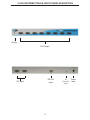
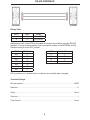
2x8 DVI DA
USER
MANUAL
www.gefen.com
ASKING FOR ASSISTANCE
Technical Support:
Telephone
(818) 772-9100
(800) 545-6900
Fax
(818) 772-9120
Technical Support Hours:
8:00 AM to 5:00 PM Monday through Friday PST.
Write To:
Gefen Inc.
C/O Customer Service
20600 Nordhoff St.
Chatsworth, CA 91311
www.gefen.com
[email protected]
Notice
Gefen Inc. reserves the right to make changes in the hardware, packaging and any
accompanying documentation without prior written notice.
The 2:8 DVI Distribution Amplifier is a trademark of Gefen Inc.
© 2007 Gefen Inc., All Rights Reserved
TABLE OF CONTENTS
1
Introduction
2
Operation Notes
3
Panel Descriptions
4
Dip Switch Settings
5
IR Code Conflicts
6
RS-232 Interface
7
Specifications
8
Warranty
INTRODUCTION
Congratulations on your purchase of the 2:8 DVI Distribution Amplifier. The 2:8 DVI distribution amplifier is an innovative solution for anyone with more complex computer system
requirements, like studios and presentation venues where multi-viewing is essential. The
2:8 DVI distribution amplifier accommodates various system scenarios. Most commonly,
two video sources (either DVI-equipped computer, DVD player or satellite set top box)
are connected to the distribution amplifier on one side. On the output side, eight video
outputs are available to be used in part or in full. Once the unit is connected and powered,
each source can be routed to multiple displays. All DVI displays are driven by the two DVI
sources with each source or computer capable of driving eight displays at one time. For
home theater applications, the unit is HDCP (high definition content protection) compliant,
making it effective for use with all DVI displays.
How it works:
Gefen’s Gefen 2:8 DVI distribution amplifier is an expandable distribution hub that sends
the same DVI graphics source to eight DVI based digital screens (flat panels or projectors). It is a flexible solution that accommodates multiple DVI displays. You can switch from
source one and two via the RMT-2IR remote control. The 2:8 DVI distribution amplifier is
also equipped with an auto sensing feature to switch between whatever source is active.
When one source is inactive it will automatically switch to the active source.
The Gefen 2:8 DVI distribution amplifier is connected with a DVI (male to male) cable from
the DVI graphic source to the distribution amplifier input. There are eight DVI outputs in
each module. DVI output one is the primary connection and is used for the main display.
DVI output 2 thru 8 follow the main display. The 2:8 DVI distribution amplifiers is using a
unique DVI Bus™ technology to connect multiple amplifiers without sacrificing a DVI output
connection. The ninth output is an expansion output used to daisy chain an additional 2:8
DVI Distribution Amplifier. The 2:8 DVI Distribution Amplifier is expandable to 256 outputs
(32 DVI DA’s).
Contents:
The 2:8 DVI Distribution Amplifier consists of:
(1) 2x8 DVI Distribution Amplifier
(1) DVI 6ft Male to Male Cables
(1) 24VDC Power Supply
(1) RMT-2 IR Remote
(1) User Manual
1
OPERATION NOTES
READ THESE NOTES BEFORE INSTALLING
OR OPERATING THE 2:8 DVI DISTRIBUTION AMPLIFIER SYSTEM
• All the monitors connected to the 2:8 DVI Distribution Amplifier must be able to run at the
same native resolution. The 2:8 DVI Distribution Amplifier does not scale the video.
• The 2:8 DVI Distribution Amplifier units are housed in a metal box for better RF shielding.
• You must connect the sources and displays prior to applying power to the unit.
2
2:8 DVI DISTRIBUTION DA FRONT PANEL DESCRIPTION
IR Eye
DVI Output
RS-232
Input
DVI Input
3
IR
Extender
Input
Power
Input
DIP SWITCH SELECT SETTINGS
DIP SWITCH
EDID GUIDE
Extended display identification data (EDID) is a data structure provided by a display to
describe its capabilities to any source that asks for it. The EDID includes manufacturer
name, product type, timings supported by the display, display size, luminance data, (for
digital displays only) pixel mapping data, supported audio channels and formats. This
information is used by the source to cater its output to resolutions and audio formats
that are supported by the display.
Additional EDID modes are available and configured using a combination of dip
switches 1, 2, and 5. Please refer below for the different EDID modes.
To access the Dip Switches, remove all screws from the bottom and sides of the Gefen
unit. Remove the hex screw heads from each side of the rear DVI & RS-232 ports.
Carefully slide the unit apart. The 8 Bank of Dip Switches are located on the main PCB.
Once adjustments are complete, slide the unit back together and replace all removed
screws.
EDID Mode 0 (Switch 1=OFF Switch2=OFF Switch5=ON)
-EDID is copied from the first HDMI port
EDID Mode 1 (Switch 1=ON Switch2=OFF Switch5=ON)
-Same as Mode 0 and adds basic audio support
EDID Mode 2 (Switch 1=OFF Switch2=ON Switch5=ON)
-Same as Mode 0 and adds full audio support
EDID Mode 3 (Switch 1=ON Switch2=ON Switch5=OFF)
-EDID is generated based on the common video and audio features of all of the
connected devices
EDID Mode 4 (Switch 1=OFF Switch2=ON Switch5=OFF)
-Same as Mode 3 and adds basic audio support
EDID Mode 5 (Switch 1=ON Switch2=OFF Switch5=OFF)
-Same as Mode 3 and adds full audio support
EDID Mode 6 (Switch 1=OFF Switch2=OFF Switch5=OFF) DEFAULT
-EDID is generated based on the common video features of all of the connected
devices and the combined audio features of all of the connected devices
4
IR CODE CONFLICTS
How to Resolve IR Code Conflicts
There are matching pairs of dip switches underneath the 2x8 DVI DA unit and under the
remote battery cover. Switch 1 & 2 on the Remote and Switch 3 & 4 inside the unit are the
matching switches. These switches need to be matched for the remote to
communicate with the switcher. There are 4 possible sets of IR codes and at least one of
these sets should be able to resolve any IR conflicts with other home theater devices.
Remote Channel 1:
Remote
1
2
1
2
1
2
1
2
Remote Channel 2:
Remote Channel 3:
Remote Channel 4:
2:8 DVI Distribution Amplifier
Remote Channel 1:
Default
Remote Channel 2:
1 2 3 4 5 6 7 8
1 2 3 4 5 6 7 8
Remote Channel 3:
Remote Channel 4:
1 2 3 4 5 6 7 8
1 2 3 4 5 6 7 8
5
RS-232 INTERFACE
Binary Table
ASCII
1
2
Input
1
2
Binary
0011 0001
0011 0010
Additional control of the EDID modes and IR channel are possible using the RS-232
interface. For any of these modes to be successfully written to the EEPROM, all Dip
Switches must be in the OFF position.
ASCII
m0
m1
m2
m3
m4
m5
m6
EDID Mode
0
1
2
3
4
5
6
ASCII
r1
r2
r3
r4
Remote Channel
1
2
3
4
OK is printed out on screen when a mode has successfully been changed.
Terminal Settings
Bits per second ...................................................................................................... 19200
Data bits ........................................................................................................................ 8
Parity ....................................................................................................................... None
Stop bits ..........................................................................................................................1
Flow Control ............................................................................................................ None
6
SPECIFICATIONS
Video Amplifier Bandwidth ................................................................................. 1.65 GHz
Single Link Range ......................................................................................... 1920 x 1200
Vertical Frequency Range ....................................................................................... 60 Hz
DVI Input/Output Connector Type ....................................................... DVI-I (Digital Only)
Power Consumption ................................................................................ 60 Watts (max.)
Power Supply ........................................................................................................ 24VDC
Dimensions ................................................................................... 17”W x 1.75”H x 7.5”D
Rackmountable .......................................................................................... 1 Rack Space
Shipping Weight ....................................................................................................... 8 Lbs
7