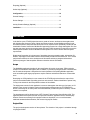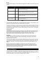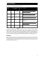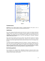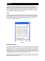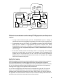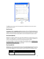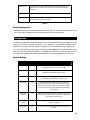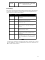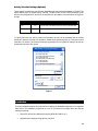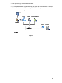
1
PACIFIC STATES MARINE FISHERIES COMMISSION 205 SE Spokane Street, SUITE 100, Portland, OREGON 97202 PHONE (503) 595-3100 FAX (503) 595-3232 Minutes PIT Tag Steering Committee May 27, 2004 Web Teleconference Attendees: Ann Setter (ODFW), Doug Marsh (NOAA Fisheries), Ed Buettner (IDFG), Charles Morrill (WDFW), Tom Hoffman (USFWS), Carter Stein (PSMFC), Don Warf (PSMFC), Dave Marvin (PSMFC), John Tenney (PSMFC), Sean Casey (Digital Angel), Jon Mueller (Digital Angel), Bill Kemp (Digital Angel), Sandy Downing (NOAA Fisheries), Earl Prentice (NOAA Fisheries), Dean Park (Biomark), Steve Anglea (Biomark), Dennis Schwartz (USACE), Kim Fodrea (BPA) 1. The Committee discussed whether it was still interested in pursuing pre-loaded needles. It was recalled that the motivation for this project was a NWPCC fish marking project scheduled at Lower Granite Dam in spring 2004, sponsored by NOAA Fisheries. When this project was delayed, and pre-loaded tags were no longer required, the tag manufacturer stopped work on the pre-loaded needle project. Doug Marsh said that anywhere from 190,000 to 303,000 pre-loaded tags would be required for this project in spring 2005. Carter will prepare a draft memorandum from PTSC members to FPAC that recommends an early funding commitment by BPA, CBFWA and NWPCC for FY2005 PIT Tag Marking Projects based upon a “Master PIT Tag Forecast” list. 2. Sean Casey Presented a Status Report for the Bonneville High-Q PIT System. A. Phase 1 of this project (feasibility and funding) resulted in a “Go” decision. B. Phase 2 of this project is construction and testing of a prototype antenna. The manufacturer of the antenna prototype has slipped the schedule a week or more. The “Go/NoGo” decision to move forward to Phase 3 (Installation) is still scheduled for August 15, 2004. Tag evaluation at the prototype test site is scheduled for October 2004. 3. Sean reported that Digital Angel is moving forward with an ‘interim glass’ tag (TX1400SGL) that which will perform better that the current ‘super-tag’ (TX1400ST). Some limited samples of prospective final tags (the tag after the interim tag) will be available in October 2004. 6,000 tags will be delivered to BPA to use with the radio tag marking study to be conducted in spring 2005. An improved version of this ‘interim tag’ may be available for selection through an evaluation process in 2006. Sean voiced concern about potential PIT tag degradation when used in combination with Radio Tags (i.e., there is concern regarding radio interference from the battery powered tag reducing the delectability of the PIT tag.) “To promote the conservation, development and management of Pacific coast fishery resources through coordinated regional research, monitoring and utilization” Minutes May 27, 2004 PTSC Meeting The following information was offered by Sean subsequent to the conference call: I got two samples of radio tags from Tim Counihan (USGS) per a request from Kim Fodrea. One radio tag was designed for yearlings (KM Tag) and the other for sub-yearlings (Nano Tag). The KM Tag had a magnet that was removed to initiate the battery and the Nano tag did not. There was no impact on the reader system when the KM tag was operating. The PIT Tag used was one of the first samples of the interim glass tag. The test was conducted on the 16 x 16 foot antenna at DA. The tags were located 4 feet vertically above the wire at the outer face of the antenna. The tags were at 0 degrees orientation (optimal). The number of reads were logged out of a possible of 1000 using a universal counter. Due to periodic noise at the site caused by the near-by freeway, the efficiencies varied throughout the test. In order to mitigate this for comparison purposes, the efficiency of the PIT Tag alone was tested first, and then immediately the radio tag was applied. Following the testing of the radio tag/ PIT Tag combination the PIT Tag alone was tested again to verify the environment. If noise was detected, we tested the configuration again. Higher noise was seen during the last test (both configurations). Three tests were run on Radio Tag/ PIT Tag combination: Test 1). Pit Tag parallel to the Radio Tag, with the PIT Tag antenna located opposite the radio tag antenna. Test 2.) Pit Tag parallel to the Radio Tag, with the PIT Tag antenna located towards the radio tag antenna. Test 3.) PIT Tag perpendicular and in the middle of the Radio Tag. Test Results: Nano Tag Test 1: PIT Tag alone = 778, PIT Tag/ Radio Tag = 1 Test 2: PIT Tag alone = 831, PIT Tag/ Radio Tag = 183 Test 3: PIT Tag alone = 138, PIT Tag/ Radio Tag = 46 KM Tag Test 1: PIT Tag alone = 724, PIT Tag/ Radio Tag = 232 Test 2: PIT Tag alone = 682, PIT Tag/ Radio Tag = 360 Test 3: PIT Tag alone = 385, PIT Tag/ Radio Tag = 217 Observations: PIT Tag signal was noticeably reduced when placed near the Radio Tag, sometimes up to 50%. The KM tag had less impact on the PIT Tag performance than the Nano Tag, possibly due the battery orientation as the Nano tag battery is on end and provides a larger metal surface area to the PIT Tag. Conclusion: The radio tag has a significant impact on the performance of the PIT Tag in the 16 x 16 foot antenna that will be used for the Hi-Q system. 4. Kim Fodrea is responsible for evaluation of the High Q system’s fish Detection Efficiency and requested suggestions from the PTSC on how to perform the evaluation. Dennis Schwartz is investigating the possibility of getting between 200 and 1000 fish to be tagged with equal numbers of ‘interim tags’ and ‘2006 selected’ tags that could be marked and released with the Spring Creek fish in March 2005. Charles Morrill said he would make inquiries for fish in order to facilitate the Spring Creek release test. Subsequently, Charles reported that WDFW has located 25K Spring Chinook for the study at Carson NFH (special thanks to Dave Wills). Page 2 PTSC_May_27_2004 Minutes May 27, 2004 PTSC Meeting BPA and the Corps are investigating the feasibility of ‘piggy-backing’ on other tagging projects (combined radio tag / PIT tag, similar to what is used in the McNary Survival and Migration study), as a means to determine detection efficiency of the High Q PIT system. Dennis Schwartz and Kim Fodrea will set up a meeting for ‘positioning on a “One-Pager”’ to develop a proposal for the Corps’ program, although funding of the Detection Efficiency study will be through the NWPCC’s Fish and Wildlife Program and funded through BPA. Sean suggested that the interim tag (TX1400SGL) and the ‘new tag’ (previously referred to as ‘2006 selected’) should be tested in order to correlate all previous dry testing in order to give possible information on fish location and system efficiency in 2005. 5. Jon Mueller gave a status update on the Generation 2 (G2) Transceiver Development John Tenney indicated that data can be lost using the network interface to the G2 reader as it is currently implemented. This is because UDP protocol being implemented has no error correction (UDP is generally used for streaming voice or video – data types that, in general, can tolerate the loss of data packets here or there). John suggested switching to the TCP protocol or developing an error correction protocol for UDP. The PTSC had no objections to testing the G2 prototype at data collection sites at main stem dams or at in-stream detection locations sometime during summer 2004. This would involve taking a single coil off-line (e.g., coil 01, the first antenna of the full flow bypass at McNary Dam), and connecting that antenna cable to the G2 reader. This testing is intended to identify any gross problems with the G2 reader interface. Since the G2 reader has a different data format from the FS1001, FS2001 or FS1001A, data taken during this testing would not be submitted to PTAGIS. 6. John Tenney gave an update of the MobilMon data logger. John asked for input to the Functional Specification (1st Draft, May 20, 2004). He explained that this was a Windows CE based system that was developed to support Digital Angel’s new “G2” transceiver and would be backward compatible with the FS1001, FS1001A and FS2001F-ISO and multiplexor PIT tag readers. Earl Prentice suggested that this effort competes with the private sector. Carter explained that it does not since there is no such Windows CE solution available, and there is no solution available for data collection of the new ‘G2’ reader system. 7. Sandy asked for comments on the Draft Lab Test for New Tags protocol that she sent to the Committee. The document was focused on the smaller coils used at the juvenile fish facilities, since the PTSC spent so much time discussing this at their January 2004 meeting. However the Committee agreed that the scope of the tests should also address larger antennas to the extent practical. Both Sean Casey and Earl Prentice offered large pipes for use by PSMFC in testing tags in their RF shield room in Kennewick, WA. However, it may be most practical to wind antennas on 2”x4” wood frames inside the room in order to maximize flexibility of the antenna sizes that can be tested and to save warehouse space and eliminate transportation costs. Page 3 Send comments on this draft to Sandy by June 11, 2004. PTSC_May_27_2004 Minutes May 27, 2004 PTSC Meeting 8. An ad-hoc discussion occurred regarding the biological study of tag encapsulation materials in fish (See Tag Packaging / Tag Coating – PTSC Minutes Aug. 21, 1993) being conducted by U.S. Fish and Wildlife Service (Joe Zydlewski). Tom Hoffman will inquire about the project and report back to PTSC. 9. Don Warf reported that the Corps (contact Chuck Cross in Portland District) design for vertical slot antennas at Bonneville Washington Shore is 90% complete. The BCOE is scheduled to be distributed on July 7 and the construction window is between Dec. 1, 2004 and Feb. 28, 2005. Antennas are currently being fabricated by Digital Angel and will be shipped to Bonneville when complete, and stored there until they are installed in the winter. PTSC members should consider whether or not they wish to support using the new ‘G2’ transceiver for data collection on the new slot weirs at Bonneville in 2005. 10. Don Warf reported that the Corps 60% design submittal for installation of a full flow bypass at Ice Harbor will be completed soon and that the 100% submittal should be completed by July. Construction is scheduled between Dec. 15, 2004 and March 15, 2005. Full flow bypass installation at Lower Monumental is delayed until 2006. PTSC members should consider whether or not they wish to support using the new ‘G2’ transceiver for data collection on the new full flow bypass at Ice Harbor in 2005. 11. The PTAGIS project budgeted the installation of two “Separator Adult Return” monitors. One monitor was installed earlier this year at McNary. Although PTAGIS is prepared to move forward with the installation of the second unit at Little Goose, the committee asked for additional information before an installation decision was made. Dave Marvin will contact Bob Wertheimer (and other Kelt researchers) to determine which adult return flumes at the main-stem project would provide the best benefit for studies. Dave will report back to the PTSC. 12. Ann Setter reported that the FPAC approved of the PTSC’s PIT Tag Approval Process and the PTSC’s Ethics document. Carter spoke with Dave Wills and heard that theTag Approval Process was agreed to by the FPAC but they had not taken up the topic of the Ethics issue. Carter asked Dave Wills for minutes of the FPAC meetings, but Dave wasn’t sure he knew where to get them. 13. Dave Marvin asked the Committee to consider a new naming convention for Interrogation Site Codes to deal with potentially non-permanent interrogation sites that were being set up at USFWS sites in Carson and Little White Salmon. The Committee will discuss after a written proposal is prepared. Ann Setter will write a definition for adoption by the Committee. 14. Dave Marvin suggested the Committee take a position advocating a “New Route at McNary” (see MicroSoft Power Point: New Route at MCJ.ppt at www.ptagis.org). Page 4 The Committee deferred this item until its July meeting. PTSC_May_27_2004 MobileMon Functional Specification First Draft John Tenney Last Updated: 5/20/2004 Table of Contents Table of Contents..............................................................................................1 Introduction........................................................................................................2 Scope ...................................................................................................................2 Project Plan..........................................................................................................2 Supported Platforms ........................................................................................3 Supported Devices ...........................................................................................4 Commands ..........................................................................................................4 Terminal Services................................................................................................5 Identification.........................................................................................................5 Auto Sensing (optional).......................................................................................5 Data......................................................................................................................6 Record Types ......................................................................................................6 Time Zone Standardization (Optional) ...............................................................6 Operation............................................................................................................7 Status ...................................................................................................................7 MobileMonSync Manager...................................................................................7 Application Logging .............................................................................................8 Data Download....................................................................................................9 Data Upload (Optional) .......................................................................................9 1 Reporting (Optional) ............................................................................................9 Online Help (Optional).......................................................................................10 Configuration...................................................................................................10 General Settings................................................................................................10 Device Settings..................................................................................................11 Activity Schedule Settings (Optional) ...............................................................13 Installation........................................................................................................13 Introduction In the last few years, PTAGIS project has seen a growth of remote, small-stream interrogation sites with limited power resources. Some of these sites power a laptop running MiniMon software for realtime data acquisition. Other sites that cannot power a PC require a user to periodically visit the site and download the readers’ buffers into MiniMon and append the records into a single interrogation file. Over the past year, there have been several requests from the PTAGIS community for this project to provide data acquisition software similar to MiniMon that will operate on a PDA PC device with lower power requirements. Digital-Angel Corporation is in the process of developing the next generation reader, dubbed the ‘G2 Reader’. A prototype of this reader has been delivered that provides a limited feature set. The PTAGIS project has a technical role in the development of this reader and has an assigned deliverable to provide a prototype of data acquisition software to interface with the G2 Reader. Scope The MobileMon application described in this specification will provide a low-power, PDA monitoring solution for small-stream interrogation sites. In addition, it provides a prototype solution to interface with the G2 reader development. It will perform the basic operations of the existing MiniMon application, such as interfacing with legacy equipment to acquire real-time and buffered data into a common data store. Developing on a PDA platform is a new venture for the PTAGIS project; therefore the scope of this project is somewhat flexible. Depending upon time and resources, features identified as ‘optional’ may or may not be included in the final production release of the software. The deployment scenario for this application is a remote interrogation site with up to four legacy or G2 readers. Power source is limited to running the interrogation equipment and an OTS PDA device. Device connectivity can be serial (cable or wireless Bluetooth) or Ethernet (cable or wireless). A WAN network is not required. The development tools for this project are .NET Compact Framework and Visual Studios 2003. This application will be developed in C# and use open source libraries, application blocks, and third party libraries. Resources necessary for this project include one developer, one or more beta testers, additional hardware/software libraries, and access to legacy/G2 readers. Project Plan The project development consists of three phases. The duration of this project is scheduled through July/August of 2004. 2 Design The first step of this phase is to model critical technology that is necessary to develop this project; this includes: Critical Technology Status Notes PDA serial I/O connectivity Complete Using open source libraries for the .NET Compact Framework, a project will be developed to read/send serial I/O. PDA Ethernet connectivity Complete Using a third-party library for the .NET Compact Framework, a project will be developed to read/send UDP data packets from the G2 reader. PDA FTP connectivity Pending Using a third-party library for .NET Compact Framework, a project will be developed to make a stable FTP connection with the PTAGIS network for optional PTTP transactions. PDA I/O throughput and performance evaluation Pending An instrumented prototype will output the performance characteristics for serial and Ethernet (UDP) I/O. Table 1 The second step of this phase will be a completed functional specification. This specification will be delivered to PTAGIS personnel and other interested parties for comments. The last step of this phase is to produce a design document that will include the architecture and object model proposed for developing this project. The object model provides the PTAGIS development team a ‘prototype object model’ for some of the basic features that may be reused in future G2 Interrogation software development. Implementation This phase begins the actual construction and integration of the software. Basic unit testing will also be a part of this phase with a target PDA platform and peripheral devices. Phase I of the implementation will only include critical functionality identified in this function specification. Phase II of the implementation will include optional functionality based upon resource, time and necessity. Evaluation In this final phase, the solution is integrated onto the target platform(s) and system testing (which includes a subsequent I/O throughput and performance analysis) is performed in-house with the supported peripheral equipment. The next step of this phase is to perform field testing. Biomark has already expressed their cooperation in performing the necessary field testing for this project. Once field testing is complete, the solution will be installed in beta sites. These sites have been identified by Biomark and target installation is July 2004. Once the evaluation phase is completed, the PTAGIS web site will include software section for MobileMon which will include online/PDA documentation, information on supported devices, and a download section for the production software. An announcement will also be made to the PTAGIS community for the production release of this software. Supported Platforms The target platform for MobileMon is Microsoft® Windows® Mobile 2003 Premium for Pocket PC (Windows CE). If time and resource is available, the MobileMon application may be ported to run on a common Win32 platform, such as WinXP and Windows 2000 if requested. 3 Supported Devices MobileMon will support the following types of devices: Device Type Protocol Communication Interface Firmware Specifications G2 Reader XML Serial, Ethernet, USB (optional) N/A Software Design Document: Digital Angel Reader and Remote Configuration Software; Revision B, Logic Product Development. FS-1001 BPA, ASCII Serial 2.11 Multiple Transceiver System FS1001 User Manual; Release 1.0; Destron-Fearing. FS-1001A BPA, ASCII Serial 3.11 Multiple Transceiver System FS1001A User Manual; Preliminary Release 1.0 (Version 3.8); Destron-Fearing. SSR-MUX ASCII Serial 1630.1.0 Various email correspondence with Digital Angel and Steve Lemay FS-2001 ASCII Serial 2.1, 1.5, 3.8 (ISO) Portable Transceiver System PTS Model FS2001F-ISO Preliminary User Manual; Release 1.0; Digital Angel. GPS (optional) ASCII Serial N/A N/A Table 2 MobileMon will allow the user to configure and connect to one or more types of devices. The total number of devices is TBD based upon performance testing with serial interface hubs. MobileMon will acquire, decode, categorize, timestamp, and store all messages from these devices. Messages may be sent from any device in real-time or from a download/buffer mechanism. If messages are downloaded from a device, the internal timestamp of the stored messages will overwrite the system timestamp. Commands A list of common commands for each type of configured device will be presented to the user (Figure 1). While the application is in ‘Monitor’ state (see Operation section), the user can select a device and send commands to that device. If all configured devices are of the same type, the use can broadcast a single command to all connected devices. 4 0RELOH0RQ 0RQLWRULQJVLQFH30 6HOHFWD'HYLFH $$)6$ %URDGFDVW&RPPDQG 6HOHFWD&RPPDQG 'RZQORDG'DWD 6HW$ODUP7KUHVKROG 6HW'HYLFH'DWH7LPH 'LVSOD\6WDWXV (UDVH$OO)LOHV &ORVH&XUUHQW)LOH ') ;; '' '6 )($ )(& 6HQG 'DWD $ODUPV &RQILJXUH &RPPDQGV 5HSRUWV 0RQLWRU 6WDQG%\ Figure 1 Terminal Services MobileMon will not support terminal services. A separate third-party OTS product, such as HyperTerminal, may be made available for troubleshooting serial devices. Identification Part of the messaging functionality requires each device have a unique, two character hexadecimal identifier, referred to as a Device ID. This identifier is usually configured on the physical device and embedded in the messages sent to the client application. However, some device protocols do not embed Reader ID in the message and it is up to the client application to associate a predefined identifier with a particular device. Some reader devices support more than one antenna. This requires each antenna to be uniquely defined with a similar two character hexadecimal code, referred to as an Antenna ID or Channel Number. All devices that support multiple antennas embed the Antenna ID in the all messages sent to the client. The naming convention for displaying a device will be: <device id> - <port id>[- <channel id>] (i.e. ‘FF03-01’). If the device connection is Ethernet, the last three digits of the IP address will be used for the port id. If the user supports multiple channels, the channel id will be appended to the identifier; otherwise the identifier will only have a device id and port id. This convention is specified for displaying devices in MobileMon and will not override specifications for creating PTAGIS data sets. Auto Sensing (optional) Once connected to the configured devices, MobileMon will attempt to prompt the device to relay internal configuration such as firmware version, Reader/Antenna IDs, supported commands and other settings that may be related to data acquisition. 5 Data The primary function of this application is to monitor devices for incoming messages. These messages may be in the form of a real-time tag code, a buffered tag code, or various status messages from the reader device. MobileMon will process all messages sent from a device and place them into a neutral data store. The structure of the data store may be a relational database or XML file. It must provide concurrent access and reliability (i.e. a configurable mechanism for flushing memory to disk). The neutral data store provides a level of abstraction such that the data (messages) are stored into a common record format as described in Table 3. In addition, the data store will facilitate identifying duplicate tag records (for providing a unique count) and reporting. Record Types The data store contains the following record types: Record Type Components Description Real-Time Tag PITCode, Reader ID, Date/Time Stamp, Port ID; optional Antenna ID. This message is sent from all classes of reader devices and represents a new interrogation Buffered Tag PITCode, Reader ID, Date/Time Stamp, Port ID; optional Antenna ID This message is sent from a reader dump of internal storage. If application is in download mode – any embedded date/time stamp will be substituted for system date/time. Status Reader ID, Date/Time Stamp, Port ID, Message. This message contains general status information about the reader’s performance and statistics. Some status messages are more than one line in context, but the application will treat them as separate messages. Alarm Reader ID, Date/Time Stamp, Port ID, Message Alarm messages indicate that reader device many need attention. Some devices have categories for types of alarms. GPS (optional) N/A This message may contain a latitude and longitude pair. Pulse Date/Time Stamp The application may provide a pulse message to indicate the duration of operation in case of a system failure. Monitor Enabled Date/Time Stamp Inserted as an indicator of when monitoring was enabled. Monitor Disabled Date/Time Stamp Inserted as an indicator of when monitoring was disabled. Table 3 Time Zone Standardization (Optional) This feature will allow any date/time stamps for messages originating from the system to be automatically corrected to a chosen time zone setting, regardless of the current system time zone. This will allow user to keep a system in the local time zone setting without effecting data collection requirements. 6 Operation This application has two basic operational states: ‘monitoring’ and ‘stand by’. When ‘monitoring’, the application is connected to the physical devices and processes all messages. In ‘stand by’ the application is not connected to the devices to allow the user to configure settings that will take effect the next time the application goes into ‘monitoring’ state. No messages are processed in the ‘stand by’ state. The application will clearly indicate to the user which state it is in. The application will provide a command button to switch between the states of operation. Status As messages are processed and stored they are displayed in a status viewer, as shown in Figure 2. Any alarm messages are displayed in a second viewer so users can quickly identify any issues related to the interrogation equipment. Alarm messages are also written to the log file. The viewers display a limited number of messages in a viewer; older messages are replaced by newer messages. The message order is displayed chronologically. 0RELOH0RQ 0RQLWRULQJVLQFH30 )$'%) )$'%) )I'%) )$'%) )$'%) )I'%) )$'%) )$'%) )I'%) )$'%) )$'%) )I'%) )$'%) )$'%) )I'%) )$'%) )$'%) )I'%) 'DWD &RQILJXUH $ODUPV &RPPDQGV 5HSRUWV 0RQLWRU 6WDQG%\ Figure 2 MobileMonSync Manager The MobileMonSync Manager (MSM) runs on a PC and is used to move all records from MobileMon’s data store to a local archive on the PC. The user must first dock the PDA device and run the ActiveSync utility to create a connection between the two systems (ActiveSync can be connected over a wireless network). The user then runs the MSM software to perform the data synchronization. Once the data is synchronized, the user can create interrogation files or automatically import the data into a P3 database as one or more new tag sessions using the MSM tool. The same MSM tool can be used for multiple MobileMon sites and will keep a log of all synchronization activities. Any optional way of synchronizing data from MobileMon is to set the location of the data store file to removable media. The user can copy or replace the removable media at the site and then use the MSM tool to import the data from the media. 7 5HPRYDEOH0HGLD 'DWD 6WRUH +DQG+HOG /RJ6WRUH 3& $FWLYH6\QF 0RELOH0RQ 0RELOH0RQ6\QF 0DQDJHU 6SHF 'RF /RJ6WRUH 5HSRUWV 'DWD 6WRUH $UFKLYH 6WRUH ,QWHUU )LOHV 30'% Figure 3 MSM provides the user with tools to transform data into PTAGIS datasets using a specification plug-in. To transform archived MobileMon records into interrogation or tagging sessions, the following rules will be applied: A range of data records that spans a Monitor Enabled/Disabled record or midnight will automatically create a new interrogation file regardless of the number of files to create per day. For interrogation files, the FILE START, FILE CLOSED (and possibly TAG DATE, RELEASE DATE and VRT Variables for tagging/release files) will be computed from Monitor Enabled/Disabled records and a computation for partitioning data records based upon the ‘number of files per day’ configuration setting where no Monitor Enabled/Disabled records exist within that range. If two Monitor Enabled records are discovered without a corresponding Monitor Disabled record, then a system failure has occurred. The computation for the corresponding FILE CLOSED date will be generated from the date of the last record between the Monitored Enabled records. If no records exist between these records, no interrogation file or tagging session can be created for this period. Application Logging MobileMon application will log all events related to application, system and device alarm messages to one or more XML logging files. The XML logging file will include a transformation such that the presentation will be in an easy to read, formatted report. Since the PDA platform is limited in resources, the user will configure the maximum size the log file should get. Older log entries will be replaced by newer log entries. Logging occurs regardless of the operation state. The user will use a logging report to view the most current snapshot of logging data. The report will allow the user to specify a date range to limit the number of logging records. Any device alarms or significant logging messages will be displayed in the ‘Alarm Viewer’ (Figure 4) on the main window of the application. This viewer is limited to a maximum number of items it will display. Older entries will be replaced by newer entries but the chronological order will be preserved. 8 0RELOH0RQ 0RQLWRULQJVLQFH )$¶0(66$*(/LWKLXP /RZ· )$¶0(66$*($QDORJ &RPP· 6<67(0¶'$7$6WRUDJHLV IXOO· )$¶0(66$*(/LWKLXP /RZ· )$¶0(66$*($QDORJ &RPP· 'DWD &RQILJXUH $ODUPV &RPPDQGV 5HSRUWV 0RQLWRU 6WDQG%\ Figure 4 The MSM tool can be used to synchronize logging data from MobileMon sites and provide optional reporting features on the PC. Data Download The download feature is supported by sending the device a ‘DF’ or ‘Download Command’ (see Commands topic under Supported Devices). The user will be prompted for a ‘file number’ if feature is available on the selected device. If the selected device doesn’t embed tag identification in the message format, the user will be prompted to specify whether to use the timestamp from the system or device. Data Upload (Optional) MobileMon may support automated and manual data transformation and upload features. Due to limitations of the PDA platform, it is questionable at this point if serial and Ethernet capabilities can coexist. It is also questionable if most of the remote target sites will support a network. The upload capabilities will interface with existing PTTP specifications (refer to PTAGIS3 On-Line Documentation System-- Topic: PTTP). The application will include both scheduled and manual methods for transforming and transferring data to PTAGIS. Reporting (Optional) MobileMon may contain one or more reports to serve as an immediate diagnostic tool for the user. The following reports may be included either on the device or within the MobileSync Manger, or both. The user will select the Report menu command located on the lower left portion of the application window. Report Description Tag Report A report identifying the number of stick-tags hits. This report may require additional configuration parameters for stick-tag codes, devices and date range. 9 Site Summary Displays a summary for a given time frame (day, month, year) depending upon available data. The contents include number of fish, timer tags, device alarms for a period of time. Log Report Presents a report of application logging activity for specified period of time. Device Summary Displays the number of tags for each device and any associated alarms. The report can be configured for a specific period of time. Table 4 Online Help (Optional) MobileMon will include documentation formatted for PDA and web. The documentation may be in the form of a PDA file. Context-sensitive help is not planned for Phase I development. Configuration The following configuration settings will allow the user to customize the behavior of the application. The settings are grouped by related components of the application. All configuration settings will be persisted in one or more XML files located in a subdirectory of the installation directory called Config. To access the configuration settings, the user will select the Configure menu command located in the lower left corner of the application window. The application must be in the ‘Stand By’ state to access the configuration settings. New settings will take place the next time the application is set to ’Monitor’. General Settings Setting Required Description Site Code Yes An interrogation or release site code, up to 5 characters in length, used to identify the source of the monitoring data. Data Path Yes Location of the data store file. If the data store file does not exist, MobileMon will automatically create a new file. Log Path Yes Specifics the location of the logging file. If the logging file does not exist, MobileMon will automatically create a new file. Archive Path No This setting will exist if the Upload features are implemented. Specifies the Archive Store location. Data records are moved from Data Store to Archive Store when they are uploaded to PTAGIS. If the archive store file does not exist, MobileMon will automatically create a new file. Maximum Storage Size Yes Maximum size for storage files in MB. This applies to Data, Archive and Logging files. If a file exceeds this maximum size, older records will be replaced by newer records. Time Zone (optional) Yes Select the time zone that all dates will be standardized to for data collection and logging. Pulse Interval No How often a pulse message should be sent to the data stream, 0-60 minutes. 10 Display Unique Tag Count No If setting is yes, MobileMon will keep track of the number of distinct tag codes since it was placed into ‘Monitor’ mode. This count will be displayed at the top of the program. Table 5 Device Settings A list of zero or more configured devices will be displayed on the Device tab page. These devices will be connected to when the application goes into the ‘Monitor’ state. The settings below refer to two types of reader device connections: serial and Ethernet. Setting Required Device Yes Description A dropdown list of device types. See Supported Devices section for more information. Connection Yes Type of connection: Ethernet or Serial; choice is context sensitive depending upon the device type selected above. Serial Port Yes The serial port the device is connected. This setting is only available if Connection Type = Serial. Baud Yes The baud rate speed of the connected device. This setting is only available if Connection Type = Serial. All other serial settings are fixed to N-8-1. Host Yes The host name or IP address of the device. This setting is only available if Connection Type = Ethernet. Port Yes The port number of the host to listen/send device messages/commands. This setting is only available if Connection Type = Ethernet. Device ID Yes This setting is only available for devices types that do not send the device identifier embedded into the messages, such as the Portable 2001F reader (see Identification topic under Supported Devices section). Table 6 To configure a new or existing device, the operational state must be in ‘Stand By’ mode. The user will select the Configure menu, navigate to the Devices selection and select an existing device or the New… command, as shown in Figure 5. 11 0RELOH0RQ 6\VWHPLVLQµ6WDQG%\¶ )$'%) )$'%) )I'%) )$'%) )$'%) )I'%) )$'%) )$'%) )I'%) )$'%) )$'%) )I'%) )$'%) )$'%) 1HZ )I'%) $ )$'%) )$'%) $$ 'HYLFHV )I'%) 6FKHGXOH 8SORDG 'DWD $ODUPV *HQHUDO &RQILJXUH &RPPDQGV 5HSRUWV 0RQLWRU 6WDQG%\ Figure 5 Once a device or the New… command is selected, the device configuration settings window is then displayed (Figure 6). 0RELOH0RQ²'HYLFH6HWWLQJV 'HYLFH7\SH )6$0DLQWHQDQFH3RUW 'HYLFH,' )) &RQQHFWLRQ 6HULDO 6HULDO3RUW &20 %DXG5DWH 6DYH &DQFHO 'HOHWH Figure 6 12 Activity Schedule Settings (Optional) These settings will determine how and when MobileMon will submit data automatically to PTAGIS. The upload feature does not support dial-up modems. Traditional User Id and Password settings will be stored in the configuration file, but will not be available from the interface. Password will be encrypted in storage. Setting Required Description Host Yes The host name or IP address of the PTTP server for uploading data. Passive No Option to support passive FTP. Table 7 To specify when the files will be created and uploaded, the user will be presented with an Activity Schedule to input the time that a file should be created and/or uploaded (Figure 2). The minimum time resolution is in minutes. The Create File activity has precedence over Upload File activity if the two are scheduled for the same time period. 0RELOH0RQ²$FWLYLW\6FKHGXOH &XUUHQW$FWLYLW\6FKHGXOH $0&UHDWH)LOH $0&UHDWHDQG8SORDG)LOH $0&UHDWH)LOH 30&UHDWHDQG8SORDG)LOH 30&UHDWH)LOH 308SORDG)LOH 30&UHDWHDQG8SORDG)LOH 'HOHWH 1HZ$FWLYLW\ &UHDWHDQG8SORDG)LOH $GG 7LPH $0 &ORVH Figure 7 Installation A custom installation program will be provided for installing the MobileMon application on a supported PDA device. The installation program will run on a PC connected to the target device and has the following key points: Pocket PC devices have different processors (ARM, SH3, MIPS, etc.). Applications are deployed using cabinet (.cab) files. 13 Each processor type requires a different .cab file. A custom MSI installation program will deploy and install the correct .cab files on the target Pocket PC devices from the desktop using the WinCE App Manager. Figure 8 14