1
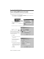
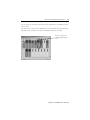
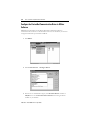
DeviceNet
Universal PCI
Scanner Card
1784-PCIDS Series B
Installation
Instructions
Important User Information
Solid state equipment has operational characteristics differing from those of electromechanical equipment.
Safety Guidelines for the Application, Installation and Maintenance of Solid State Controls (Publication
SGI-1.1 available from your local Rockwell Automation sales office or online at
http://www.ab.com/manuals/gi) describes some important differences between solid state equipment and
hard-wired electromechanical devices. Because of this difference, and also because of the wide variety of
uses for solid state equipment, all persons responsible for applying this equipment must satisfy themselves
that each intended application of this equipment is acceptable.
In no event will Rockwell Automation, Inc. be responsible or liable for indirect or consequential damages
resulting from the use or application of this equipment.
The examples and diagrams in this manual are included solely for illustrative purposes. Because of the many
variables and requirements associated with any particular installation, Rockwell Automation, Inc. cannot
assume responsibility or liability for actual use based on the examples and diagrams.
No patent liability is assumed by Rockwell Automation, Inc. with respect to use of information, circuits,
equipment, or software described in this manual.
Reproduction of the contents of this manual, in whole or in part, without written permission of Rockwell
Automation, Inc. is prohibited.
Throughout this manual, when necessary we use notes to make you aware of safety considerations.
WARNING
Identifies information about practices or circumstances that can cause an explosion in a
hazardous environment, which may lead to personal injury or death, property damage,
or economic loss.
IMPORTANT
Identifies information that is critical for successful application and understanding of the
product.
ATTENTION
Identifies information about practices or circumstances that can lead to personal injury
or death, property damage, or economic loss. Attentions help you:
• identify a hazard
• avoid a hazard
• recognize the consequence
SHOCK HAZARD
Labels may be located on or inside the equipment (e.g., drive or motor) to alert people
that dangerous voltage may be present.
BURN HAZARD
Labels may be located on or inside the equipment (e.g., drive or motor) to alert people
that surfaces may be dangerous temperatures.
ATTENTION
This equipment is intended for use in a Pollution Degree 2 industrial
environment, in overvoltage Category II applications (as defined in
IEC publication 60664-1), at altitudes up to 2000 meters without
derating.
This equipment is considered Group 1, Class A industrial equipment
according to IEC/CISPR Publication 11. Without appropriate
precautions, there may be potential difficulties ensuring
electromagnetic compatibility in other environments due to
conducted as well as radiated disturbance.
This equipment is supplied as “open type” equipment. It must be
mounted within an enclosure that is suitably designed for those
specific environmental conditions that will be present and
appropriately designed to prevent personal injury resulting from
accessibility to live parts. The interior of the enclosure must be
accessible only by the use of a tool. Subsequent sections of this
publication may contain additional information regarding specific
enclosure type ratings that are required to comply with certain
product safety certifications.
NOTE: See NEMA Standards publication 250 and IEC publication
60529, as applicable, for explanations of the degrees of protection
provided by different types of enclosure. Also, see the appropriate
sections in this publication, as well as the Allen-Bradley publication
1770-4.1 (“Industrial Automation Wiring and Grounding
Guidelines”), for additional installation requirements pertaining to
this equipment.
ATTENTION
Preventing Electrostatic Discharge
This equipment is sensitive to electrostatic discharge, which can cause
internal damage and affect normal operation. Follow these guidelines
when you handle this equipment:
•
•
•
•
•
•
Touch a grounded object to discharge potential static
Wear an approved grounding wriststrap
Do not touch connectors or pins on component boards
Do not touch circuit components inside the equipment
If available, use a static-safe workstation
When not in use, store the equipment in appropriate static-safe
packaging.
North American Hazardous Location Approval
The following information applies when operating
this equipment in hazardous locations:
Informations sur l’utilisation de cet équipement en
environnements dangereux:
Products marked “CL I, DIV 2, GP A, B, C, D” are suitable for
use in Class I Division 2 Groups A, B, C, D, Hazardous
Locations and nonhazardous locations only. Each product is
supplied with markings on the rating nameplate indicating
the hazardous location temperature code. When combining
products within a system, the most adverse temperature
code (lowest “T” number) may be used to help determine
the overall temperature code of the system. Combinations of
equipment in your system are subject to investigation by the
local Authority Having Jurisdiction at the time of
installation.
Les produits marqués "CL I, DIV 2, GP A, B, C, D" ne
conviennent qu’à une utilisation en environnements de
Classe I Division 2 Groupes A, B, C, D dangereux et non
dangereux. Chaque produit est livré avec des marquages
sur sa plaque d’identification qui indiquent le code de
température pour les environnements dangereux.
Lorsque plusieurs produits sont combinés dans un
système, le code de température le plus défavorable
(code de température le plus faible) peut être utilisé pour
déterminer le code de température global du système.
Les combinaisons d’équipements dans le système sont
sujettes à inspection par les autorités locales qualifiées
au moment de l’installation.
WARNING
EXPLOSION HAZARD
• Do not disconnect equipment
unless power has been
removed or the area is known
to be nonhazardous.
• Do not disconnect
connections to this
equipment unless power has
been removed or the area is
known to be nonhazardous.
Secure any external
connections that mate to this
equipment by using screws,
sliding latches, threaded
connectors, or other means
provided with this product.
• Substitution of components
may impair suitability for
Class I, Division 2.
• If this product contains
batteries, they must be
changed only in an area
known to be nonhazardous.
AVERTISSEMENT
RISQUE D’EXPLOSION
• Couper le courant ou
s’assurer que
l’environnement est
classé non dangereux
avant de débrancher
l'équipement.
• Couper le courant ou
s'assurer que
l’environnement est
classé non dangereux
avant de débrancher les
connecteurs. Fixer tous
les connecteurs externes
reliés à cet équipement à
l'aide de vis, loquets
coulissants, connecteurs
filetés ou autres moyens
fournis avec ce produit.
• La substitution de
composants peut rendre
cet équipement inadapté
à une utilisation en
environnement de Classe
I, Division 2.
• S’assurer que
l’environnement est
classé non dangereux
avant de changer les
piles.
Preface
About the 1784-PCIDS Universal PCI Scanner Card
For Information On This Topic
Refer To Page
What is a 1784-PCIDS Universal PCI Scanner Card?
1
Purpose of This Manual
1
Intended Audience
1
System Requirements
1
What Your Package Contains
2
For Further Reference
2
What is a 1784-PCIDS Universal PCI Scanner Card?
The 1784-PCIDS Universal PCI Scanner Card is a Universal Peripheral Component
Interconnect (PCI) open-bus interface card that provides DeviceNet monitoring,
configuration, explicit messaging and I/O scan capabilities.
Purpose of This Manual
Use this document to learn how to install and use the 1784-PCIDS DeviceNet Universal PCI
Scanner Card.
Intended Audience
Read this manual before you install or use the 1784-PCIDS Universal PCI Scanner Card. You
should be familiar with DeviceNet technology when applying products such as those
described in this publication.
System Requirements
You must use a Separated Extra Low Voltage (SELV) or a Protected Extra Low Voltage
(PELV) power supply to comply with CE Low Voltage Directives.
In North America, use a UL listed or CSA Certified computer chassis. The DeviceNet
network must use a UL listed or CSA Certified Class 2 power supply.
Publication 1784-IN004E-EN-P - April 2005
2
Preface
What Your Package Contains
With this package you should receive:
•
•
•
•
one 1784-PCIDS card
one terminal block connector
one IOLinx 1784-PCIDS driver CD-ROM
DeviceNet Universal PCI Scanner Card Installation Instructions, publication
1784-IN004
For Further Reference
Refer to these publications for more information on installing and using your 1784-PCIDS
card:
Publication Number
Publication Title
DNET-UM004
DeviceNet Modules in Logix5000 Control Systems User Manual
1789-UM002
SoftLogix5800 System User Manual
DNET-UM072
DeviceNet Media Design and Installation Guide
9230-IOLINX SDK
IOLinx Software Development Kit
Publication 1784-IN004E-EN-P - April 2005
Table of Contents
Chapter 1
Install IOLinx
Uninstall the Previous Version of IOLinx . . . . . . . . . . . . . . . . . . . . . . . . . 1-1
Install IOLinx . . . . . . . . . . . . . . . . . . . . . . . . . . . . . . . . . . . . . . . . . . . . . . . . 1-3
Chapter 2
Install the 1784-PCIDS Card
Before You Begin. . . . . . . . . . . . . . . . . . . . . . . . . . . . . . . . . . . . . . . . . . . . .
Access the Computer’s PCI Local Bus Expansion Slots . . . . . . . . . . . . . .
Insert the Card Into the Computer . . . . . . . . . . . . . . . . . . . . . . . . . . . . . . .
Connect to the Network . . . . . . . . . . . . . . . . . . . . . . . . . . . . . . . . . . . . . . .
What Is Next?. . . . . . . . . . . . . . . . . . . . . . . . . . . . . . . . . . . . . . . . . . . . . . . .
2-1
2-2
2-3
2-3
2-4
Chapter 3
Install the 1784-PCIDS Driver in Windows XP
Install the Driver in Windows XP For the First Time . . . . . . . . . . . . . . . . 3-2
Update the Existing Driver in Windows XP . . . . . . . . . . . . . . . . . . . . . . . 3-4
Chapter 4
Install the 1784-PCIDS Driver In Windows 2000
Install the Driver in Windows 2000 For the First Time . . . . . . . . . . . . . . 4-1
Update the Existing Driver in Windows 2000 . . . . . . . . . . . . . . . . . . . . . . 4-4
Chapter 5
Once You Have Completed the Installation
Register the EDS File. . . . . . . . . . . . . . . . . . . . . . . . . . . . . . . . . . . . . . . . . .
Connect a SoftLogix5800 Controller to DeviceNet. . . . . . . . . . . . . . . . . .
Configure the DeviceNet Communication Driver in RSLinx Software . .
Configure the Scan List . . . . . . . . . . . . . . . . . . . . . . . . . . . . . . . . . . . . . . . .
5-1
5-2
5-4
5-7
Publication 1784-IN004E-EN-P - April 2005
ii
Table of Contents
Chapter 6
Use the DeviceNet Test Application to Verify the Configuration
Before You Begin. . . . . . . . . . . . . . . . . . . . . . . . . . . . . . . . . . . . . . . . . . . . .
Start the Test Application . . . . . . . . . . . . . . . . . . . . . . . . . . . . . . . . . . . . . .
Configure the Port . . . . . . . . . . . . . . . . . . . . . . . . . . . . . . . . . . . . . . . . . . . .
Create a View . . . . . . . . . . . . . . . . . . . . . . . . . . . . . . . . . . . . . . . . . . . . . . . .
Read Inputs . . . . . . . . . . . . . . . . . . . . . . . . . . . . . . . . . . . . . . . . . . . . . . . . .
Write Outputs. . . . . . . . . . . . . . . . . . . . . . . . . . . . . . . . . . . . . . . . . . . . . . . .
Change the Scanner Mode . . . . . . . . . . . . . . . . . . . . . . . . . . . . . . . . . . . . . .
Use the Device Status Screen . . . . . . . . . . . . . . . . . . . . . . . . . . . . . . . . . . .
6-1
6-2
6-2
6-3
6-4
6-4
6-5
6-5
Chapter 7
Interpret Status Indicators (LEDs)
I/O Status Indicator . . . . . . . . . . . . . . . . . . . . . . . . . . . . . . . . . . . . . . . . . . 7-3
Module (MOD) Status Indicator . . . . . . . . . . . . . . . . . . . . . . . . . . . . . . . . . 7-4
Network (NET) Status Indicator . . . . . . . . . . . . . . . . . . . . . . . . . . . . . . . . 7-5
Appendix A
Specifications
Index
Publication 1784-IN004E-EN-P - April 2005
Chapter
1
Install IOLinx
For Information On This Topic
Refer To Page
Uninstall the Previous Version of IOLinx
1-1
Install IOLinx
1-3
Uninstall the Previous Version of IOLinx
IMPORTANT
Before you update the new Driver and IOLinx, you must uninstall any
earlier versions of IOLinx. If you do not currently have IOLinx installed,
go to the Install IOLinx procedure on page 1-3.
1. Shut down all applications that use the IOLinx DeviceNet Driver, including RSLinx
and SoftLogix.
In This Operating System
Select
Windows 2000
Start ⇒Settings ⇒Control Panel, then double-click the
Add/Remove Programs icon
Windows XP
Start ⇒Control Panel ⇒Add or Remove Programs, or
Start ⇒Control Panel, then double-click the Add or Remove
Programs icon
Publication 1784-IN004E-EN-P - April 2005
1-2
Install IOLinx
2. Depending on which previous version of IOLinx was installed, click on one of the
following to remove it:
• IOLinx for DeviceNet
• 1784-PCIDS Drivers for IOLinx
• IOLinx for the 1784-PCIDS Card
3. Select Remove.
4. Select Yes to uninstall IOLinx.
TIP
If you are prompted to remove unused shared files, select No to All.
5. Reboot the computer.
Publication 1784-IN004E-EN-P - April 2005
Install IOLinx
1-3
Install IOLinx
IMPORTANT
TIP
We recommend that you exit all Windows programs before running this
Setup program.
The CD-ROM supports Windows Autorun. If you have Autorun
configured, once the CD is inserted into the CD-ROM drive, the
installation will automatically start at the first setup screen.
1. Insert the CD in the computer’s CD-ROM drive or access the compressed file you
downloaded and saved to a temporary directory.
2. If you are installing from CD-ROM and Autorun is enabled for your CD-ROM drive,
go to step 5 on page 1-4.
3. Select Start ⇒Run.
4. At the Run pop-up screen, type x:\setup where x is the drive where the installation
files are stored and click OK.
Publication 1784-IN004E-EN-P - April 2005
1-4
Install IOLinx
5. Select Install IOLinx for DeviceNet.
You see the IOLinx for DeviceNet Setup Wizard screen.
6. Click Next.
Publication 1784-IN004E-EN-P - April 2005
Install IOLinx
1-5
You see the Select Installation Folder screen.
7. Use the default path to the folder. Select the Everyone or Just me radio button,
depending on your application.
8. Click Next. You see the Confirm Installation screen.
9. Click Next to install IOLinx.
10. After the installation is complete, you see the Installation Complete screen. Click
Close.
Publication 1784-IN004E-EN-P - April 2005
1-6
Install IOLinx
Notes:
Publication 1784-IN004E-EN-P - April 2005
Chapter
2
Install the 1784-PCIDS Card
For Information On This Topic
Refer To Page
Before You Begin
2-1
Access the Computer’s PCI Local Bus Expansion Slots
2-2
Insert the Card Into the Computer
2-3
Connect to the Network
2-3
Before You Begin
WARNING
If you connect or disconnect the communications cable with power
applied to this module or any device on the network, an electrical arc
can occur. This could cause an explosion in hazardous location
installations.
When used in a Class I, Division 2, hazardous location, this
equipment must be mounted in a suitable enclosure with proper
wiring method that complies with the governing electrical codes.
If you insert or remove the card while host power is on, an electrical
arc can occur. This could cause an explosion in hazardous location
installations.
Be sure that power is removed or the area is nonhazardous before
proceeding.
Publication 1784-IN004E-EN-P - April 2005
2-2
Install the 1784-PCIDS Card
To install the card, you need to:
• access the computer’s expansion slots
• insert the card into the computer
IMPORTANT
The card’s dimensions are shown below.
4.72 in. (12 cm)
4.2 in.
(10.7 cm)
31536-M
Access the Computer’s PCI Local Bus Expansion Slots
To install the card, you must access the computer’s PCI local bus expansion slots. Follow
these general steps, or refer to your computer’s user guide for further instructions:
1. Shut down the host computer.
2. Remove the computer’s cover.
3. Select a vacant PCI local bus expansion slot.
4. Loosen the screw (if present) on the back (rear bracket) of the computer.
5. Remove the slot’s expansion cover.
Publication 1784-IN004E-EN-P - April 2005
Install the 1784-PCIDS Card
2-3
Insert the Card Into the Computer
To insert the card inside the computer:
1. Handle the card so that you prevent electrostatic discharge.
Refer to the Preface of this manual for more information.
2. Insert the card into the edge connector and tighten the expansion slot screw (if
present).
3. Replace the computer’s cover.
4. Turn on the computer to be certain that it comes up correctly.
If The Computer
Then
powers up
go to the next section, Connect to the Network, on page 2-3
hangs up
either the card is not seated correctly in the PCI slot or you have a
memory or I/O conflict. You should:
• remove and reinsert the card into the same PCI slot and
try again
• remove and reinsert the card into a different PCI slot and
try again
• remove all other non-essential cards and try again
If you continue to experience difficulty, contact your local
Rockwell Automation sales representative or distributor, or call
Rockwell Automation Technical Support at 440.646.5800.
Connect to the Network
WARNING
If you connect or disconnect the DeviceNet cable with power applied
to this module or any device on the network, an electrical arc can
occur. This could cause an explosion in hazardous location
installations. Be sure that power is removed or the area is
nonhazardous before proceeding.
Figure 2.1 and the table which follows it show the necessary network connections you make
to the card. The label (on the card’s metal retaining bracket) is color-coded for easy wiring.
Publication 1784-IN004E-EN-P - April 2005
2-4
Install the 1784-PCIDS Card
Figure 2.1 Wiring the Card
30139-M
Pin Number
Wire Color
Abbreviation
Description
1
black
V-
24V dc power return
2
blue
CAN_L
data low - data line
3
bare
DRAIN
shield
4
white
CAN_H
data high - data line
5
red
V+
+24V dc
For detailed wiring information, refer to the DeviceNet Media Design and Installation Guide,
publication DNET-UM072.
What Is Next?
In This Operating System:
Do This:
Windows XP
go on to Chapter 3 to install the driver
Windows 2000
go on to Chapter 4 to install the driver
Publication 1784-IN004E-EN-P - April 2005
Chapter
3
Install the 1784-PCIDS Driver in Windows XP
For Information On This Topic
Refer To Page
Install the Driver in Windows XP For the First Time
3-2
Update the Existing Driver in Windows XP
3-4
IMPORTANT
Be sure that your 1784-PCIDS card is properly installed. Refer to
Chapters 1 and 2 of this manual to install the card.
Publication 1784-IN004E-EN-P - April 2005
3-2
Install the 1784-PCIDS Driver in Windows XP
Install the Driver in Windows XP For the First Time
IMPORTANT
Use this procedure only if this is the first time that you are installing the
1784-PCIDS driver and IOLinx on this computer. Otherwise, use the
Update the Existing Driver in Windows XP procedure on page 3-4
instead of this procedure.
1. When you boot up your computer for the first time after installing your 1784-PCIDS
card, you see the Found New Hardware Wizard screen.
2. Click on the Install from a list or specific location (Advanced) radio button.
3. Click Next.
Publication 1784-IN004E-EN-P - April 2005
Install the 1784-PCIDS Driver in Windows XP
3-3
4. Click the Search for the best driver in these locations radio button.
5. Select the Include this location in the search checkbox and uncheck the remaining
checkboxes.
6. In the Found New Hardware Wizard, click Browse and browse to this location:
x:\Program Files\Rockwell Software\IOLinx\IOLinx for DeviceNet\Drivers
where x is the drive where IOLinx is installed.
Publication 1784-IN004E-EN-P - April 2005
3-4
Install the 1784-PCIDS Driver in Windows XP
7. Click OK.
8. Click Next to install the drivers.
9. Click Finish.
10. Shut down and re-start the PC. The driver is now ready to use. Go on to Chapter 5.
Update the Existing Driver in Windows XP
Use this procedure only if you have previously installed the 1784-PCIDS
driver and IOLinx on this computer. If you have not previously installed
the 1784-PCIDS driver and IOLinx on this computer, use the Install the
Driver in Windows XP For the First Time procedure on page 3-2 instead
of this procedure.
IMPORTANT
IMPORTANT
During the update procedure, communication through the card will be
disrupted.
1. Select Start.
2. Right-click on My Computer.
Publication 1784-IN004E-EN-P - April 2005
Install the 1784-PCIDS Driver in Windows XP
3-5
3. Select Manage.
4. On the Computer Management screen that appears, select Device Manager.
If This Driver Version Was Installed
Then
1.14 or earlier
go to step 5 on page 3-6
1.15 or later
go to step 6 on page 3-6
Publication 1784-IN004E-EN-P - April 2005
3-6
Install the 1784-PCIDS Driver in Windows XP
5. If driver version 1.14 or earlier was installed, follow this procedure:
a. Click on Other Devices to expand the list.
Click on Other Devices to
expand it. Then right-click
on Network Controller.
b. Right-click on the Network Controller that corresponds to the 1784-PCIDS card
that you are updating and select Properties.
TIP
If you see more than one 1784-PCIDS entry, perform the update on
only one of the entries.
c. Go to step 7.
6. If driver version 1.15 or later was installed, follow this procedure:
a. Click on Allen-Bradley PCI Family to expand the list.
Click on Allen-Bradley PCI
Family to expand it. Then
right-click on Allen-Bradley
1784-PCIDS.
Publication 1784-IN004E-EN-P - April 2005
Install the 1784-PCIDS Driver in Windows XP
3-7
b. Right-click on the Allen-Bradley 1784-PCIDS that corresponds to the
1784-PCIDS card you are updating and select Properties.
TIP
If you see more than one 1784-PCIDS entry, perform the update on
only one of the entries.
7. Click on the Driver tab, then click Update Driver.
You see the Hardware Update Wizard.
8. Select the Install from a list or specific location (Advanced) radio button.
9. Click Next.
Publication 1784-IN004E-EN-P - April 2005
3-8
Install the 1784-PCIDS Driver in Windows XP
10. Click the Don't search. I will choose the driver to install radio button.
11. Click Next.
12. Click the Have Disk... button.
Publication 1784-IN004E-EN-P - April 2005
Install the 1784-PCIDS Driver in Windows XP
3-9
13. Click Browse and browse to this location:
x:\Program Files\Rockwell Software\IOLinx\IOLinx for DeviceNet\Drivers
where x is the drive where IOLinx is installed.
14. Click Open.
15. Click OK.
16. Click Allen-Bradley 1784-PCIDS to highlight it.
17. Click Next.
18. Click Finish.
19. Shut down and re-start the PC.
The driver is now ready to use. Go on to Chapter 5.
Publication 1784-IN004E-EN-P - April 2005
3-10
Install the 1784-PCIDS Driver in Windows XP
Notes:
Publication 1784-IN004E-EN-P - April 2005
Chapter
4
Install the 1784-PCIDS Driver In Windows 2000
For Information On This Topic
Refer To Page
Install the Driver in Windows 2000 For the First Time
4-1
Update the Existing Driver in Windows 2000
4-4
IMPORTANT
Be sure that your 1784-PCIDS card is properly installed. Refer to
Chapters 1 and 2 of this manual to install the card.
Install the Driver in Windows 2000 For the First Time
IMPORTANT
Use this procedure only if this is the first time that you are installing the
1784-PCIDS driver and IOLinx on this computer. Otherwise, use the
Update the Existing Driver in Windows 2000 procedure on page 4-4
instead of this procedure.
Publication 1784-IN004E-EN-P - April 2005
4-2
Install the 1784-PCIDS Driver In Windows 2000
1. When you boot up your computer for the first time after installing your 1784-PCIDS
card, you see the Found New Hardware Wizard screen.
2. Click Next.
3. Click on Search for a suitable driver for my device (recommended).
4. Click Next.
Publication 1784-IN004E-EN-P - April 2005
Install the 1784-PCIDS Driver In Windows 2000
4-3
5. Select Specify a Location.
6. Click Next.
7. In the Found New Hardware Wizard, click Browse and browse to this location:
x:\Program Files\Rockwell Software\IOLinx\IOLinx for DeviceNet
\Drivers\abpcids.inf
where x is the drive where IOLinx is installed.
8. Click Open.
9. Click OK.
10. Click Next to install the new driver.
11. Click Finish.
12. Shut down and re-start the PC.
The driver is now ready to use. Go on to Chapter 5.
Publication 1784-IN004E-EN-P - April 2005
4-4
Install the 1784-PCIDS Driver In Windows 2000
Update the Existing Driver in Windows 2000
IMPORTANT
IMPORTANT
Use this procedure only if you have previously installed the 1784-PCIDS
driver and IOLinx on this computer. If you have not previously installed
the 1784-PCIDS driver and IOLinx on this computer, use the Install the
Driver in Windows 2000 For the First Time procedure on page 4-1
instead of this procedure.
During the update procedure, communication through the card will be
disrupted.
1. Right-click on My Computer.
2. Select Manage.
3. On the Computer Management screen that appears, select Device Manager.
If
Then
driver version 1.14 or earlier was installed
go to step 4 on page 4-5
driver version 1.15 or later was installed
go to step 5 on page 4-6
Publication 1784-IN004E-EN-P - April 2005
Install the 1784-PCIDS Driver In Windows 2000
4-5
4. If driver version 1.14 or earlier was installed, follow this procedure:
a. Click on Other Devices to expand the list.
Click on Other Devices
to expand it. Then
right-click on Network
Controller.
b. Right-click on the Network Controller that corresponds to the 1784-PCIDS card
that you are updating and select Properties.1784-
TIP
If you see more than one 1784-PCIDS entry, perform the update on
only one of the entries.
c. Go to step 6.
Publication 1784-IN004E-EN-P - April 2005
4-6
Install the 1784-PCIDS Driver In Windows 2000
5. If driver version 1.15 or later was installed, follow this procedure:
a. Click on Allen-Bradley PCI Family to expand the list.
Click on Allen-Bradley
PCI Family to expand it.
Then right-click on
Allen-Bradley
1784-PCIDS.
b. Right-click on the Allen-Bradley 1784-PCIDS that corresponds to the PCIDS
card you are updating and select Properties.
TIP
If you see more than one 1784-PCIDS entry, perform the update on
only one of the entries.
6. Click on the Driver tab, then click Update Driver.
You see the Upgrade Device Driver Wizard screen.
7. Click Next.
Publication 1784-IN004E-EN-P - April 2005
Install the 1784-PCIDS Driver In Windows 2000
4-7
8. Select the Display a list of known drivers for this device so that I can choose a
specific driver radio button.
9. Click Next.
10. Click the Have Disk... button.
Publication 1784-IN004E-EN-P - April 2005
4-8
Install the 1784-PCIDS Driver In Windows 2000
11. Click Browse and browse to this location:
x:\Program Files\Rockwell Software\IOLinx\IOLinx for DeviceNet
\Drivers\abpcids.inf
where x:\ is the drive where IOLinx is installed.
12. Click Open.
13. Click OK.
14. Click Allen-Bradley 1784-PCIDS to highlight it.
15. Click Next.
16. Click Next.
17. Click Finish.
18. Close the Allen-Bradley 1784-PCIDS Properties screen.
19. Close the Device Manager screen.
20. Shut down and re-start the PC.
21. The driver is now ready to use.
Go on to Chapter 5.
Publication 1784-IN004E-EN-P - April 2005
Chapter
5
Once You Have Completed the Installation
Once you have installed the card and driver, you can do the following:
For Information On This Topic
Refer To Page
Register the EDS File
5-1
Connect a SoftLogix5800 Controller to DeviceNet
5-2
Configure the DeviceNet Communication Driver in RSLinx
Software
5-4
Configure the Scan List
5-7
Register the EDS File
You can find the EDS file in the \EDS Files folder on the 1784-PCIDS Driver CD-ROM or
download it from http://www.ab.com/networks/eds/.
Use the EDS wizard in either RSLinx or RSNetWorx for DeviceNet software to register the
EDS file (0001000C00300300.eds) for the 1784-PCIDS card.
• In Windows, select Start ⇒Programs ⇒Rockwell Software ⇒RSLinx Tools
⇒EDS Hardware Installation Tool.
• In RSNetWorx for DeviceNet, select Tools ⇒EDS Wizard....
Publication 1784-IN004E-EN-P - April 2005
5-2
Once You Have Completed the Installation
Connect a SoftLogix5800 Controller to DeviceNet
Before you can connect the SoftLogix system to the DeviceNet network, you must create the
1784-PCIDS card as part of the SoftLogix chassis.
1. From the SoftLogix chassis monitor, select Slot ⇒Create Module or right-click the appropriate slot
and select Create. Select the 1784-PCIDS card.
2. Specify
the backplane slot number.
3. Click OK.
4. Select the serial number of the 1784-PCIDS card you want.
5. Select the serial number of the
card.
If you previously configured the 1784-PCIDS
card that you selected by serial number, the
chassis monitor remembers the configuration
from the last time you used the card (whether
in the same or a different slot).
6. Click Next.
7. Specify configuration settings for the
1784-PCIDS card:
A. Specify the network address (MAC
ID) on the DeviceNet network.
B. Specify the baud rate.
C. Enter the label name for the card (this
is the name you wrote on the label of
the card to help you identify the card
when you have others in the same
computer).
8. Click Finish.
Publication 1784-IN004E-EN-P - April 2005
Once You Have Completed the Installation
5-3
You can specify any slot number greater than 0 for the communication card. RSLinx software
resides in slot 0.
The chassis monitor shows the 1784-PCIDS card as a virtual module in the SoftLogix chassis.
The LEDs on the virtual monitor emulate a 1756-DNB communication module.
This chassis monitor has a
1784-PCIDS card installed in
slot 5.
Publication 1784-IN004E-EN-P - April 2005
5-4
Once You Have Completed the Installation
Configure the DeviceNet Communication Driver in RSLinx
Software
RSNetWorx for DeviceNet uses the RSLinx DeviceNet communication driver to
communicate with the devices on the DeviceNet network. To use this driver you must first
configure the DeviceNet port and driver in RSLinx.
1. Start RSLinx.
2. Select Communications ⇒Configure Drivers.
3. From the list of Available Driver Types, select DeviceNet Drivers and click on
Add/New. You see the DeviceNet Driver Selection screen listing the drivers
available on your machine.
Publication 1784-IN004E-EN-P - April 2005
Once You Have Completed the Installation
5-5
4. Highlight the Allen-Bradley 1784-PCIDS driver and click on Select. The
1784-PCIDS Driver Configuration screen opens.
If you have configured the
driver with SoftLogix5800
Chassis Monitor, these two
fields appear grayed out.
5. In the DeviceNet Port Setup area of the Driver Configuration screen, set the Node
Address and Network Baud Rate (we used Node Address 1 and a Baud Rate of 500K
for the example network).
TIP
If you have configured the driver with SoftLogix5800 Chassis
Monitor, the Node Address and Network Baud Rate fields appear
grayed out. You cannot change the node address or network baud
rates on this screen.
6. Click OK.
Publication 1784-IN004E-EN-P - April 2005
5-6
Once You Have Completed the Installation
7. Enter a name for the new RSLinx driver and click OK.
The new driver will be added to the list of configured RSLinx drivers. (Your screen
will display the drivers you have configured on your system.)
TIP
Browse the network by expanding the DeviceNet port on the desired
1784-PCIDS communication card.
The driver’s Status should be
“Running”. If not, there is a
problem. Check the physical
connection to the 1784-PCIDS
card. If the physical connection is
intact, verify the network baud
rate and ensure that the
1784-PCIDS card’s node number is
unique. Also check the external
24V power connections. The
Network LED on the 1784-PCIDS
card should be solid or flashing
green when the card is connected to
the DeviceNet network.
Publication 1784-IN004E-EN-P - April 2005
Once You Have Completed the Installation
5-7
Configure the Scan List
Use RSNetWorx for DeviceNet to configure the scan list for the 1784-PCIDS card. Refer to
the following publications for details.
Publication Number
Publication Title
DNET-UM004
DeviceNet Modules in Logix5000 Control Systems User Manual
1789-UM002
SoftLogix5800 System User Manual
Publication 1784-IN004E-EN-P - April 2005
5-8
Once You Have Completed the Installation
Notes:
.
Publication 1784-IN004E-EN-P - April 2005
Chapter
6
Use the DeviceNet Test Application to Verify the
Configuration
For Information On This Topic
Refer To Page
Before You Begin
6-1
Start the Test Application
6-2
Configure the Port
6-2
Create a View
6-3
Change the Scanner Mode
6-5
Read Inputs
6-4
Write Outputs
6-4
Change the Scanner Mode
6-5
Included with the IOLinx for 1784-PCIDS driver CD is a stand-alone test application (called
DNetTest.exe) that lets you diagnose simple problems over the network before the control
application is available for integration.
In addition, you can use the application to make certain that the 1784-PCIDS card has been
correctly installed and is functioning in the PC.
Before You Begin
Before you begin, you must have done the following:
• Installed the card
• Connected it to the DeviceNet network, and
• Used RSNetWorx for DeviceNet to load a scan list into the card
Publication 1784-IN004E-EN-P - April 2005
6-2
Use the DeviceNet Test Application to Verify the Configuration
Start the Test Application
The test application is automatically installed as part of the driver installation procedure.
To start the test application, click Start ⇒Programs ⇒Rockwell Software ⇒IOLinx
⇒IOLinx for DeviceNet ⇒DeviceNet Test.
If the driver cannot establish communication with the module, an error message is displayed.
Configure the Port
You must configure the port the first time you use a 1784-PCIDS card.
To configure the port, follow these steps:
1. Select Configure Port... from the Setup menu.
2. Select Allen-Bradley 1784-PCIDS from the DeviceNet Driver Selection screen.
3. Click on Select.
4. Set Node Address (0 - 63).
5. Set Baud Rate (125/250/500 kbs).
6. Click OK. You see a dialog box that tells you operation was successful, followed by a
similar message box that tells you that the port has been configured.
Publication 1784-IN004E-EN-P - April 2005
Use the DeviceNet Test Application to Verify the Configuration
6-3
Create a View
To go online and create a view, follow these steps:
1. From the Setup menu, select Create View.... You see the View Creation Parameters
screen.
2. Select the port name corresponding to the port for which you are creating the view.
3. Select the message type (input, output, or input/output) that you want to use for the
view you are creating.
4. Select the privilege (read only, read/write) that you want to use for the view that you
are creating.
5. If you want to use the Watchdog timer for the view you are creating, check the
Enabled checkbox and enter the watchdog timeout value (in milliseconds) that you
want to use.
6. Click OK. You see a dialog box that tells you that the operation was successful.
Publication 1784-IN004E-EN-P - April 2005
6-4
Use the DeviceNet Test Application to Verify the Configuration
Read Inputs
The DeviceNet Test Application lets you read as many as 2048 bytes from the input image
table of the 1784-PCIDS card. A simple screen (shown in the following figure) is displayed
and is automatically updated when inputs change.
TIP
The hexadecimal number on the left side of the input or output table
is the count in bytes.
This
hexadecimal
number is the
count in bytes.
Write Outputs
The DeviceNet Test Application lets you write as many as 2048 bytes to the output image
table of the scanner.
1. On the I/O tab, select the desired byte(s) in the Output Image Table.
2. Type the desired value(s) in the New Value field.
3. Click the Write button. The data transfer is performed.
Publication 1784-IN004E-EN-P - April 2005
Use the DeviceNet Test Application to Verify the Configuration
6-5
Change the Scanner Mode
The Port Mode window displays the current mode of the scanner: Run, Idle, No View.
When the view is initially created, the scanner mode is set to Idle. The view state must be set
to Run in order for the I/O devices to energize their outputs based on the output data from
the scanner.
ATTENTION
Changing the view state to Run will cause the I/O devices to energize
their outputs based on the output data from the scanner.
To avoid personal injury and property damage, before setting the view
state to Run, verify that the output values are appropriate for the I/O
devices.
Use the Switch Mode button to change the mode between Run and Idle. Once the mode is
set to Run, active outputs are sent to the associated I/O devices.
Use the Device Status Screen
The Device Status screen displays an Idle/Failure Table where you can double-click on a
node to see its status, for example, MAC ID, status code, and status messages such as ‘device
stopped communicating’.
If you double-click on an empty node, you see this response:
OK or not in scan list.
Publication 1784-IN004E-EN-P - April 2005
6-6
Use the DeviceNet Test Application to Verify the Configuration
Notes:
Publication 1784-IN004E-EN-P - April 2005
Use the DeviceNet Test Application to Verify the Configuration
6-7
Publication 1784-IN004E-EN-P - April 2005
6-8
Use the DeviceNet Test Application to Verify the Configuration
Publication 1784-IN004E-EN-P - April 2005
Chapter
7
Interpret Status Indicators (LEDs)
For Information On This Topic
Refer To Page
I/O Status Indicator
7-3
Module (MOD) Status Indicator
7-4
Network (NET) Status Indicator
7-5
The three status indicators on the 1784-PCIDS card provide information about the
DeviceNet network and its connections. See Figure 7.1 for an illustration of the status
indicators.
Publication 1784-IN004E-EN-P - April 2005
7-2
Interpret Status Indicators (LEDs)
Figure 7.1 Status Indicators
S
Allen-Bradley
1784-PCIDS
Scanner
I/O
I/O Status
MOD NET
Network Status
Module Status
The tables on pages 7-3 through 7-5 outline the indicator condition and the corresponding
status, and explain what each condition means to you.
Publication 1784-IN004E-EN-P - April 2005
Interpret Status Indicators (LEDs)
7-3
I/O Status Indicator
This bi-color (green/red) LED provides information concerning the states of inputs and/or
outputs.
Condition
Status
Indicates
off
output(s) inactive
All Outputs are inactive.
input(s) inactive
All inputs are inactive.
output(s) active
One or more outputs are active and under control,
and no outputs are faulted.
input(s) active
One or more inputs are active and producing data,
and no inputs are faulted.
flashing green1
output(s) idle
One or more outputs are idle and no outputs are
active or faulted.
flashing red1
output(s) faulted
One or more outputs are faulted, and may be in
the fault state.
input(s) faulted
One or more inputs are faulted, and may be in the
fault state.
output(s) forced off
One or more outputs are forced off (may be an
unrecoverable fault).
input unrecoverable fault
One or more inputs has an unrecoverable fault.
green
red
1 The flash rate of the LED is approximately 1 flash per second. The LED should be on for approximately
0.5 seconds and off for approximately 0.5 seconds.
Publication 1784-IN004E-EN-P - April 2005
7-4
Interpret Status Indicators (LEDs)
Module (MOD) Status Indicator
This bi-color (green/red) LED provides device status. It indicates whether or not the device
has power and is operating properly.
Condition
Status
Indicates
off
no power
No power applied to device.
device operational
Device is operating in a normal condition.
device in standby
(device needs
commissioning)
Device needs commissioning due to
configuration missing, incomplete, or
incorrect.
green
1
flashing green
Device may be in the standby state. Refer
to the DeviceNet Specification, Volume
II, Identity Object.
flashing red1
recoverable fault
e.g., the device’s scan list configuration
does not match the actual network
configuration.
red
unrecoverable fault
Device has an unrecoverable fault. Cycle
power to the card by shutting down and
cycling power to your computer. If the
problem persists, the device may need to
be replaced.
flashing red-green
device self testing
Device is in self test. Refer to the
DeviceNet Specification, Volume II,
Identity Object.
1
The flash rate of the LED is approximately 1 flash per second. The LED should be on for approximately
0.5 seconds and off for approximately 0.5 seconds.
Publication 1784-IN004E-EN-P - April 2005
Interpret Status Indicators (LEDs)
7-5
Network (NET) Status Indicator
This bi-color (green/red) LED indicates the status of the communication link.
condition
status
indicates
off
not powered,
Device is not online.
not online
The device has not completed the Dup_MAC_ID test yet.
The device may not be powered; look at the Module Status
LED.
flashing green1
online,
Device is online, but has no connections in the established
state.
not connected
The device has passed the Dup_MAC_ID test, is online, but
has no established connections to other nodes.
green
link okay, online,
connected
The device is online and has connections in the established
state.
flashing red1
connection time-out
One or more I/O connections are in the timed-out state.
red
critical link failure
Failed communication device. The device has detected an
error that has rendered it incapable of communicating on
the network (Duplicate MAC ID or Bus-off).
Check network integrity and baud rate of all devices. Then
cycle power to the card by shutting down and cycling power
to your computer.
1
The flash rate of the LED is approximately 1 flash per second. The LED should be on for approximately
0.5 seconds and off for approximately 0.5 seconds.
Publication 1784-IN004E-EN-P - April 2005
7-6
Interpret Status Indicators (LEDs)
Notes:
Publication 1784-IN004E-EN-P - April 2005
Appendix
A
Specifications
PCI local bus
compliant to PCI Rev. 2.2.
The 1784-PCIDS card is compatible with 5V and 3.3V PCI slots,
32-bit and 64-bit PCI slots, and PCI-X slots.
Attention: The 1784-PCIDS is not compatible with PCI Express and
should not be inserted into a PCI Express slot.
mechanical form factor
Universal PCI 32-bit short card
4.2 in. (10.7 cm) H x 4.72 in. (12 cm) L
host PC requirements
One of the following operating systems:
• Microsoft Windows XP with Service Pack 1 or higher
• Microsoft Windows 2000 with Service Pack 4 or higher
Microsoft Windows NT 4.0 is not supported.
capacity
2048 bytes of input image table
2048 bytes of output image table
software compatibility
Rockwell Software RSLinx 2.42.00 or later
Rockwell Software RSNetWorx for DeviceNet 2.11.51 or later
operational temperature
IEC 60068-2-1 (Test Ad, Operating Cold),
IEC 60068-2-2 (Test Bd, Operating Dry Heat),
IEC 60068-2-14 (Test Nb, Operating Thermal Shock):
0 to 55 °C (32 to 131 °F)
The operating parameters describe the environment within the PCI
slot. Refer to the documentation for your computer for
environmental requirements. This card should not exceed those
specifications.
storage temperature
IEC 60068-2-1 (Test Ab, Un-packaged Non-operating Cold),
IEC 60068-2-2 (Test Bb, Un-packaged Non-operating Dry Heat),
IEC 60068-2-14 (Test Na, Un-packaged Non-operating Thermal
Shock):
-40 to 85 °C (-40 to 185 °F)
relative humidity
IEC 60068-2-30 (Test Db, Un-packaged Non-operating Damp Heat):
5 to 95% non-condensing
vibration
IEC 60068-2-6 (Test Fc, Operating):
2g @ 10-500Hz
operating shock
IEC 60068-2-27 (Test Ea, Unpackaged Shock):
30g
Publication 1784-IN004E-EN-P - April 2005
A-2
Specifications
non-operating shock
IEC 60068-2-27 (Test Ea, Unpackaged Shock):
50g
emissions
CISPR 11:
Group 1, Class A
ESD immunity
IEC 61000-4-2:
6kV contact discharges
8kV air discharges
radiated RF immunity
IEC 61000-4-3:
10V/m with 1kHz sine-wave 80%AM from 80MHz to 2000MHz
10V/m with 200Hz 50% pulse 100%AM at 900MHz
10V/m with 200Hz 50% pulse 100%AM at 1890MHz
EFT/B immunity
IEC 61000-4-4:
+/-2kV at 5kHz on communications ports
surge transient immunity
IEC 61000-4-5:
+/-2kV line-earth (CM) on communications ports
conducted RF immunity
IEC 61000-4-6:
10Vrms with 1kHz sine-wave 80% AM from 150kHz to 80MHz
enclosure type rating
none (open-style)
power requirements
In US, this equipment must be powered from UL Listed Information
Technology Equipment or UL Listed Industrial Control Equipment. In
Canada, this equipment must be powered by an SELV source, CSA
Certified Information Technology Equipment, or CSA Certified
Process Control Equipment.
PC: 5V dc, 700mA maximum, Class 2.
The DeviceNet power supply must be compliant with the
requirements for Class 2 as defined in NFPA-70, National Electrical
Code and/or CSA C22.1, Canadian Electrical Code, Part 1.
DeviceNet: +24V dc @90 mA max. Class 2
power dissipation
3.5W
isolation voltage (continuous-voltage
withstand rating)
50V continuous
Tested to withstand 500V for 60 seconds.
wire size
12 AWG (minimum) copper wire
24 AWG (maximum) copper wire
Publication 1784-IN004E-EN-P - April 2005
Specifications
A-3
wiring category1
2 - on communications ports
certifications (when product is marked)2
UR UL Recognized Component Industrial Control Equipment
CSA CSA Accepted Component for Process Control Equipment
CSA Accepted Component for Process Control Equipment in Class
I, Division 2 Group A,B,C,D Hazardous Locations
CE European Union 89/336/EEC EMC Directive, compliant with:
EN 50082-2; Industrial Immunity
EN 61326; Meas./Control/Lab., Industrial Requirements
EN 61000-6-2; Industrial Immunity
EN 61000-6-4; Industrial Emissions
C-tick Australian Radiocommunications Act, compliant with:
AS/NZS CISPR 11; Industrial Emissions
ODVA Conformance tested to DeviceNet specifications
1 Use this Conductor Category information for planning conductor routing as described in the appropriate System Level Installation
Manual.
2 See the Product Certification link at www.ab.com for Declarations of Conformity, Certificates, and other certification details.
Publication 1784-IN004E-EN-P - April 2005
A-4
Specifications
Notes:
Publication 1784-IN004E-EN-P - April 2005
Index
Install The Card 2-1
Install the Cards 1-2
Install The Driver
In Windows 2000 4-1
In Windows XP 3-1
Interpret Status Indicators
Numerics
1784-PCIDS Card
Create 5-2
C
Change The Scanner Mode 6-5
Chassis Monitor 5-3
Communication on DeviceNet 1-1
Configure The Port 6-2
Configure The Scan List 5-7
Connect A SoftLogix5800 Controller To
DeviceNet 5-2
Connect To The Network 2-3
Create
1784-PCIDS Card 5-2
A View 6-3
Create A View 6-3
L
LEDs
Interpret
7-1
N
Network
Connect To 2-3
DeviceNet
Connect To
2-3
O
D
Device Status Screen 6-5
DeviceNet
Connect A SoftLogix5800 Controller
Create The 1784-PCIDS Card 5-2
Test Application 6-1
DeviceNet Test Application 6-1
Diagnostics
1784-PCIDS 6-1
Outputs
Write
6-4
5-2
R
Read Inputs 6-3
Register the EDS File
5-1
S
E
EDS File
Register
7-1
5-1
I
Inputs
Read 6-3
Insert The Card Into The Computer
Install IOLinx 1-1
2-3
Scan List
Configure 5-7
Scanner Mode 6-5
Specifications A-1
Start The Test Application 6-2
Status Indicators
1784-PCIDS I/O 7-3
Interpret 7-1
Module (MOD) Status 7-4
Network Status 7-5
System Requirements 1-1
Publication 1784-IN004E-EN-P - April 2005
2
Index
U
Update The Driver
In Windows 2000 4-4
In Windows XP 3-4
Use The DeviceNet Test Application
6-1
W
Write Outputs
6-4
Publication 1784-IN004E-EN-P - April 2005
How Are We Doing?
Your comments on our technical publications will help us serve you better in the future.
Thank you for taking the time to provide us feedback.
You can complete this form and mail it back to us, visit us online at
www.ab.com/manuals, or email us at [email protected]
Pub. Title/Type DeviceNet Universal PCI Scanner Card
Cat. No.
1784-PCIDS
Series B
Pub. No. 1784-IN004E-EN-P Pub. Date
April 2005
Part No. 957928-38
Where applicable, please rank the feature (1=needs improvement, 2=satisfactory, 3=outstanding).
Overall Usefulness
Completeness
1
1
2
2
3
3
How can we make this publication more useful for you?
Can we add more information to help you?
(all necessary
information is provided)
Technical Accuracy
1
2
3
illustration
feature
example
guideline
other
explanation
definition
Can we be more accurate?
(all information is
correct)
Clarity
procedure/step
text
1
2
3
illustration
How can we make things clearer?
(all information is easy
to understand)
Other Comments
You can add additional comments on the back of this form.
Your Name
Location/Phone
Your Title/Function
Would you like us to contact you regarding your comments?
___No, there is no need to contact me
___Yes, please email me at __________________________
___Yes, please call me
___Yes, please contact me via ________________________
Return this form to:
Allen-Bradley Marketing Communications, 1 Allen-Bradley Dr., Mayfield Hts., OH 44124-9705
Phone: 440-646-3176 Fax: 440-646-3525 Email: [email protected]
Publication ICCG-5.21 – January 2001
PN 955107-82
PLEASE FASTEN HERE (DO NOT STAPLE)
Other Comments
PLEASE FOLD HERE
NO POSTAGE
NECESSARY
IF MAILED
IN THE
UNITED STATES
BUSINESS REPLY MAIL
FIRST-CLASS MAIL PERMIT NO. 18235 CLEVELAND OH
POSTAGE WILL BE PAID BY THE ADDRESSEE
1 ALLEN-BRADLEY DR
MAYFIELD HEIGHTS OH 44124-9705
1 ALLEN-BRADLEY DR
Rockwell Automation Support
Rockwell Automation provides technical information on the web to assist you in using its
products. At http://support.rockwellautomation.com, you can find technical manuals, a
knowledge base of FAQs, technical and application notes, sample code and links to software
service packs, and a MySupport feature that you can customize to make the best use of these
tools.
For an additional level of technical phone support for installation, configuration and
troubleshooting, we offer TechConnect Support programs. For more information, contact
your local distributor or Rockwell Automation representative, or visit
http://support.rockwellautomation.com.
Installation Assistance
If you experience a problem with a hardware module within the first 24 hours of installation,
please review the information that's contained in this manual. You can also contact a special
Customer Support number for initial help in getting your module up and running:
United States
1.440.646.3223
Monday – Friday, 8am – 5pm EST
Outside United
States
Please contact your local Rockwell Automation representative for any
technical support issues.
New Product Satisfaction Return
Rockwell tests all of its products to ensure that they are fully operational when shipped from
the manufacturing facility. However, if your product is not functioning and needs to be
returned:
United States
Contact your distributor. You must provide a Customer Support case number
(see phone number above to obtain one) to your distributor in order to
complete the return process.
Outside United
States
Please contact your local Rockwell Automation representative for return
procedure.
Publication 1784-IN004E-EN-P - April 2005
Supersedes Publication 1784-IN004D-EN-P - August 2002
PN 957928-38
Copyright © 2005 Rockwell Automation, Inc. All rights reserved. Printed in USA