1
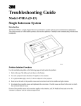
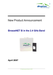
Siting Guidelines
Version 2.2
PN 790-0006-004
TRITON®
SONIC WIND PROFILER
Siting Guidelines
v. 2.2
PN 790-0006-004
Notices
This manual and any examples contained are provided “as is” and are subject to change without notice.
Second Wind Systems Inc. makes no warranty of any kind with regards to this manual, including, but
not limited to, the implied warranties or merchantability and fitness for a particular application. Second
Wind Systems Inc. shall not be liable for any errors or for incidental or consequential damages in
connection with the furnishing, performance, or use of this manual or the examples contained in the
manual.
This document outlines guidelines that should be taken under consideration as a general approach
to siting a Triton. As with any real-world application, environmental and site specific conditions can
vary and cause unpredictable effects on the data. These guidelines cannot account for every possible
scenario, but will provide a methodical strategy to reduce the probability of data degradation due to
these phenomena.
© Copyright 2013 by Second Wind Systems Inc. All rights reserved.
Reproduction, adaptation, or translation of this manual is prohibited without prior written permission
of Second Wind Systems Inc.
Patents. Protected by US Patents:
Patent 7,827,861
Patent 8,004,935
Patent 8,009,513
Other Patents Pending.
About Second Wind
Second Wind develops wind measurement systems that make wind power pay off for consumers, investors
and the environment. The company’s technology provides wind farm developers with the wind data they
need to plan, finance and operate highly efficient wind generation facilities. Second Wind’s systems are
making wind farm development profitable in 50 countries on seven continents. Second Wind’s systems
include Triton, the wind industry’s leading remote sensing system, Nomad® 2 wind data logger systems,
the ProMastTM 60, a 60-meter meteorological mast and the SkyServe® web-based data service. For more
information about Boston-based Second Wind, please visit www.secondwind.com.
Second Wind
15 Riverdale Avenue
Newton, MA 02458
Tel: +1 (617) 467-1500
Fax: +1 (617) 467-1567
E-Mail: [email protected]
[email protected]
Web: www.secondwind.com
PN 790-0006-004
Triton Sonic Wind Profiler Siting Guidelines
3
Table of Contents
1.0 Introduction................................................................................................................................. 5
2.0 Triton Functional Overview........................................................................................................... 6
3.0 Scouting and Accurately Siting a Location ................................................................................... 7
3.1 Mapping Programs................................................................................................................. 7
3.2 Distance................................................................................................................................ 7
3.3 Height................................................................................................................................... 7
3.4 Bearing.................................................................................................................................. 7
4.0 General Guidelines for Siting Tritons............................................................................................ 8
4.1 Terrain Types.......................................................................................................................... 8
4.1.1 Flatland....................................................................................................................... 8
4.1.2 Coastal........................................................................................................................ 8
4.1.3 Complex Terrain........................................................................................................... 9
4.2 Ambient Noise....................................................................................................................... 10
4.2.1 Wildlife Noise............................................................................................................... 11
4.3 Trailer/Platforms/Anchoring..................................................................................................... 11
4.3.1 Additional Ambient Noise............................................................................................. 11
4.3.2 Resonance................................................................................................................... 11
4.4 Prevailing Wind Direction........................................................................................................ 12
4.5 Minimur Setback Distance...................................................................................................... 12
4.6 Fixed Echoes.......................................................................................................................... 13
4.6.1 Siting a Triton by Trees................................................................................................. 14
4.6.2 Siting a Triton Near Buildings....................................................................................... 15
4.6.3 Sample Triton Site........................................................................................................ 16
5.0 Siting Near Met Towers for Correlation Studies............................................................................ 17
6.0 Siting Considerations for Turbine Performance Evaluation............................................................ 18
Appendix 1........................................................................................................................................ 19
List of Figures
Figure 1: The Triton Sonic Wind Profiler.......................................................................................... 5
Figure 2: Triton Beam Configuration............................................................................................... 6
Figure 3a-b: Triton in Beam Transmit (left) and Receive (right) Mode.................................................... 6
Figure 4: Triton Beam Orientation (Top View).................................................................................. 6
Figure 5: Installing a Triton Near the Coastline................................................................................ 8
Figure 6: Installing a Triton on a Plateau........................................................................................ 9
Figure 7: Installing a Triton in Complex Terrain............................................................................... 9
Table 1: Triton Setback Distance as a Ratio of Height.................................................................... 12
Figure 8:
Yawing the Triton to Account for Southerly Wind............................................................... 12
Figure 9: Positioning Fixed Objects Between the Beams.................................................................. 13
Figure 10: Installing a Triton Where Clear-Cutting is Possible with 20m Trees..................................... 14
Figure 11: Installing a Triton Where Clear-Cutting is not Possible with 20m Trees............................... 14
Figure 12: Installing a Triton with Buildings Present........................................................................... 15
Figure 13: Proper Orientation in Relation to Buildings....................................................................... 15
Figure 14: Sample Triton Location.................................................................................................... 16
Table 2: Triton Setback Distance as a Ratio of Height for Correlation Studies.................................. 17
Figure 15: Installing a Triton for Correlation Studies.......................................................................... 17
Figure 16: Installing a Triton for Correlation Studies (Top View)......................................................... 17
Figure 17: Installing a Triton by Turbines........................................................................................... 18
Table 3: Setback Distance............................................................................................................ 19
PN 790-0006-004
Second Wind Systems Inc.
4
1.0
Introduction
Second Wind’s Triton® Sonic Wind Profiler is a SODAR
system designed for wind measurement campaigns in
remote locations. The Triton’s ability to directly profile the
wind resource throughout the rotor swept area of commercial
utility-scale wind turbines makes it a useful stand-alone
measurement device. These siting guidelines outline Second
Wind’s recommended practices for siting a Triton for the
following types of applications:
• Wind resource assessment
• Met tower correlation studies
• Wind condition monitoring on operating wind farms
The first step towards acquiring high-quality and valid Tritondata is to properly site the Triton. Second Wind defines “siting”
as the process of investigating and identifying a suitable
location for the Triton to provide every opportunity available
for it to operate to Second Wind’s performance standards.
Figure 1: The Triton Sonic Wind Profiler
Whether the purpose of the installation is to correlate with
a meteorological (met) tower or to gain knowledge of a site,
certain considerations need to be taken into account during site selection. With this revision, Second Wind is
incorporating the experience gained from hundreds of Triton deployments and nearly 2.5 million operating
hours in a variety of terrains, climates, and applications. Careful attention to siting will help avoid the
surprise of compromised data.
More specific details about Triton installation and operation can be found in the Triton Sonic Wind Profiler
User’s Manual. The Triton Data Processing Guidelines describe best practices for processing data from
Tritons. Both documents are available from Second Wind support.
Second Wind may update these guidelines based on additional field experience, or new capabilities of Triton
and SkyServe. The most recent guidelines are always available from Second Wind support.
For any siting questions or concerns, please contact Second Wind support at:
[email protected] or +1 617-467-1500 ext. 3.
PN 790-0006-004
Triton Sonic Wind Profiler Siting Guidelines
5
2.0
Triton Functional Overview
Understanding how the Triton works is helpful in planning its installation.
The Triton measures wind speed by detecting the Doppler shift of highfrequency acoustic pulses emitted into the atmosphere. The Triton
chirps in three consecutive directions designated as: A-, B- and C-beams
(Fig. 2). All three beam directions are tilted 11.4° from the vertical
axis (Fig. 3a-b) and are spaced 120° from one another (Figure 4). As
described in Section 8.3: Orienting the Triton of the Triton Sonic Wind
Profiler User’s Manual, the A-beam roughly points to the northeast,
the B-beam to the south and the C-beam roughly to the northwest
in the northern hemisphere (In the southern hemisphere, the A-beam
points approximately southwest,
the B-beam faces the north, and
the C-beam is approximately to
the southeast).
Orientation of the Triton is
discussed in more detail in Section
Figure 2:
4.0. After each chirp, some of the
Triton Beam Configuration
acoustic energy is reflected back
(or backscattered) due to thermal
gradients in the atmosphere. The sound that is reflected back is called
the return signal. The Triton measures the return signal and analyzes
the frequency content at specified heights, which we refer to as station
heights. The Triton calculates the wind speed along the beam (the
radial wind speed) from the difference in frequency between the
transmitted signal and the return signal. For every ten-minute interval,
the average radial wind speeds are combined to form the horizontal
wind speed, vertical wind speed and wind direction.
Figure 3a-b:
Triton in Beam Transmit (left)
and Receive (right) Mode
Figure 4: Triton Beam Orientation (Top View)
PN 790-0006-004
Second Wind Systems Inc.
6
3.0
Scouting and Accurately Siting a Location
To properly site a Triton, distances, heights, and bearings must be accurately measured for best performance.
The following tools and techniques should be used before the Triton arrives at the site to ensure that an
appropriate resource assessment location is available.
3.1
Mapping Programs
Online mapping programs that include satellite photography can be useful. Google EarthTM is a free program
offered by Google to access aerial photography of nearly every location on the planet. It is not intended to
be a high-grade surveying or cartographic program, but it is excellent for providing an initial assessment of
a particular location. Various measuring tools incorporated in the program can help in finding a suitable
position for the Triton. Aerial photos should always be accompanied by a site visit, as Google’s aerial photos
can be outdated and site conditions can change. For more information please visit http://earth.google.com.
3.2
Distance
On-site, horizontal distance to a fixed object should be measured with a quality infrared or laser rangefinder.
The NikonTM Forestry Pro or an equivalent model is ideal (specifications are on-line at www.nikon.com).
Standing from the potential position of the Triton, all fixed objects within a 200m radius should be noted
and recorded on the Triton Site Information Form and Checklist (Refer to Section 8.1 of the Triton Sonic
Wind Profiler User’s Manual).
3.3
Height
An infrared or laser rangefinder is capable of measuring the height of objects. Any significantly tall object
(>5m) can reflect stray signals from a Triton and reduce data quality. Please refer to Section 4.6 Fixed
Echoes.
3.4
Bearing
It is important to have accurate compass bearing readings when siting a location for several reasons:
• Wind Direction
The default Triton azimuth assumes that the array door is facing true north and the solar
panels are facing true south and will report all wind direction measurements using this default
configuration. On-site personnel should either orient the Triton according to this configuration
OR should enter any azimuth offset in the Triton ProLinkTM to compensate for the discrepancy
(Refer to Section 8.6.6.1 of the Triton Sonic Wind Profiler User’s Manual).
NOTE: The azimuth offset must be manually set in the southern hemisphere, as the Triton’s orientation
needs to be reversed.
• Avoiding Echoes from Objects
If the Triton must be sited close to fixed objects, the Triton should be rotated to point the
beams away from the object. Refer to Section 4.6 Fixed Echoes for more information.
• Solar Charging
To maximize the charging ability of the solar panels, they must directly face the equator or as
close to it as possible to allow for maximum exposure to sunlight.
PN 790-0006-004
Triton Sonic Wind Profiler Siting Guidelines
7
4.0
General Guidelines for Siting Tritons
Whatever application the Triton will be used for, there are several main siting issues that need to be considered:
1.
2.
3.
4.
5.
4.1
Terrain types
Ambient noise
Trailers/Platforms/Anchoring
Prevailing Wind Direction
Surrounding fixed obstacles
Terrain Types
The versatility of the Triton enables it to be deployed across a broad range of terrain types. Just as wind
conditions can depend on the topography and climate of a location, so can the Triton’s performance. The
following section details recommendations for siting a Triton in common types of terrain.
4.1.1
Flatland
Flatland typically includes agricultural farmland, open prairie or desert. It has negligible fluctuation in
elevation over a large area (>5 km2).
• Tritons placed in open terrain can experience high wind speeds at ground level that can cause
significant noise, reducing data availability at higher heights. Shielding at ground level can reduce
noise and increase data recovery.
4.1.2
Coastal
Tritons can be deployed in coastal or other marine
environments. Any offshore applications, though,
should be discussed with Second Wind support
at:
+1 617-467-1500 ext. 3 or
[email protected].
Figure 5: Installing a Triton Near the Coastline
• Any Triton placed near a marine environment should be placed on a stable platform that does not
rock.
• The Triton should be raised above, or placed away from, any possible waves.
PN 790-0006-004
Second Wind Systems Inc.
8
4.1.3 Complex Terrain
The features of complex terrain affect wind speeds, directions, and turbulence. Ridgelines, cliffs, plateaus and
other extreme locations can cause a non-uniform wind flow curvature. The Triton’s wind speed computations
assume that the wind flow angle through the measurement area is constant. In complex terrain, it is possible
that this assumption no longer holds true. Second Wind has used computation fluid dynamics (CFD) flow
modeling to calculate and apply adjustments to the Triton’s readings with good success. If you are interested
in learning more, contact Second Wind support at [email protected] or +1 617-467-1500 ext. 3.
1. Near a cliff edge, the winds will have a
strong vertical component. A Triton on
the edge of a cliff (within 5m) will most
likely record large amounts of vertical
wind velocity depending on wind direction
(Figure 6). To accurately measure the
horizontal wind speeds on site, place the
Triton more than 5m from the edge of
the cliff.
2. For complex wind geometry, increasing the number of measurement sites
will reduce uncertainty and provide
a better understanding of the wind
resource at a particular location.
Figure 6: Installing a Triton on a Plateau
3. The ground level wind speeds on
ridgelines can be extremely high, creating
ambient noise which will lead to reduced
data availability at higher heights.
When possible, situate the Triton on the
downwind (leeward) side of a ridgeline,
where the hill will offer some shielding
from the wind (see Figure 7).
Figure 7: Installing a Triton in Complex Terrain
PN 790-0006-004
Triton Sonic Wind Profiler Siting Guidelines
9
4.2
Ambient Noise
Because the Triton relies on acoustic reflections from the atmosphere, too much noise at a site can affect
the quality of data. Ambient noise will be a problem if it is:
• Loud
• Sustained
• Similar in frequency to the Triton
Every time a Triton chirps, the return signal is always its strongest immediately after it reflects off temperature
fluctuations at the lower heights. As the signal climbs and travels through more of the atmosphere, it
progressively weakens as more of the signal deflects away from the Triton. Therefore, at locations with more
ambient noise, the Triton is less likely to recover data at the upper station heights since there will be more
interference with the weaker return signal.
The Triton computes a Quality Factor that rates the quality of the data for each 10-minute period. By
comparing the strength of the return signal at each station height to the ambient noise levels at the site, the
Triton calculates a Signal-to-Noise Ratio (SNR) and uses this in computing the Quality Factor. A significantly
loud and constant ambient noise source within the Triton’s operating frequency can affect the return signal
at the upper station heights, resulting in a significantly lower SNR and Quality Factor.
Ambient noise sources commonly found at most wind measurement sites, such as roads, railroads, and
generators, can cause issues with data recovery under certain circumstances. Any constant and loud noise
source can reduce data returns at the upper station heights. If the noise is infrequent (such as a rarely used
road) or if the Triton is located sufficiently far from the source, then the average recovery rates should not
suffer.
Ground-level wind speeds greater than 20 m/s can cause a significant amount of wind noise at an exposed
location. Some degradation of quality at the higher station heights should be expected unless the Triton is
sheltered from the wind. The Triton can be sheltered by topographic features, or by trees around the Triton.
If the Triton is sited in a location where high external ambient noise is known to exist, consideration should
be given to introducing a barrier to the noise source. The use of hay bales surrounding the Triton, or a
container that encloses the Triton (opened at the top) have resulted in higher data quality, and higher data
recovery in high ambient noise locations. Second Wind support can advise on specific sheltering concerns.
On a site with more than one Triton, take care to plan the distance between the Tritons. If two Tritons are too
close to each other, they will interfere with each other’s measurements. We recommend a minimum spacing
between Tritons of 600 meters. This is true for the Triton and other SODAR systems as well. PN 790-0006-004
Second Wind Systems Inc.
10
4.2.1
Wildlife Noise
Some insects and amphibians, such as crickets and frogs, emit a noise with similar frequency components to
the Triton (~4500 Hz ±250 Hz, dependent on temperature) that can reduce data quality. However, Triton
Sodar firmware versions 2.0 and higher have the ability to automatically filter out these noises and improve
data quality. By default, a Triton with these firmware versions includes:
• A background noise filter that mitigates the adverse effects of insect and wildlife noise.
• An enhanced Quality Factor (Q Factor) algorithm that reduces erroneous scatter in the Triton
data.
The net effect is a more intelligent Sodar application that minimizes the need for additional “cleaning” of
Triton data after it is exported from SkyServe.
4.3
Trailer/Platforms/Anchoring
The Triton adapts well to alternative installation strategies such as trailers and snow platforms. Trailers
facilitate quick and easy redeployment of Tritons. Where snow accumulation is significant, snow platforms
have been built to keep the Triton above the snow. At locations with high ground-level wind speeds, such as
ridgelines, outriggers and sandbags have been used in addition to earth anchors to secure the Triton. For
any customized platform or anchoring scheme, the following two issues should be addressed:
4.3.1
Additional Ambient Noise
Some additional sources of ambient noise can include:
• Wind passing throughout the platform or anchoring system can introduce a high level of ambient
noise, and data recovery rates at higher station heights may suffer. If earth anchors cannot be used
at the site, we recommend mounting the Triton on a pair of outriggers to offer additional stability.
• Do not use nylon webbing straps. These can vibrate in high winds, causing significant ambient noise that
can degrade data quality.
•
• Another common mistake is to leave securing devices hanging loose (i.e. chains, ends of rope or straps,
etc.) that can flap in the wind or hit the side of the Triton. It is essential to secure or tie down any loose
ends so that additional ambient noise will be minimized.
Please refer to the Triton Anchoring Guidelines in the Triton Sonic Wind Profiler User’s Manual (Sec. 8.7)
for further information.
4.3.2
Resonance
If there are metal components on the platform or trailer, the Triton’s chirp may cause the metal parts to
ring (i.e. resonate). The resonance can pollute the return signal and introduce noise to the wind speed
measurement. Do not place a Triton directly on a metal surface; instead, have some acoustic dampening
material, such as plywood, between the metal and the Triton. Ideally, there should be no direct contact
between the Triton and an un-dampened metal part. Be careful when bolting a Triton to the metal deck
of a platform. The metal coupling between the bolts and the metal can resonate. If possible, use a rubber
stopper or gasket on the bolting hardware to reduce vibration. All platform and trailer designs should be
discussed with Second Wind prior to deployment.
For anchoring methods and instructions, refer to the Triton Sonic Wind Profiler User’s Manual.
PN 790-0006-004
Triton Sonic Wind Profiler Siting Guidelines
11
4.4
Prevailing Wind Direction
The B-beam typically faces south in the northern hemisphere
and north in the southern hemisphere to maximize solar charging
effectively. Figure 16 shows the location of the three Triton beams.
However, in a small number of cases, measurement bias has been
observed in high winds when the wind is oriented in a narrow sector
(+/-15˚), coincident with the B-beam orientation. In the northern
hemisphere, this phenomenon could occur when the wind is from
the south and in the southern hemisphere, when the winds are from
the north.
In these cases, to avoid the possibility of this high wind bias, Second
Wind recommends yawing (rotating the Triton about its vertical axis)
to a new position that locates the B-beam of the Triton at least 30˚
away from the prevailing wind direction (Figure 8).
Figure 8: Yawing the Triton
to Account for Southerly Wind
4.5
If the wind orientation merits yawing of the unit, the efficiency of the
solar panels may be reduced, particularly when the Triton is located
at higher, or lower, latitudes. Second Wind can estimate the impact
of yawing on available energy.
Minimum Setback Distance
The Triton needs to be located in a
position such that none of the three
beams are blocked by any objects on
the site. Therefore, the Triton must be
setback a minimum distance from any of
these objects such that all three beams
have a clear path above.
Table 1 shows the obstacles typically
encountered when siting a Triton and
the minimum setback distance the
Triton must be placed from them. For
instance, for every meter of height of a
treeline, the Triton must be half a meter
away from the longest branches of
that treeline. Always measure from the
Table 1: Triton Setback Distance as a Ratio of Height
branches, as measuring from the trunk
of the tree may result in the Triton being
too close to the tree. For buildings, the Triton must be three times the height of the building away. For other
considerations when siting near these objects, please refer to the appropriate sub-sections below in Section
4.6 Fixed Echoes. For minimum setback distances when performing a met tower correlation study, please
refer to Section 5.0 Siting Near Met Towers for Correlation Studies.
PN 790-0006-004
Second Wind Systems Inc.
12
4.6
Fixed Echoes
Fixed objects are objects like trees, buildings, or met towers. If the Triton is placed too close to a fixed object,
sound reflections from the object may interfere with one of the main beams and adversely impact data
collection at all station heights. These sound reflections are called “fixed echoes.” The Triton’s three beams
are each oriented 11.4° from vertical and 120° apart horizontally. The design of the Triton enclosure and
speaker array ensures that the majority of the acoustic energy is transmitted along these main beam paths.
Aside from the acoustic energy from the main beams, there is a small amount of “side lobe” energy that
travels laterally from the unit. If stationary objects are in the path of the side lobes (or the main beams),
echoes with a zero frequency shift may be returned to the Triton.
In such circumstances, the Triton’s returned signal would be a blend of fixed echoes and reflections from the
atmosphere exhibited at a station height roughly equal to the Triton’s distance from the fixed obstacle. The
fixed echoes and the actual wind speeds will be averaged together to create a wind speed that is low. This
is known as a low bias. For example, a fixed object that is 60m laterally from the Triton could cause a low
bias in the Triton’s 60m wind measurement.
Second Wind has developed a fixed echo rejection algorithm for the Triton that significantly reduces the
effects of fixed echoes. However, in low wind situations it is difficult for the algorithm to differentiate between
wind measurements and echo sources, so Second Wind recommends avoiding sources of echoes whenever
possible while siting the Triton.
In real-world situations it is not always possible to avoid all sources of
echoes. Therefore, one should consider the beam orientation with respect
to surrounding obstacles (see Figure 9). The Triton should be situated
such that none of the acoustic beams are aimed directly at a fixed object.
This will reduce the strength of the fixed echoes, which will maximize the
effectiveness of the echo rejection algorithm and minimize any low wind
bias in the measured wind data.
If fixed echoes cannot be addressed via rotation or translation due to the
geometry of the site, the Triton can be oriented to anticipate the low wind
bias depending on the purpose of the study. For example, the Triton can
be placed 30m-40m from a fixed obstacle causing the low bias to appear
at a lower station height that is of less significance to the measurement
campaign. The effects on solar energy capture should be taken into
account when orienting the Triton away from the true North-South axis.
Figure 9: Positioning Fixed
Objects Between the Beams
If an object causes a fixed echo that overwhelms the signal, a new location may be required. Second Wind
support can run a Triton Performance Study to scrutinize the first 10 days after an installation or relocation.
The study will determine if there are any significant sources of fixed echoes that may be affecting the data
as well as other performance parameters. If you are interested in receiving a study, please contact Second
Wind support at [email protected] or +1 467-1500 ext. 3.
PN 790-0006-004
Triton Sonic Wind Profiler Siting Guidelines
13
4.6.1
Siting a Triton by Trees
Trees can pose challenges for the Triton at a potential wind site, but can be beneficial as well. Siting the
Triton the proper distance away and with proper orientation is critical to avoid fixed echoes. The type of
trees, density, and foliage can all affect the relative strength of the echoes. However, terrain with taller and
denser foliage will have higher surface roughness and can shield Tritons from high ground level wind speeds
and their ambient noise.
Due to the indistinct geometry of forests and treelines, resultant echoes may not affect the data at the exact
distance of the first line of trees. The echo may be exhibited up to 15 m beyond the beginning of the treeline
depending on the density of the forest behind it. For example, a treeline that is 30m from the Triton can
affect the 40m or, possibly, 50m data.
When tree clearing is possible, remove all trees within a radius of the Triton equal to half of the height of
the trees (Table 1). This relatively short distance will cause fixed echoes from the trees to affect the lower
station heights where little or no energy will be generated. The 40m data may exhibit a low bias, however
measurements above that height will not be affected.
Some considerations for clear-cutting should be
made if the Triton relies on solar charging and if
the on-site solar resource may be limited. Figure 10
depicts an example site with 20m trees surrounding
a 40m diameter clear-cut opening in the forest.
The Triton is 10m from the northern edge of the
clearing to satisfy the setback outlined in Table 1
and 30m from the southern edge to allow sufficient
sunlight for the solar panels. Please refer to
Appendix 1 for more information on clear-cutting
for solar charging.
Figure 10: Installing a Triton
Where Clear-Cutting is Possible with 20m Trees
If clear-cutting is not possible, please use the following
guidelines:
1. Orient the Triton so none of the beams are
pointed perpendicularly to the treeline. Note and
record the Triton’s azimuth. Be aware that solar
charging can be less efficient if the solar panels
are not at a true 180° (northern hemisphere) or
0° (southern hemisphere) azimuth.
2. The Triton should be a minimum distance away
from any tree or treeline equal to half of the height
of the trees to avoid anything from blocking the
main path of any of the beams.
PN 790-0006-004
Figure 11: Installing a Triton
Where Clear-Cutting is not Possible with 20m Trees
Second Wind Systems Inc.
14
3. If the Triton is solar-powered, and there is low solar insolation at the site, then it should be located
with the minimum setback against the treeline with the most sun exposure to prevent shading of the
solar panels.
4. If the predominant wind direction is known before siting, place the Triton with the minimum setback
against the windward side of the clearing (Figure 11).
4.6.2
Siting a Triton
Near Buildings
Buildings, when present, can affect
the Triton data if siting issues are not
properly addressed. Buildings can
provide very strong fixed echoes due
to their broader dimensions and reflective geometry. Please adhere to
the following guidelines when siting
near buildings:
Figure 12: Installing a Triton with Buildings Present
1. The minimum distance between the Triton and any building should be equal to 3 times the height
of the building.
2. The Triton should be positioned so that the building is outside the path of any of the three beams. The
red area in Figure 12 indicates the minimum 45m distance that the Triton should be located away from
that particular building. The Triton, located 60m from the building, is well outside the exclusion zone.
3. The Triton should be located so that no side of the building is directly facing the Triton. In other words,
no side of the building should be perpendicular to any line coming from the Triton. This way, sound
waves will be reflected away from the Triton instead of directly back at it.
Figure 13 shows four positioning scenarios:
• Of the four, only position 1 is a suitable
location for the Triton in relation to the
building. The building is 15m tall; therefore
the Triton should be at least 45m away.
Additionally, the Triton is positioned so
that the building lies between the A- and
B-beams.
• Position 2 is a poor location as the building
is at a 180° azimuth and directly in the path
of the B-beam. Also, the path of the beam
is perpendicular to the face of the building.
• Position 3 is within the 45m setback from
the building and is subsequently a poor
position.
Figure 13: Proper Orientation in Relation to Buildings
• Position 4 has the A-beam of the Triton
projected directly at the building, thus making it a poor site. Additionally, concave corners of buildings
are more prone to reflecting sounds waves and should be avoided.
PN 790-0006-004
Triton Sonic Wind Profiler Siting Guidelines
15
4.6.3
Sample Triton Site
This section illustrates how to incorporate the different guidelines in an applied setting. Figure 14 depicts a
Triton being used in a project where a correlation study is not being performed.
This site is a typical flatland agricultural site. The Triton is placed in an optimal position in relation to several
immobile objects that could create fixed echoes.
• The 60m met tower (1) is at least 60m from the Triton and is also due west so it is not in the
path of any of the Triton’s beams.
• The forest to the north of the Triton (2) is at least the minimum setback from the Triton and also
lies between the Triton’s A- and C-beams.
• The barn (3) at 140m from the Triton is positioned between the A- and B-beams, but more
importantly, none of the faces of the barn are directly facing the Triton.
• The cabin (4) is not of any importance to the Triton as it is outside its 200m-measurement
radius.
Figure 14: Sample Triton Location
PN 790-0006-004
Second Wind Systems Inc.
16
5.0
Siting Near Met Towers for Correlation Studies
Some customers may wish to correlate
their Triton with an on-site met tower
before it is relocated for independent
measurement. However, it is important
to note that the Triton does not
require calibration for it to be able to
undertake a measurement campaign.
This section details additional siting
considerations for met tower correlation
studies that may not be required
for standard resource assessment.
Table 2 details the minimum setback
distances that must be used when
for Correlation Studies
siting a Triton near a met tower for a
correlation study. It is critical that the
Triton is sufficiently far from the tower in order to allow for it to properly correlate with all anemometers at
each station height.
Table 2: Triton Setback Distance as a Ratio of Height
To optimize the correlation, siting decisions will place a priority on high quality data at the correlation
heights. These guidelines apply to both tubular and lattice towers.
1. The elevation of the Triton should be within 5m of the base elevation of the tower.
2. The Triton should be no farther than 150m from the base of the tower.
3. There should be no obstacles that could cause a fixed echo within a radius of the Triton equal to the
height of the tower plus 10m. (For example, if using a 60m tower, there should be no fixed echoes
within a 70m radius of the Triton such as Figures 15 and 16.)
4. The Triton should not be placed in a position where the tower is in the direct path of any of the
Triton’s three beams.
Figure 15: Installing a Triton for Correlation Studies
PN 790-0006-004
Figure 16: Installing a Triton
for Correlation Studies (Top View)
Triton Sonic Wind Profiler Siting Guidelines
17
6.0
Siting Considerations for
Turbine Performance Evaluation
The Triton can be used on operating wind farms to measure wind conditions for many applications including
performance testing and forecasting. The portability of the Triton allows for flexibility in strategically
measuring shear, veer, turbulence and wake effects at multiple sites on a wind farm. To ensure high quality
data when installing a Triton next to a turbine, the guidelines below should be followed.
1. If conducting a wake study, the minimum distance between the Triton and turbine should be
approximately 2 times the hub height (Figure 17).
2. None of the Triton’s beams should be directly pointed at the turbine.
3. If conducting a correlation study with a met tower, ensure that there is at least a distance equal to
the total height of the turbine (hub height plus blade length) between the Triton and the turbine.
Figure 17: Installing a Triton by Turbines
PN 790-0006-004
Second Wind Systems Inc.
18
Appendix 1
Clear-Cutting for Solar Charging
As outlined in Section 4.6.1, some considerations may have to be made for clear-cutting a location to allow
for solar charging. Several variables need to be taken under review as increasing the distance to the treeline
on the sunward side of the Triton can also increase the likelihood of creating a fixed echo at an undesirable
station height.
Determining the distance from the sunward treeline is largely dependent on two things: the height of the
trees and the elevation of the sun. To measure the height of the trees, please refer to Section 3.3. The
elevation of the sun relies upon the date and the location of the Triton.
The National Oceanic and Atmospheric Administration has an online solar calculator that can provide the
solar elevation for any date and location. The calculator is located at:
http://www.esrl.noaa.gov/gmd/grad/solcalc/
The solar elevation should be calculated over a series of dates at noon in the winter months since that is
when the sun will follow its lowest path through the sky. Using the following formula, the setback distance
can be graphed over this period to determine a suitable setback distance:
d=
h
Ta n (θ )
Where d is the setback distance from the sunward treeline, h is the height of the treeline, and θ is the solar
elevation. An example of such a graph is displayed in Table 3 with a Triton at a 40˚ latitude.
At this point, the setback distance should be determined with precedence given to either solar charging or
echo management if the distance cannot satisfy both priorities.
Table 3: Setback Distance
PN 790-0006-004
Triton Sonic Wind Profiler Siting Guidelines
19