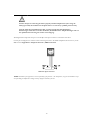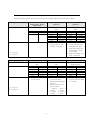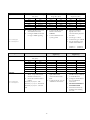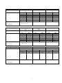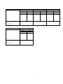
1
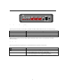
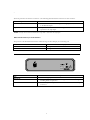
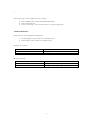
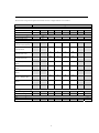
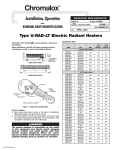
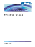
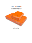
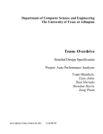
SLA Operation Manual
COPYRIGHT
This manual and the accompanying product are copyrighted by Interalia with all rights reserved.
Copyright © 2008 Interalia Inc.
4110 – 79th Street NW
Calgary, Alberta, Canada
T3B 5C3
(403) 288-2706 (phone)
(403) 288-5935 (fax)
www.interalia.com
TRADEMARKS
Interalia ® is a registered trademark of Interalia Inc.
Table of Contents
INTRODUCTION --------------------------------------------------------------------------------------------------------------------------------- 1
FRONT VIEW ------------------------------------------------------------------------------------------------------------------------------------ 2
LIGHT EMITTING DIODES (LEDS) -------------------------------------------------------------------------------------------------------- 2
RED PUSH BUTTONS ----------------------------------------------------------------------------------------------------------------------- 2
INTERFACE CONNECTORS ----------------------------------------------------------------------------------------------------------------- 3
MSG SLIDE SWITCH, TWO POSITION --------------------------------------------------------------------------------------------------- 3
REAR VIEW ------------------------------------------------------------------------------------------------------------------------------------- 3
INSTALLATION AND OPERATION ------------------------------------------------------------------------------------------------------------- 4
INSTALLATION ------------------------------------------------------------------------------------------------------------------------------- 4
RECORD A MESSAGE ---------------------------------------------------------------------------------------------------------------------- 4
PLAY A MESSAGE --------------------------------------------------------------------------------------------------------------------------- 5
LINKING MESSAGES ------------------------------------------------------------------------------------------------------------------------ 5
OPTION SWITCH ------------------------------------------------------------------------------------------------------------------------------- 6
OPERATION MODES --------------------------------------------------------------------------------------------------------------------------- 7
TROUBLESHOOTING --------------------------------------------------------------------------------------------------------------------------- 9
APPENDIX A – RJ-11 LINE CONNECTOR PIN-OUT ------------------------------------------------------------------------------------- 10
APPENDIX B – TELEPHONE NETWORK / PBX CONNECTIONS ------------------------------------------------------------------------ 11
APPENDIX C – NOTES FOR UK SYSTEMS ----------------------------------------------------------------------------------------------- 16
APPENDIX D – TECHNICAL SUPPORT AND REPAIRS ----------------------------------------------------------------------------------- 17
APPENDIX E – APPROVALS ---------------------------------------------------------------------------------------------------------------- 18
APPENDIX F – TECHNICAL SPECIFICATIONS -------------------------------------------------------------------------------------------- 21
LIMITED WARRANTY ------------------------------------------------------------------------------------------------------------------------ 22
i
INTRODUCTION
The Single Line Announcer (SLA) is a solid-state, digital announcer designed for continuous maintenance-free
operation. The SLA provides high quality recorded messages for telephone applications including ACD / UCD,
DID intercept, after hours, hotel wake up and general public information announcements.
Up to 2 messages can be recorded on the SLA allowing the user to pre-record day and night / holiday messages. A
simple change to the 2 positions slide switch from MSG 1 to MSG 2 allows complete control over what your caller
hears.
The SLA allows the user to link both messages together (e.g., the same message in two languages).
The SLA uses non-volatile FLASH based memory that will retain the recorded messages during power
interruptions. The SLA is equipped with 1 minute of recording time. The messages can be recorded from a
handset or downloaded from a tape deck.
Installation and operation are simple and the SLA interfaces with all major telephone systems.
1
FRONT VIEW
LIGHT EMITTING DIODES (LEDS)
The front panel of the SLA has four LEDs. The MSG 1 & MSG 2 LEDs indicate the status of recorded messages:
When the MSG LED is…
Off
On
Blinking
•
•
•
The message is…
Not Recorded
Recorded
Selected and ready to be recorded or played back using the handset.
While a message is being recorded, the REC LED is illuminated. While a caller is on the phone line, the LINE
LED is illuminated.
RED PUSH BUTTONS
The front panel has three red push buttons. This table describes the function of each button.
Button Name
MSG
REC
PLAY
•
•
•
•
•
Function
Press the MSG button to toggle between MSG 1 and MSG 2
Press the REC button twice to begin recording a message
Press the REC button once to stop / end recording
Press the PLAY button once to begin message playback
Press the PLAY button a second time to stop / end message playback
2
INTERFACE CONNECTORS
The front panel has two interface connectors. The following table describes the function of each connector.
Input Connector
Handset
•
Tape
•
Function
The SLA handset (used for message recording / playback) is connected
to the Handset Input.
A tape deck can be used to record messages to the SLA. Connect the
tape deck to the Tape Input.
NOTE: The tape deck overrides the Handset when a tape deck is connected to the Tape Input.
MSG SLIDE SWITCH, TWO POSITION
The position of the Slide Switch determines which message the SLA will play to an incoming call.
When the MSG Slide Switch is in…
Position 1
Position 2
The SLA plays…
Message 1
Message 2
REAR VIEW
Connectors & Switches
Line
Option Sw
•
•
Pwr In
•
Description
The incoming telephone line is connected to the Phone Line jack.
The 8-pin Option Switch is used to configure different SLA settings
including Mode of Operation.
Connect the power adapter that came with the SLA to the Power Input
Connector.
3
INSTALLATION AND OPERATION
INSTALLATION
Caution: Except for connecting the SLA to properly installed telephone line jacks using the
cable(s) provided, the installation of telephone lines is to be done by qualified personnel only.
Vorsicht: Außer dem Anschließen des SLA an richtig angebrachte Telephonleitung
Steckfassungen stellte das Verwenden der Kabel, die Installation der Telephonleitungen soll von
nur qualifiziertem Personal getan werden zur Verfügung.
Follow these steps to install the SLA:
1)
2)
3)
4)
Connect the incoming telephone line to the RJ-11 Line connector.
Configure the 8-position option switch using the Option Switch table.
Connect power to the SLA using the adapter supplied by Interalia.
Connect the handset or tape deck to the Handset / Tape input.
NOTE: The tape deck overrides the Handset when a tape deck is connected to the Tape Input..
RECORD A MESSAGE
Follow these steps to select and record a message:
1)
2)
3)
4)
5)
Press the MSG button until the desired MSG LED blinks.
Press the REC button twice.
Record your message into the handset or press “play” on the tape deck if using the Tape input to
record.
Press the REC button to stop / end recording.
Play the message to verify content and voice clarity.
NOTE: The tape deck overrides the Handset when a tape deck is connected to the Tape Input.
4
PLAY A MESSAGE
Follow these steps to select and play (listen to) a message:
1)
2)
3)
Press the MSG button until the desired MSG LED blinks.
Press the PLAY button.
Listen to the message. Press the PLAY button to stop message play back.
LINKING MESSAGES
The SLA has two message playback configurations:
•
•
Not linked (Option switch / Pin #7 in the OFF position)
Linked (Option switch / Pin #7 in the ON position)
Messages are not linked:
When the MSG Slide Switch is in…
Position 1
Position 2
The SLA plays…
Message 1
Message 2
Messages are linked:
When the MSG Slide Switch is in…
Position 1
Position 2
The SLA plays…
Message 1 followed by Message 2
Message 2 followed by Message 1
5
OPTION SWITCH
The SLA has an 8-position Option Switch that must be configured before it is installed.
Function
Pin Setting
1
3
4
5
6
OFF
ON
ON
ON
Ring Start without Loop
Current Check
ON
OFF
ON
ON
Continuous Play with
Control Pulse relay
ON
ON
ON
OFF
Continuous Play without
Control Pulse relay
OFF
ON
ON
OFF
Pulse Start / Level
Return
ON
OFF
OFF
ON
Pulse Start / Pulse
Return
OFF
OFF
OFF
ON
Level Start / Pulse
Return
OFF
OFF
ON
ON
Level Start / Pulse
Return - Multiple Play
ON
ON
OFF
ON
Level Start / Level
Return
OFF
ON
OFF
ON
Offline
ON
ON
ON
ON
Volume Control
ON
Maximum Level
OFF
Minimum Level
CP Contact during message play
CP Normally Closed
CP Normally Open
Operation Mode
Ring Start with Loop
Current Check (Default)
2
7
8
ON
OFF
Message to Line Configuration
Linked Messages
Un-linked Messages
Number of Rings Before Answer
One
Three
ON
OFF
ON
OFF
6
OPERATION MODES
The SLA can interface with a CO line, Key System, or Private Branch Exchange (PBX). This section describes the
different line operation modes supported by the SLA. Pins 3, 4, 5, and 6 on the 8 position Option Switch are used
to configure the operation mode.
NOTE: CP = Control Pulse.
•
Ring Start Loop Current Check
The message plays once in response to a Loop or Ground Start signal. The message will stop playing before
completion if the loop current is removed from the line. The line disconnects when the message is finished.
•
Ring Start without Loop Current Check
The message plays once in response to a Loop or Ground Start signal. The message will not stop playing if
loop current is removed from the line. The line disconnects when the message is finished.
•
Continuous Play with Control Pulse relay
The message plays continuously to the line. The CP contacts inside the SLA toggle position for approximately
250 mSec. at the start of the message.
•
Continuous Play without Control Pulse relay
The message plays continuously to the line. The CP contacts inside the SLA do not toggle their position at
the start of the message.
•
Pulse Start / Level Return
The message plays once in response to a start signal. The CP contacts inside the SLA toggle position while
the message is playing.
•
Pulse Start / Pulse Return
The message plays once in response to a start signal. The CP contacts toggle position for approximately 250
mSec. at the end of the message.
7
•
Level Start / Pulse Return
The message plays once in response to a start signal. The CP contacts inside the SLA toggle position for
approximately 250 mSec. at the start and end of the message. The message stops playing if the start signal is
removed.
•
Level Start / Pulse Return - Multiple Play
The message plays in response to a start signal. The CP contacts inside the SLA toggle position for
approximately 250 mSec. at the start and end of the message. The message stops playing if the start signal is
removed. The message plays repeatedly until the start signal is removed.
•
Level Start / Level Return - Play Once
The message plays once in response to a start signal. The CP contacts inside the SLA toggle position while
the message is playing. The message stops playing if the Start signal is removed.
8
TROUBLESHOOTING
If the SLA is not working properly, please review the following troubleshooting steps. If the problem persists, see
Appendix D – Technical Support and Repairs.
Problem
SLA does not power
up
SLA does not answer
calls
Poor recording
quality from the
handset
Partial message
recorded
Unable to record
from the Handset?
Message playback
volume is too high or
too low
•
•
•
Verify the following…
Is the power adapter connected between the SLA and the power outlet?
•
•
•
•
Is the message recorded?
Is the Option Switch set correctly? See Operation Mode Selection and Option Switch
Settings.
Is the MSG slide switch set correctly?
Is the telephone line / port working?
Is the handset the Interalia handset that came with the SLA?
Speak directly into the handset while recording.
•
Is the message(s) longer than the total recording time (minutes) of the SLA?
•
•
•
Is the handset the Interalia handset that came with the SLA?
Verify that a tape deck is not connected to the Tape jack.
Is pin 1 of the option switch in the correct position? Refer to the Option Switch chart for
the correct setting.
9
APPENDIX A – RJ-11 LINE CONNECTOR PIN-OUT
Caution: Except for connecting the SLA to properly installed telephone line jacks using the
cable(s) provided, the installation of telephone lines is to be done by qualified personnel only.
Vorsicht: Außer dem Anschließen des SLA an richtig angebrachte Telephonleitung
Steckfassungen stellte das Verwenden der Kabel, die Installation der Telephonleitungen soll von
nur qualifiziertem Personal getan werden zur Verfügung.
The diagram below represents the pin-out of the RJ-11 line input connector on the back of the SLA.
Use this pin-out diagram as a reference when connecting the SLA to the Public Telephone Network or any of the
PBXs listed in Appendix B – Telephone Network / PBX Connections
SLA Line input connector
NOTE: Installation of the equipment is the sole responsibility of the purchaser. The manufacturer, its agents and distributors accept
no responsibility for malfunction or damage caused by improper connection of the unit.
10
APPENDIX B – TELEPHONE NETWORK / PBX CONNECTIONS
The following tables represent how the SLA connects to most Public Telephone Networks and / or PBXs.
Switch Type
Public Network, PBX
Analog Station, Analog
Centrex Line
Ring Start
Operation Mode
SLA
Ring
Tip
PBX
Ring
Tip
Lucent G2, G3, Definity
(option 1)
Lucent G2, G3, Definity
(option 2)
Pulse Start / Level Return
(NO)
Level Start / Pulse Return
(NO)
SLA
Ring
Tip
Start Start +
CP 1
CP 2
NOTES:
•
•
PBX
Ring
Tip
Battery *
S
AL1
Ground
Use a SN231 card
The ground must come
from the circuit pack
NO = Normally Open
NC = Normally Closed
SLA
Ring
Tip
Start Start +
CP 1
CP 2
•
•
•
•
PBX
Ring
Tip
Battery *
SZ1
S
S1
Use a TN 763C Card
The ground must come
from the Circuit pack
Strap the SZ lead to the
ground of the external
power supply
Strap the –48VDC to the
Start – on the SLA.
NOTE: * = Identifies the signal from the PBX power supply or the System Ground.
Switch Type
Operation Mode
AT&T System 75 / 85
Pulse Start / Level Return
(NC)
SLA
Ring
Tip
Start Start +
CP 1
CP 2
NOTES:
•
AT&T Dimension 2000
Pulse Start / Level Return
(NC)
PBX
Ring
Tip
Battery *
S
AL1
Ground
SLA
Ring
Tip
Start Start +
CP 1
CP 2
•
Ground must come from
the circuit pack
•
NO = Normally Open
NC = Normally Closed
11
Ericsson MD 110
Pulse Start / Level Return –
Single Play (NO)
PBX
Ring
Tip
Battery *
S2
AL1
Battery *
Connect the SLA to the
LC13 Circuit Pack ,
Recorded Announcement
Interface
Set the switches on the
LC13 as follows:
Circuit 0
Circuit 1
4 – Open
1 – Open
5 – Closed
2 – Closed
6 – Open
3 - Open
SLA
Ring
Tip
Start Start +
CP 1
CP 2
•
•
PBX
T-Rec
R-Tx
M
Aux GND
S – GND
E
Var. = 00, Type = RA1
Connect S Bat from PBX
to Aux. Bat.
Switch Type
Operation Mode
Harris 20 / 20 LH & M
Level Start / Pulse Return – Single
Play (NO)
SLA
Ring
Tip
Start Start +
CP 1
CP 2
NOTES:
•
•
Hitachi EDX / MDX / LDX
Level Start / Pulse Return –
Single Play (NO)
PBX
Ring
Tip
M
Ground *
E
Ground *
Connect the SLA to a 2 or 4
wire E&M Trunk Card
Configure E&M Trunk Card
for Type 1 E&M signaling
SLA
Ring
Tip
Start Start +
•
•
Hitachi HCX – 5000
Level Start / Pulse Return –
Single Play (NO)
PBX
Ring
Tip
Battery *
SSL0
Connect the SLA to the
Hitachi card number
4SRBWT
Connect SS0 lead to the
system ground
NO = Normally Open
NC = Normally Closed
SLA
Ring
Tip
Start Start +
CP 1
CP 2
•
•
•
•
HCX programming:
Specify one or two
announcements played to
the caller
Trunk type = OGT
Connection type =TKTH
Set the strapping on the
4ANIF card as follows:
TM00 1-2
TM01 1-2
Switch Type
Operation Mode
NEC NEAX 2400
Level Start / Pulse Return – Single
Play (NO)
SLA
Ring
Tip
Start Start +
NOTES:
NO = Normally Open
NC = Normally Closed
Northern Telecom SL 1
(Option 1)
Continuous Play (NO)
•
SLA
Ring
Tip
PBX
Ring
Tip
M
Ground *
Connect the SLA to the NEC
4TLT – Loop and Tie Line
Interface Circuit Card
• Set the TLT Circuit Card as
follows:
Switch 00, 01, 02, 03 – EM
Switch 10, 11, 12, 13 – 600 Ohms
Switch 20, 21, 22, 23 – Ground
Idle
•
•
SLA
Ring
Tip
•
•
•
•
12
TM02 3-4
TM03 1-2
Northern Telecom Meridian
1 (Option 1)
Continuous Play (NO)
PBX
Ring
Tip
CP 1
CP/ E
CP 2
Ground *
Connect the SLA to the
QPC74 Recorded
Announcement Circuit
Pack
Configure the SL-1 for an
Audiochron Announcer
PBX
Ring
Tip
M
SG
E
SG
PBX
Ring
Tip
CP 1
CP/ E
CP 2
Ground *
Connect the SLA to the
NT8D14 UTC, NT5K19,
or the Nt5K72AA
Configure the Meridian 1
for an Audiochron
Announcer
DO NOT CONNECT
THE MB LEAD
Download software by
disabling then enabling
the card
Switch Type
DMS 100
(CENTREX)
Continuous Play (NO)
Operation Mode
SLA
Ring
Tip
NOTES:
•
•
NO = Normally Open
NC = Normally Closed
Switch Type
Operation Mode
NOTES:
NO = Normally Open
NC = Normally Closed
•
PBX
Ring
Tip
CP 1
CP/ E
CP 2
Ground *
Connect the SLA to the
NT2X72AA Card
Configure the DMS for
an Audiochron
Announcer
Connect the SLA’s Tip
and Ring to the
NT2X72AA Tip 1 &
Ring 1
Microtel GTD 5
Level Start / Pulse Return –
Multiple Play (NO)
SLA
PBX
Ring
Ring
Tip
Tip
Start Battery *
Start +
E
CP 1
SSG
CP 2
E
• Connect the SSG lead to
the system ground
13
Northern Telecom SL 1
(Option 2)
Pulse Start / Level Return
(NO)
SLA
PBX
Ring
Ring
Tip
Tip
Start Battery *
Start +
Start / MB
CP 1
CP
CP 2
Ground *
• Connect the SLA to the
QPC74 Recorded
Announcement Circuit
Pack
• Configure the SL 1 for a
Cook Electric 201
Announcer
Northern Telecom Meridian
1 (Option 2)
Pulse Start / Level Return
(NO)
SLA
PBX
Ring
Ring
Tip
Tip
Start Battery
Start +
Start / MB
CP 1
CP
CP 2
Ground *
• Connect the SLA to the
QPC 74 Recorded
Announcement Card, the
NT8D14BA UTC, the
NT5K19, or the
NT5K72AA
• Configure the Meridian 1
for a Cook Electric 201
Announcer.
• Download software by
disabling then enabling
the card
Microtel Omni
Pulse Start / Level Return –
(NO)
SLA
PBX
Ring
Ring
Tip
Tip
Start M
Start +
Ground *
CP 1
E
CP 2
Ground *
Rolm 9200
Level Start / Pulse Return –
(NO)
SLA
PBX
Ring
Ring
Tip
Tip
Start M
Start +
SG
CP 1
E
CP 2
Battery
• Strap the SB lead to the
Battery
Switch Type
Operation Mode
NOTES:
NO = Normally Open
NC = Normally Closed
Switch Type
Operation Mode
NOTES:
NO = Normally Open
NC = Normally Closed
Siemens Saturn
Pulse Start / Level Return
(NC)
SLA
PBX
Ring
Ring
Tip
Tip
Start Battery *
Start +
EB & MB
CP 1
EA
CP 2
Ground *
• Connect the SLA to the E
& M Trunk Card
Solid State Junior Executive
Synchronized Continuous Play
(NC)
SLA
PBX
Ring
Ring
Tip
Tip
Siemens Hicom 150E Office
Pro
Pulse Start / Level Return
(NC)
SLA
PBX
Ring
Ring
Tip
Tip
Start Battery *
Start +
EB & MB
CP 1
EA
CP 2
Ground *
• Connect the SLA to the
TIEL Module
Siemens Hicom 150 / 300
Series
Ring Start
Switch Type
Operation Mode
SLA
Ring
Tip
•
Rolm 9751
Ring Start
SLA
Ring
Tip
NOTES:
CP 1
CP 2
•
Solid State Senior Executive
Synchronized Continuous Play
(NC)
SLA
PBX
Ring
Ring
Tip
Tip
M Sync
Ground
CP 1
CP 2
Siemens 9005 & 9006
Ring Start
PBX
Ring
Tip
CP relay not applicable
SLA
Ring
Tip
•
Mitel SX 50 / 200 / 2000
Ring Start
SLA
PBX
Ring
Ring
Tip
Tip
PBX
Ring
Tip
•
CP relay not applicable
NO = Normally Open
NC = Normally Closed
14
CP relay not applicable
M Sync
Ground
PBX
Ring
Tip
CP relay not applicable
ITT 3100
Ring Start
SLA
Ring
Tip
•
PBX
Ring
Tip
CP relay not applicable
Switch Type
Operation Mode
NOTES:
CBX 8000 & 9000
Ring Start
SLA
PBX
Ring
Ring
Tip
Tip
•
Tadiran Coral
Ring Start
SLA
PBX
Ring
Ring
Tip
Tip
•
CP relay not applicable
NO = Normally Open
NC = Normally Closed
Switch Type
Operation Mode
NOTES:
GPT isdx & Realitis
Ring Start
SLA
PBX
Ring
Ring
Tip
Tip
•
CP relay not applicable
NO = Normally Open
NC = Normally Closed
15
CP relay not applicable
Toshiba Perception
Ring Start
SLA
PBX
Ring
Ring
Tip
Tip
•
CP relay not applicable
APPENDIX C – NOTES FOR UK SYSTEMS
The SLA is suitable for connection to Direct Exchange Lines (DELs) and PBX extensions providing loop
disconnect or multi-frequency signaling. The SLA is not suitable for use as an extension to a pay phone.
The SLA is designed to be plugged into a standard UK Line Jack Unit. One Line Jack Unit is required for each
one channel SLA.
Pay tone may be received after the SLA answers a call from some types of pay phones and may persist for up to 13
seconds. The announcements should be constructed to ensure the announcement containing the identity of the
called line would be heard by pay phone callers after the pay tone has ceased.
16
APPENDIX D – TECHNICAL SUPPORT AND REPAIRS
Please consult the Troubleshooting section of this user guide if the SLA is experiencing a problem. If the problem
persists or the SLA is in need of repairs, please contact one of the following Interalia offices.
Canada, Asia Pacific, Latin America
Europe, Middle East, & Africa
403 288-2706 (Phone)
+44 (0) 1476 594207 (Phone)
Interalia Inc.
4110 – 79th Street NW
Calgary, AB
Canada
T3B 5C2
Interalia Communications Limited
Bridge End Road
Grantham, Lincolnshire
NG31 7TS
+44 (0) 1476 594208 (fax)
403 288-5935 (fax)
Visit Interalia ® Technical Support on the Web at
www.interaliainfo.com
United States
952 942-6088 (Phone)
Suite 135, 10340 Viking Drive
Eden Prairie, Minnesota
USA
55344
952 942-6172 (fax)
17
APPENDIX E – APPROVALS
The following information must be read before the announcer is connected.
FCC INFORMATION
This equipment complies with Part 68 of the FCC rules. On the rear of the SLA is a label that contains, among
other information, the FCC registration number and ringer equivalence number (REN) for this equipment. If
requested, this information must be provided to the telephone company.
The ringer equivalence number (REN) is used to determine the quantity of devices which may be connected to the
telephone line. Excessive RENs on the telephone line may result in the devices not ringing in response to an
incoming call. In most, but not all areas, the sum of the RENs should not exceed five (5.0). To be certain of the
number of devices that may be connected to the line, as determined by the total RENs contact the telephone
company to determine the maximum REN for the calling area.
If the SLA causes harm to the telephone network, the telephone company will notify you in advance that
temporary discontinuance of service may be required. But if advance notice isn’t practical, the telephone company
will notify the customer as soon as possible. Also, you will be advised of your right to file a complaint with the
FCC if you believe it is necessary.
The telephone company may make changes in it’s facilities, equipment, operations, or procedures that could affect
the operation of the equipment. If this happens, the telephone company will provide advance notice in order for
you to make the necessary modifications in order to maintain uninterrupted service.
If trouble is experienced with the SLA, please contact Interalia Communications Inc. in Minneapolis, Minnesota, 1800-531-0115, for repair and warranty information. If the trouble is causing harm to the telephone network, the
telephone company may request you remove the equipment from the network until the problem is resolved. All
repairs must be carried out by Interalia at their repair facility located in Minneapolis, Minnesota.
This equipment cannot be used on public coin service provided by the telephone company. Connection to Party
Line Service is subject to state tariffs. Contact the state public utility commission, public service commission or
corporation commission for information.
FCC Registration Number: F4PCAN-16694-AN-N
Ringer Equivalence Number: 0.6
NOTE: This equipment has been tested and found to comply with the limits for a Class A digital device, pursuant to Part 15 of the
FCC Rules. These limits are designed to provide reasonable protection against harmful interference when the equipment is operated in a
commercial environment. This equipment generates, uses, and can radiate radio frequency energy and, if not installed and used in
accordance with the instruction manual, may cause harmful interference to radio communications. Operation of this equipment in a
residential area is likely to cause harmful interference in which case the user will be required to correct the interference at his own
expense.
18
DOC
The Canadian Department of Communications label identifies certified equipment. This certification means that
the equipment meets certain telecommunications network protective, operational and safety requirements. The
Department does not guarantee that the equipment will operate to the user’s satisfaction.
Before installing this equipment, users should ensure that it is permissible to be connected to the facilities of the
local telecommunications company. The equipment must also be installed using an approved method of
connection. In some cases, the company’s inside wiring associated with a single line individual service may be
extended by means of a certified jack-plug-cord ensemble (telephone extension cord). The customer should be
aware that compliance with the above conditions may not prevent degradation of service in some situations.
Existing telecommunications company requirements do not permit their equipment to be connected to customer
provided jacks, except where specified by individual telecommunications company tariffs.
Repairs to certified equipment should be made by an authorized Canadian maintenance facility designated by the
supplier. Any repairs or alterations made by the user to this equipment, or the equipment malfunctions, may give
the telecommunications company cause to request the user to disconnect the equipment.
Users should ensure for their own protection that the electrical ground connections of the power utility, telephones
lines and internal metallic water pipe system, if present, are connected together. This precaution may be
particularly important in rural areas.
Caution: Users should not attempt to make such connections themselves, but should contact the
appropriate electrical inspection authority, or electrician, as appropriate.
DOC CERTIFICATION NUMBER: 577 10139A
LOAD NUMBER: 0.6
The Load Number (LN) assigned to each terminal device denotes the percentage of the total load to be connected
to a telephone loop which is used by the device, to prevent overloading. The termination on a loop may consist of
any combination of devices subject only to the requirement that the total of the Load Numbers of all the devices
does not exceed 100.
NOTE: THIS CLASS A DIGITAL APPARATUS MEETS ALL REQUIREMENTS OF THE
CANADIAN INTERFERENCE CAUSING EQUIPMENT REGULATIONS.
19
European Information
Too many devices plugged into a socket simultaneously will overload the exchange line and as a result the SLA will
not answer calls. The SLA should operate satisfactorily if the sum of the Ringer Equivalence Numbers (REN)
marked on each device is 4 or less. The REN of each line on the SLA is “1”.
WARNING! Interconnection directly, by way of other apparatus, of ports marked “WARNING: CONNECT
ONLY APPARATUS COMPLYING WITH EN 41003 TO THIS PORT” with ports not so marked may produce
hazardous conditions on the BT network and should be obtained from a competent engineer before such a
connection is made.
20
APPENDIX F – TECHNICAL SPECIFICATIONS
Recording Time
•
1 minute
•
Number of Lines
1 line
Audio Inputs
Handset: 90 mV to 600mV @ 220 ohms
impedance
•
Tape: 150 mV to 1000mV @ 10K ohm
impedance
Number of Messages
1 and / or 2 messages (user selectable)
•
•
Power Supply
Input: 110 / 120 VAC or 220 / 240 VAC, 50 /
60 Hz 20 W
•
Output: 9VDC @ 1A (supports a Center “+”
or Center “-” adapter)
•
Telephone Line Interface
Connector: RJ-11 C modular jack
Line activation: loop, ground, battery, E&M,
and continuous play.
•
Off Hook impedance: 600 ohm nominal
•
Output level: High
(-10dBm) / Low (-16dBm)
•
•
Dimensions
1.75 in. (4.5 cm) H x 8 in. (20.3 cm) W x 8 in.
(20.3 cm) D
•
Weight
3.3 lbs. ( 1.5 kg.)
Audio Storage
•
Voice encoding / decoding: Pulse code
modulation (PCM)
•
Storage medium: FLASH
•
Sampling Rate: 8kHz, 8 bits / sample
•
Frequency response: 300 Hz to 3.4 kHz (+/3dB)
•
Approvals
FCC, CS-03, NRTL / C, BABT, CE
•
21
LIMITED WARRANTY
Interalia warrants this equipment to be free of defects in materials and workmanship for a period of one year from
the date of shipment. All defects will be repaired without charge upon return of the unit to the factory.
This warranty is null and void if any modifications have been made to the unit or the unit has been subjected to
physical or electrical stress as determined by the manufacturer.
This warranty covers parts and labor only and does not include shipping costs, travel expenses, or travel time.
Installation of the equipment is the sole responsibility of the purchaser. The manufacturer, its agents or
distributors, accept no responsibility for malfunction or damage caused by improper connection of the unit.
THE MANUFACTURER, ITS AGENTS OR DISTRIBUTORS, ARE NOT LIABLE FOR ANY LOSSES
INCURRED THROUGH THE USE OF THE EQUIPMENT OR BY THE MALFUNCTION OF THE
EQUIPMENT IN ANY MEANS WHATSOEVER.
THIS WARRANTY IS LIMITED TO THE REPAIR OF THE EQUIPMENT TO ITS ORIGINALLY
PUBLISHED SPECIFICATIONS.
THIS WARRANTY IS COMPLETE AS STATED AND ALL OTHER WARRANTIES, EXPRESSSED OR
IMPLIED, ARE NOT VALID.
22
Interalia Inc.
4110 – 79th Street NW, Calgary, Alberta, CANADA T3B 5C2
Telephone: (403) 288-2706
Fax: (403) 288-5935
Interalia Communications Inc.
Suite 135, 10340 Viking Drive, Eden Prairie, Minnesota, USA, 55344
Telephone: (952) 942-6088
Fax: (952) 942-6172
Interalia Communications Limited
Bridge End Road, Grantham, Lincolnshire, NG31 7TS
Telephone: (01476) 594207
Fax: (01476) 594208
Part number 18350, Rev. 3
Printed in Canada