1
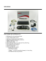
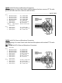
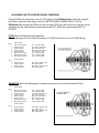
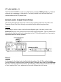
RIGblaster Pro Top of the line single radio interface to a PC with Rig control OWNER’S MANUAL http://www.westmountainradio.com 1020 Spring City Drive, Waukesha, WI 53186 tel 262.522.6503 fax 262.522.6504 [email protected] 2011 PREFACE Thank you for buying the RIGblaster Pro. Whether you are upgrading from another RIGblaster, another sound card interface, or this is your first interface, we think you will be pleased with the capabilities of the Pro. This model includes rig control and numerous panel controls and connections for maximum operating flexibility. For basic Amateur Radio sound card operation the RIGblaster Pro is easier to set up and operate than any other sound card interface. Front panel status indicators show at a glance, signal routing, audio signal level and activation of PTT, CW and FSK control and keying. The cable hookups remain similar to all other models of RIGblasters. The RIGblaster Pro flexibility provides, for example, four ways to connect to receive audio. This user manual will explain the additional connection and configuration options for full functionality. Feel free to try all the possible functions of the RIGblaster Pro one at a time or all at once depending on your desire to experiment. In the spirit of Amateur Radio, that is what it is all about! CHOOSING A MOUNTING LOCATION The supplied microphone cable is 3 feet long and the computer cables are 6 feet long. Choose a location that allows these cables to reach the radio and PC. The computer cables may be extended within reason. The computer should be in operating position with the radio(s). Do not attempt to run the RIGblaster Pro with a computer across the room, especially if it is on a different house wiring circuit than your ham station. Regular operation will require access to the back panel. The top cover can be removed without disconnecting the cables for easy access to the internal jumpers. When using a hand microphone with a coiled cord, consider the tug on the cord. Use the supplied double stick pads to prevent the RIGblaster Pro from being tugged out of place. Locate the RIGblaster Pro at least 18 inches away from anything that can have a strong magnetic field, such as transformer type power supplies, amplifiers, CRT type monitors or rotor control boxes. Do not put the RIGblaster Pro in strong RF fields. The RIGblaster Pro requires little or no ventilation and can be put anywhere that does not block the ventilation for another piece of equipment that does require ventilation. TABLE OF CONTENTS PREFACE.................................................................................................................................. 1 PLEASE NOTE: ......................................................................................................................... 2 UNPACKING ............................................................................................................................. 3 PANEL DESCRIPTION ............................................................................................................. 4 FRONT PANEL ...................................................................................................................... 4 REAR PANEL ........................................................................................................................ 5 INSTALLATION & CONNECTIONS .......................................................................................... 7 STEP 1 - INSTALL SOFTWARE AND START RECEIVING .................................................. 7 STEP 2 - INSTALL JUMPERS and CONNECT MIC CABLE ................................................. 8 STEP 3 - CONNECT SERIAL CABLE(S)............................................................................... 8 STEP 4 - CONNECT AUDIO CABLES ................................................................................ 10 STEP 5 - SET AUDIO LEVELS ............................................................................................ 11 STEP 6 - CW CABLING AND SETUP ................................................................................. 13 STEP 7 - FSK CABLING AND SETUP ................................................................................ 13 STEP 8 - RIG CONTROL CABLING AND SETUP .............................................................. 13 STEP 9 - ADVANCED AUDIO PROCESSING CONSIDERATIONS ................................... 16 STATION HOOKUP DIAGRAM (basic sound card function) .................................................. 17 STATION HOOKUP DIAGRAM (all features & functions) ....................................................... 20 MICROPHONE JUMPER DIAGRAMS .................................................................................... 23 8 PIN SCREW ON MICROPHONE JUMPERING ................................................................ 23 RJ45 MODULAR STYLE MICROPHONE JUMPERING ...................................................... 25 RECEIVE AUDIO AVAILABLE ON THE MIC CONNECTOR ............................................... 26 MIC MODE JUMPER – P6................................................................................................... 27 COM PORT & RIG CONTROL JUMPER DIAGRAMS (P16)................................................... 28 PTT LOOP JUMPER – P5 ................................................................................................... 30 RECEIVE AUDIO CONNECTION OPTIONS .......................................................................... 30 RIGblaster Pro TROUBLESHOOTING TIPS ........................................................................... 32 INDEX...................................................................................................................................... 34 PLEASE NOTE: This manual will refer to the sound device on a computer as “Sound Card”. Although many computer sound devices are integrated onto the motherboard of the computer, the term will be used as a general description. The words “Radio”, “Transceiver” and “Rig” as used within this document are synonymous. Also “c.s.” as used throughout this document means audio generated by the sound card, or Computer Sound. UNPACKING Items included with the RIGblaster Pro 1 - RIGblaster Pro Unit and Cover Screws 1 - Power Supply Isolated 12VDC 1 - RIGblaster & RIGtalk Software Collection 1 - Microphone Cable (RJ45 to 8 pin screw on) 1 - DB9M to DB9F Serial Cable 1 - USB Interface Cable 6 - Stereo Audio 6ft. Patch Cord (1/8 inch/3.5mm Mini Plug) 1 - Set of Instant Set-up Connectors 1 - Owners Manual (not pictured) 1 - Patch Cord Label Set 1 - Accessories Kit (that contains) 11 White Wire Jumpers 6 Blue Shunt Jumpers 1 Adapter – 1/8 inch (3.5mm) Mini (female) to 1/4 inch Plug 4 3M Adhesive Pads (not pictured) PANEL DESCRIPTION FRONT PANEL - MICROPHONE CONNECTOR, 8-Pin Screw-on Microphone Connector – connects the radio microphone to the RIGblaster Pro. (May be used as mic out on a radio with an RJ45 microphone connector) - “mic 2”, an auxiliary mic connector for connecting a microphone with a 1/8 inch (3.5mm) connector. Main mic does not need to be disconnected as this jack switches over automatically. - COMPUTER MONITOR HEADPHONE JACK – Accepts Headphones with a ¼ inch Jack - COMPUTER MONITOR HEADPHONE JACK – Accepts Headphones with a 1/8 inch (3.5mm) Jack - “level set” – For adjusting the audio level being fed from the PC audio Line Out or headphone out to the Mic input of the attached radio in order to set transmit drive level. - “level” LED – A Green LED that indicates the presence of sound card audio in Receive Mode. In Transmit mode, it indicates sufficient sound card audio to adequately modulate most radios. - “c.s.” LED – A Green LED, when on, indicates computer sound (c.s.) is being fed to the radio. When this LED is on, the direct microphone path to the radio is disconnected. - “mic” LED – A Green LED, when on, indicates the microphone is available to the radio. See STEP 9 ADVANCED AUDIO PROCESSING CONSIDERATIONS later in this manual for more information. - “process” LED – A Yellow LED indicating that the RIGblaster Pro is in Process Mode This LED will turn on only when the “Process Switch” is on and PTT is pressed on the attached mic or via an attached PTT switch/foot switch or when PTT is activated by software through the serial port connection from the PC. - “process” Switch – Turns process mode on or off. Up is ON and down is OFF. This switch must be OFF when the RIGblaster Pro is turned off for the mic to work normal. If the “Process Switch” is OFF, microphone audio is fed directly to the radio. When the “Process Switch” is ON, mic audio can be connected via the RIGblaster Pro to the PC mic input and back into the radio. Please see STEP 9 ADVANCED AUDIO PROCESSING CONSIDERATIONS later in this manual for more information about Process Mode. - “ptt” LED – This Red LED indicates when PTT is activated the your mic, foot switch or by software through the serial port connection from the computer. FRONT PANEL continued - “cw” LED – This Red LED indicates when CW keying is active with appropriate software for CW keying. This LED may be on with the RIGblaster Pro turned off if the serial port to the PC is connected and the DTR line of that serial port is active. - “fsk” LED – This Red LED blinks when FSK keying is active with appropriate software for FSK keying. Under certain conditions, this LED may be on without an active FSK program running on the PC if the serial port to the PC is connected and the TXD line of that serial port is in an up state. This condition can also occur with some USB to serial port converters. - “power” SWITCH – Turns power ON and OFF. Up is ON and down is OFF. - “power” LED – a Green LED indicating the RIGblaster Pro is turned on. REAR PANEL - POWER INPUT – 12 VDC Input – connects the Supplied Power Supply to the RIGblaster Pro. COMPUTER: SERIAL CONTROL - SERIAL/COM RS232 IN/OUT B – DB9 - For connection to a second available PC serial port or USB Interface Cable. This is the secondary jack and depending on the software you wish to run, this may be used for ONLY ONE of the following functions: FSK keying (if SERIAL/COM RS232 IN/OUT A is being used for Rig Control) Rig Control (if SERIAL/COM RS232 IN/OUT A is being used for FSK) Rig Control pass through from SERIAL/COM RS232 IN/OUT A (only if the radio has a DB9 Rig Control jack) - SERIAL/COM RS232 IN/OUT A – DB9 - For connection to an available PC serial port or USB Interface Cable. This is the primary jack and depending on the software preferred, this may be used for ONLY ONE of the following combination of functions: PTT Control, CW Keying and Rig Control PTT Control, CW Keying and FSK Keying See COM PORT & RIG CONTROL JUMPER DIAGRAMS later in this manual. RIG: CONTROL & KEYING - CTL. IN/OUT – 1/8 MINI JACK - for connection to ICOM or TenTec radios with a CI-V REMOTE CONTROL JACK for controlling ICOM or TenTec radios with appropriate Rig Control software. This jack is also used to connect to Yaesu radios that have DIN jack TTL CAT capability for controlling Yaesu radios with appropriate Rig Control software. Specific jumpering on the P16 jumper block inside the RIGblaster Pro is required for ICOM, TenTec or Yaesu radios. When jumpered for ICOM radios, both transmitted and received data are on the tip in relation to the sleeve and there is no connection to the ring. When jumpered for Yaesu, received data from the radio is on the tip and transmitted data to the radio is on the ring, both are in relation to ground on the sleeve. See COM PORT & RIG CONTROL JUMPER DIAGRAMS later in this manual for additional information about Rig Control. - CW OUT – 1/8 MINI JACK - for connection to the CW straight key jack on your radio for computer CW keying with appropriate software. Compatible with solid state radios that key with positive pull down. - FSK OUT – 1/8 MINI JACK - for connection to the FSK input of your radio for computer FSK keying with appropriate software. Compatible with solid state radios that key with positive pull down. COMPUTER: AUDIO - MIC OUT – 1/8 MINI JACK - for connection to Mic In on a desktop PC. (May not apply to LapTop Computers where Mic In is used for Receive Audio input to the computer soundcard) This provides the path for connecting your radio microphone to your computer sound Mic In. This output must be activated with the jumper on the P6 jumper block. See the section titled MIC MODE JUMPER – P6 later in this manual. - SPKR OUT – 1/8 MINI JACK - Plug PC speakers into this jack. - LINE IN – 1/8 MINI JACK - for connection to the computer sound Line Out. (Speaker Out for un-amplified computer speakers, headphone out for a LapTop) - LINE OUT – 1/8 MINI JACK – for connection to the computer sound Line In. (Mic In on LapTops) RIG: AUDIO/PTT - AUDIO IN – 1/8 MINI JACK – for connection to either fixed or variable line or speaker level audio from the radio. Not used if receive audio is taken directly from the P1 jumper block. See the section titled RECEIVE AUDIO AVAILABLE ON THE MICROPHONE CONNECTOR later in this manual. - SPKR OUT – 1/8 MINI JACK – for connection of the radio external speaker. Used in cases where the radio external speaker output is used to supply audio to the computer sound Line In. If using fixed or line level audio from the radio to AUDIO IN, no. 11 above, this jack will not be used. - PTT OUT – RCA PHONO JACK – for connection of the external PTT switch or PTT foot switch. This jack, as well as the PTT IN jack, may be separated and used for connection to an external sequencer. See the section titled PTT LOOP JUMPER - P5 later in this manual. - PTT IN – RCA PHONO JACK – for connection of the external PTT switch or PTT foot switch. This jack, as well as the PTT OUT jack, may be separated and used for connection to an external sequencer. See the section titled PTT LOOP JUMPER - P5 later in this manual. - MIC OUT – RJ45 MODULAR JACK – for connection to the Microphone connector on the radio. This connection is made using the included Mic Cable. (May be used as mic in for a radio with an RJ45 microphone connector.) Note: References used throughout this document, such as (R15) refer to the RIGblaster Pro Switch, Connector, Knob, Jack or LED as illustrated on these PANEL DESCRIPTION pages. Example; “This connection is made to the MICROPHONE OUTPUT (R15) on the RIGblaster Pro”. (R15) refers to Rear Panel illustration number to quickly locate this particular Switch, Connector, Knob, Jack or LED. INSTALLATION & CONNECTIONS STEP 1 - INSTALL SOFTWARE AND START RECEIVING The RIGblaster Pro is not needed to receive so leave it in the box! Placed the included CD ROM into the CD drive. If the PC does not auto-run the CD, click on My Computer to locate the drive and double click on the CD drive. The West Mountain Radio screen will pop up in a few seconds. Now click on the “XMIT” button for the “West Mountain Radio RIGblaster Software Collection”. Choose one of the programs to try and follow the installation prompts that appear on the screen to install the software. An icon will be placed on the desktop to execute this software in the future without the need of this CD. Keep the CD for future reference. The software can also be executed from the Windows task menu by clicking “Start”>“Programs”, and select to execute that program. Using one of the supplied mini plug cables, (referred to throughout this manual as “Patch Cord”) connect the speaker output of the radio to the Line In (Mic In on a laptop) to the PC. There are three other receive audio connection options that will be described later in this manual. Tune in an appropriate signal for the mode selected. On the CD, is a chart of standard operating frequencies for the various modes. For a better understanding of what to listen for when tuning, the CD also contains recordings of many of these exciting new modes. Double click the little yellow speaker icon in the lower right corner of the Windows screen. The Windows sound playback control panel will open. Click “Options”> “Properties”> “Recording”> “OK” to get the recording control panel. With the mouse, turn up the “Line In” slider (or “Microphone In” on a laptop) about half way and click “Select”. Turn up the radio volume control (AF Gain) to the 9 or 10 o’clock position or until a signal is displayed on the ham radio sound card software screen. Follow the instructions or Help provided with each software program to tune in the station by using the radio and/or software. Try tuning in several other stations or even try another program or mode. NOTE: Before proceeding beyond this step, disconnect the audio cable installed above. STEP 2 - INSTALL JUMPERS and CONNECT MIC CABLE Jumpers are not installed as shipped; they are packed separately (see Items included with the RIGblaster Pro on Page 3). The unit cover must be removed to install jumpers, see MICROPHONE JUMPERING and SERIAL PORT & RIG CONTROL JUMPER DIAGRAMS in the back of this manual. These jumpers are necessary so that the RIGblaster Pro microphone pin assignments will match the different microphone pin assignments of various radio equipment manufacturers such as Icom, Yaesu, Kenwood, Alinco, TenTec, Elecraft, etc.. After the jumpers are installed for the specific radio, connect the supplied Mic Cable in one of the following manners: FOR RADIOS WITH A STANDARD 8 PIN SCREW ON MICROPHONE CONNECTOR Using the supplied 3 foot mic cable connect the end with the RJ45 connector to MIC OUT (R15) on the rear of the RIGblaster Pro. Connect the other end to the Mic Connector on the radio. Then plug the radio microphone into MICROPHONE CONNECTOR (F1) on the front panel of the RIGblaster Pro. FOR RADIOS WITH AN RJ45 MICROPHONE CONNECTOR Using the supplied 3 foot mic cable connect the end with the RJ45 connector to Mic Connector on the radio. Connect the other end to the to MICROPHONE CONNECTOR (F1) on the front panel of the RIGblaster Pro. Then plug the radio microphone into MIC OUT (R15) on the rear of the RIGblaster Pro. Make sure the RIGblaster Pro Power Switch (F14) is turned off. Now plug the wire from the Power Supply into the Power Jack (R1) on the rear panel of the RIGblaster Pro. Plug in the Power Supply, turn off the RIGblaster Pro Process Switch (F10), and then turn on the RIGblaster Pro Power Switch (F14). The Green “Power” LED (F15) and the Green “mic” LED (F8) should come on. The Green “level.” LED (F6) will come on briefly then will go off. Jumper installation is correct if everything on the mic works correctly, including an on-the-air audio report. If there a problem, refer back to the jumper diagram that matches the mic being used, not necessarily the radio. After market mics, especially Yaesu may not have exactly the same wiring as the original radio mic. When all aspects of the mic work correctly, continue to the next step. STEP 3 - CONNECT SERIAL CABLE(S) **READ THIS ENTIRE SECTION BEFORE PERFORMING THE STEP** Turn off the RIGblaster Pro Power Switch. The Green “Power” LED and the Green “mic” LED should go off. Turn off THE radio and PC before connecting any cables to either. If your PC does not have a real Serial Port, use the included USB Interface Cable. To install the drivers necessary to use the USB Interface Cable, please see the “RIGblaster Pro USB Owners Manual Addendum” at the rear of this manual. One DB9 Male to DB9 Female Serial Cable is supplied with the RIGblaster Pro. The specific software and the manner in which intended operation of the various functions facilitated by the RIGblaster Pro will determine how to connect the serial cables. To do basic SoundCard applications such as PSK31, SSTV, CW, RTTY, connect the supplied serial cable between an available serial port on the PC and SERIAL/COM RS232 IN/OUT A (R3) on the rear of the RIGblaster Pro. Read the section titled COM PORT & RIG CONTROL JUMPER DIAGRAMS to assist in determining if a second serial cable (not supplied) is need between a second serial port on the PC and SERIAL/COM RS232 IN/OUT B (R2) on the rear of the RIGblaster Pro. Additional DB9 to DB9 Serial Cables can be purchased from West Mountain Radio at www.westmountainradio.com. Turn on the RIGblaster Pro Power Switch. The Green “Power” LED and the Green “mic” LED should come on. The Green “level.” LED (F6) will come on briefly then will go off. At this time no other LED should light. Turn on the PC. During the boot-up process, the PTT LED (F11) will blink on and off at least once. The CW LED may also blink on and go off during the boot-up. When the booting is complete, the PTT and CW LEDs should be off. If not, there is a software problem; see the Support pages online at www.westmountainradio.com/support. (Note: This test may or may not work if using the USB Interface Cable in place of a real serial port.) This test confirms that the cable, the computer serial port, and the PTT circuitry in the RIGblaster Pro are working properly together. Look for additional information on the support pages if using Windows/ME. www.westmountainradio.com DO NOT proceed to the next step of the installation if this step FAILS. (Except when using USB Interface Cable.) STEP 4 - CONNECT AUDIO CABLES **READ THIS ENTIRE SECTION BEFORE PERFORMING THE STEP TO DETERMINE WHICH STEPS MAY BE SKIPPED** Turn off the RIGblaster Pro Power Switch. The Green “Power” LED and the Green “mic” LED should go off. Turn off the radio and PC before connecting cables to either unit. Six (6) 1/8 inch Stereo Mini Plug Patch Cords (“patch cords”.) are supplied with the RIGblaster Pro. The software and the manner in operating the various functions facilitated by the RIGblaster Pro will determine the number and where to connect these patch cords. Additional 1/8 inch Stereo Mini Plug Patch Cords can be purchased from West Mountain Radio www.westmountainradio.com. It is recommended to label each patch cord at the end before installation. ROUTING: TRANSMIT COMPUTER AUDIO RIGblaster Pro Computer Speakers On a PC, unplug the computer speakers from the computer and plug them into SPKR OUT (R8) on the rear of the RIGblaster Pro. Then plug one end of a patch cord to the jack on the PC where the computer speakers were plugged. Plug the other end of that patch cord to LINE IN (R9) on the rear of the RIGblaster Pro. On laptop computers with only two audio jacks, plug one end of a patch cord to the headphone jack of the laptop computer and plug the other end of that patch cord to LINE IN (R9) on the rear of the RIGblaster Pro. ROUTING: RECEIVE RADIO AUDIO RIGblaster Pro Computer Sound, Line In Three methods are available for obtaining audio from the radio to a PC. The method to choose will primarily depend on the options available on each radio. If a radio has the provision for connecting an external speaker, but no other means of getting audio out of the radio, then Method 1 should be used. If a radio has fixed level audio available from the rear panel via an accessory socket, then Method 2 is recommended. If a radio has output audio available at the mic connector, RIGblaster Pro has the capability to use this as a source for audio input to the PC, thus using Method 3. In all three methods, RIGblaster Pro will provide DC isolation for receive audio between the radio and the PC. Method 1: An external speaker will be needed for the radio. Plug one end of a patch cord to the External Speaker Output jack of the radio and the other end to AUDIO IN (R11) on the rear panel of the RIGblaster Pro. Then plug the radio external speaker into SPKR OUT (R12) on the rear panel of the RIGblaster Pro. Plug one end of a patch cord to LINE OUT (R10) on the rear panel of the RIGblaster Pro and plug the other end to Line In on the computer sound. Method 2: This method requires a special cable, one end of this cable will have a mini plug (like the provided patch cables)and the other end will be a connector that will plug into the source of fixed level audio on your radio (possibly labeled Data Out, Monitor Out, Record Out, Patch Out, etc.) and may be a DIN plug, a mini DIN plug, RCA plug, etc. Consult the radio Owners Manual for the required connector. West Mountain Radio has several cables available to purchase to mate to many popular radios of Icom, Kenwood and Yaesu. See www.westmountainradio.com. Plug the mini plug end of this cable to AUDIO IN (R11) on the rear panel of the RIGblaster Pro. Plug the other end of this cable to the connector to the radio that provides fixed level audio as outlined in the previous paragraph. Plug one end of a patch cord to LINE OUT (R10) on the rear panel of the RIGblaster Pro and plug the other end to Line In to the computer sound. When using Method 2, there will be no connection to SPKR OUT (R12) on the rear of the RIGblaster Pro. Method 3: Audio is supplied to the RIGblaster Pro through the Mic Cable previously installed in Step 1. On some radios, output audio is available on a radio mic connector pin. This can be utilized on the P1 jumper block inside the RIGblaster Pro. See the example under “MICROPHONE PIN ASSIGNMENTS (example)” later in this manual. Consult the microphone pin assignment diagram in the Owners manual of the radio to determine which pin on the mic connector will correlate to the pin on the P1 jumper block in order to jumper to RCV AUD and RCV AUD GND. For example, on the radio model IC-756PRO, the Microphone Pin Assignments outlined later in this manual, shows pin 8 is used for receive audio. Pin 8 is jumpered to RCV AUD on the OUTPUT side of the P1 jumper block to provide receive audio to the RIGblaster Pro. Ground reference must also be provided by jumpering RCV AUD GND on the INPUT side to GNDTIE on the INPUT side also on the P1 jumper block. On Icom radios this audio is not fixed, it is variable with the AF Gain control. After completing the necessary jumpering on the P1 jumper block, plug one end of a patch cord to LINE OUT (R10) on the rear panel of the RIGblaster Pro and plug the other end to Line In to the computer sound. STEP 5 - SET AUDIO LEVELS Begin with the Radio turned OFF. Open the Windows sound control panel (double click on the little yellow speaker icon in the task bar) and un-mute the “wave” output and the left hand “Volume Control” output. Set the virtual “Volume” and “Wave” sliders to a position one notch down from the top. Also set the virtual balance sliders to the center. If computer speakers are hooked up and they have a volume control knob, turn that knob down, but not completely off. In the case there is not a volume knob, the speakers may be too loud and consider turning them off after verifying the sound card level is high enough for the speakers to be at a comfortable level. Turn ON the RIGblaster Pro, the “process” Switch (F10) is OFF, and the “level set” Knob (F5) is all the way counterclockwise. Set the software to Transmit or Tune. The RIGblaster Pro “c.s.” LED (F7) and “ptt” LED (F11) should be ON. If using software, such as WinPSK, that will bring up both RTS and DTR when set to transmit, the CW LED (F12) may also come on. If these LEDs do not come on, recheck the serial port software setting for PTT control. The RIGblaster Pro PTT is always controlled with the RTS. If the “c.s” and “ptt” LEDs are on, then the “level” LED (F6) should also be ON, indicating there is sufficient audio from the sound output of the PC being delivered to the RIGblaster Pro to adequately modulate the radio. Now refine the wave output setting on the Windows sound control panel to the point just past the “level” where the LED has just come on. Set the software back to Receive. Turn ON the radio for the remainder of this procedure. Use your normal mic gain setting for SSB radios. Turn OFF the speech compressor and set the transmitter RF drive (power control) all the way up. Start with a dummy load for this procedure. If using PSK software, make sure that the transmit audio is between 500Hz and 2500 Hz, otherwise it may be outside the limits of the response of the radio causing transmit problems. Set the software to Transmit or Tune. Then slowly turn up the “level set” Knob (F5) on the front of the RIGblaster Pro to the point where the ALC just starts to move or a normal RF power output is achieved. The final setting must produce less than full RF power output from your radio. Warning: Do not exceed the AM, FM or RTTY power rating of the radio. After this setting is completed, check to ensure the ALC meter is below limiting. Even if the radio is rated at full output and continuous duty, do not set the audio to full output. Take care that if running the computer sound output at maximum or close to maximum, and the RIGblaster Pro “level set” turned way down, there may be distortion from the computer sound and a poor quality signal. Generally the wave and volume sliders should be between 1/3 and 2/3 open and the RIGblaster Pro “level set” knob should be between 1/8 and 7/8 open. With an FM rig, set the audio level with the “level set” knob using a deviation meter or by comparing the level of the transmit audio to other stations using another radio. For a more information about Computer Sound Cards, see the article titled “The In’s and Out’s of a Sound Card” in October 2003 QST. Also available in PDF format on our Web Site at: http://www.westmountainradio.com/pdf/Ins&Outs.pdf STEP 6 - CW CABLING AND SETUP Turn off both the radio and the RIGblaster Pro before connecting cables to either unit. Plug one end of a patch cord to the CW OUT (R5) jack on the rear panel of the RIGblaster Pro. Plug the other end into the CW Key jack to the radio. If the CW Key jack on the radio is a 1/4” jack, it will be necessary to use the supplied 1/8” to 1/4” adapter. For computer CW it is necessary to make sure the radio CW keying is set for “Straight Key” mode for the jack in use. The remaining setup for PC controlled CW will be done in the application software you choose. Control of CW is not selectable and will always be done through Serial/Com RS232 In/Out A, with the DTR line. Observe this convention when configuring the software. On the CW OUT (R5) jack, the sleeve goes to common ground and the tip goes to the keying circuit, the ring of this connector is not used. STEP 7 - FSK CABLING AND SETUP Turn off both the radio and the RIGblaster Pro before connecting cables to either unit. In order to utilize FSK/RTTY, the radio must have this capability. FSK wiring is unique to each Amateur Radio transceiver manufacturer. Therefore, consult the specific radio Owners Manual for information for how to connect to the FSK input. For many radios, the FSK connection is via an accessory connection on the rear panel of the transceiver. West Mountain Radio has a ready-made cable for a connection between the RIGblaster Pro and the FSK input of many Icom, Kenwood and Yaesu radios. View the RIGblaster Accessories at: http://www.westmountainradio.com by clicking on the RIGblaster model and the Accessories tab. After making or purchasing the correct FSK cable, connect the mini plug end to FSK OUT (R6) on the rear panel of the RIGblaster Pro. Connect the other end of this cable to the appropriate connection on the transceiver. Always check the wiring prior to connecting homemade cables to any equipment. On the FSK OUT (R6) jack, the sleeve goes to common ground and the tip goes to the FSK keying circuit, the ring of this connector is not used. Refer to section COM PORT & RIG CONTROL JUMPER DIAGRAMS for any necessary jumpering on the P16 jumper block that may be required. In most cases, operation of the radio in RTTY mode is needed to enable FSK input. STEP 8 - RIG CONTROL CABLING AND SETUP Note: RIG Control cabling and jumpering differ depending on the radio manufacturer. Most Icom and TenTec radios (with CI-V) use a single bi-directional conductor, thus, requiring a standard patch cord to connect the RIGblaster Pro and the radio. Hook up an ICOM or TenTec (with CI-V) radio to a RIGblaster Pro by connecting one end of a patch cord to CTL IN/OUT (R4) on the rear of the RIGblaster Pro. Connect the other end to the “CI-V REMOTE CONTROL JACK” on the rear of the ICOM or TenTec radio. The factory setting of jumpering on the P16 Jumper Block is already set for ICOM/TenTec Rig Control through SERIAL/COM RS232 IN/OUT A. Specific jumpering on the P16 jumper block inside the RIGblaster Pro is required for ICOM, TenTec, or Yaesu radios. When jumpered for ICOM radios, both transmit and receive data are on the tip in relation to the sleeve and there is no connection to the ring. When jumpered for Yaesu, receive data from the radio is on the tip and transmit data to the radio is on the ring, both are in relation to ground on the sleeve. See COM PORT & RIG CONTROL JUMPER DIAGRAMS later in this manual for additional information about Rig Control. A Yaesu can be more complicated. The Yaesu CAT system uses three wires and have different connectors and pin wiring arrangements between different models. Older Yaesu radios require the rig control TTL (5 volt) to RS232 level converter built into the RIGblaster Pro. See below for additional information that applies specifically to the Yaesu FT-990 & FT1000D. Older Yaesu CAT systems require that the RIGblaster Pro rig control jumper P16 be set to Yaesu. The patch cord plug must be changed to match the Yaesu DIN jack. Be sure that the tip of the patch cord plug comes from the data out of the radio and the Ring goes to the data in to the radio. West Mountain Radio has two CAT Cables available for Yaesu radios. Older Kenwood radios that have provisions for TTL control are not possible to control with a RIGblaster Pro. These Kenwood radios utilize what is referred to as Negative TTL Logic and are not compatible with the Positive Logic employed in the RIGblaster Pro TTL to RS232 converter. Positive logic, as employed in most computer interface circuitry, represents a logical one with a positive voltage and a logical zero with a zero voltage. To connect a RIGblaster Pro to Yaesu radios with a 6 pin DIN receptacle with TTL level CAT control, the following cable would need to be constructed. Pin numbers vary within Yaesu models, but GND is usually numbered pin 1. If using a Yaesu or other brand of radio with an RS232 Rig/CAT control jack do not use the rig control output. Instead, use the RIGblaster Pro's RXD & TXD on A passed through to B option (#9 on the P16 Jumper block). This will allow both sound card operation, PTT, CW and rig control with a single serial port with software such as HamScope, MixW or WriteLog. If it is desired to use separate sound card and rig control programs at the same time, a direct connection from the PC to the radio's RS232 control jack will be needed. If the radio is equipped with a FEMALE DB-9 RS232 connector for Computer Control (CAT), the following cable will be necessary from the B Port on the RIGblaster Pro to the radio RS232 DB-9. Both DB-9 connectors shown here are MALE connectors. If using a newer Kenwood (Example TS-570/870/2000) radio or an Icom IC-7800 with a MALE RS232 CAT/Rig Control jack do not use the CTL IN/OUT jack on the RIGblaster Pro. It is possible to use the RIGblaster Pro for both sound card operation, PTT, CW and FSK To do CAT on these radios, use the Optional DB9M to DB9F Serial/Extension Cable (or equivalent) connected directly to an available serial port on the PC or to a USB jack on the PC with a USB Interface Cable (or equivalent USB to Serial Port Adapter.) For some radios it may be necessary to connect pins 7 and 8 on the receiver end as illustrated above. This is necessary to fool the radio into thinking it sees Clear To Send (CTS) in response to it raising Request To Send (RTS). These lines are not passed through the RIGblaster Pro as they are used for other functions within the RIGblaster Pro. Note: not all programs will do rig control on the same serial port that does PTT and CW. Yaesu FT-990 & FT-1000D with TTL CAT ports use an emitter follower with a high impedance driver on the SO (serial out) line. This is not a problem when driving Yaesu's FIF232C which uses an optical isolator. However, when driving a TTL or CMOS gate (7408, MAX232, etc.) as used in RIGblaster Pro, the emitter follower does not provide enough load to pull input of the buffer/converter low (< 0.5 volt) in the off state. This prevents it from transferring data from the radio to the computer. Yaesu recognized the problem and added a 1.5K resistor from SO to ground in later production of the FT-990 & FT-1000D and other radios using a similar circuit. In practice any resistor between 1 K and 4.7K will probably work. There is a very quick way to determine if your Yaesu is effected ... turn off the radio and measure resistance from pin 2 (SO) and pin 1 (ground) of the CAT jack. If measure less than 5 K Ohms, then add a 1.5 K or 2.2 K resistor inside the radio or externally between those two pins. STEP 9 - ADVANCED AUDIO PROCESSING CONSIDERATIONS A unique feature of the RIGblaster Pro is that it is possible to process, equalize, compress or expand transmitted audio. This is done simply by routing your microphone audio into your computer and back out to your radio while processing the audio (real time) with appropriate sound card software. In order to enable this feature and begin to make digital recordings of station operation, plug the jumper on the P6 Jumper Block to send the microphone audio to the PC. See the section labeled “MIC MODE JUMPER – P6” later in this manual for jumpering diagrams. A cable from the RIGblaster Pro MIC OUT (R7) to the Computer Sound Card MIC IN is also needed to enable this feature. The PC must have an available Mic In and must have a full duplex sound card that will pass the sound card microphone input through software and then back out to the RIGblaster Pro. To enable microphone audio processing, turn on the “process” switch (F10). The function of process mode is to redirect audio from the radio microphone through the PC and back to the radio. Process Mode of the RIGblaster Pro to process the audio from the radio microphone is enabled by utilizing appropriate real time equalization software on the PC and set the sound card recording control panel to feed microphone audio through the software, and then the sound card playback control panel to send the audio back in to the radio through the RIGblaster Pro. Note that this is a different sound card setup than is used by digital mode sound card programs. Also note that if the sound card is set incorrectly there could be feedback and/or echo conditions. Voice is not heard coming from the PC speakers, as they are muted on transmit in the process mode to prevent acoustic feedback. The gain of the sound card input and output will need to be set for minimum distortion and minimum noise by determining the optimum settings for equipment. Do the basic setup with the equalizer software set to “flat”. When satisfied that the microphone is being passed through the PC with little or no change, then experiment with equalization of the microphone audio. Equalization control in the voice spectrum of 100 to 3500 Hz will have a noticeable effect on voice. Trying to boost equalization outside of this spectrum may overdrive the sound card or radio audio stages with microphone handling and room noises. It is generally desirable to totally cut or filter out the frequencies outside the voice spectrum range. Take into consideration that equalization can be done in any way to make the audio sound either better or worse. Attempt to achieve the most intelligible audio for DXing and general communication. Wideband FM or AM operation prefer the most natural audio for a high fidelity sound. If using compression or noise reduction software, all of the same issues of doing equalization are present. STATION HOOKUP DIAGRAM (basic sound card function) See next page for a description of each numbered wire on this diagram. The diagram on the preceding page shows a RIGblaster Pro integrated into an Amateur Radio Station consisting of a Professional Quality Transceiver and a Desktop Computer with a Serial Port and a Sound Card. With appropriate software, it enables most Amateur Radio Sound Card Software. For each numbered wire there is a description of its function and the end points to which it connects. - The station microphone is connected to the Microphone Connector (F1) on the front of the RIGblaster Pro. - This cable is a DB9M to DB9F Serial Cable or USB Interface Cable (supplied with RIGblaster Pro) It connects the RIGblaster Pro SERIAL/COM RS232 IN/OUT A (R3) port to the Computer serial port or USB jack. It is used for one and only one of the following combinations of function: PTT Control, CW Keying and Rig Control PTT Control, CW Keying and FSK Keying - This wire connects the Computer Speakers to the RIGblaster Pro. One end plugs into the SPKR OUT (R8) jack on the rear of the RIGblaster Pro. The other end remains as it was before, that is, connected to the Computer Speakers. - This is a mini plug Patch Cord that connects the Computer Sound Card - Line Out to the RIGblaster Pro. One end plugs into the LINE IN (R9) jack on the rear of the RIGblaster Pro. The other end plugs into the Line Out jack on the Computer Sound Card. - This is a mini plug Patch Cord that connects the Computer Sound Card - Line In to the RIGblaster Pro. One end plugs into the LINE OUT (R10) jack on the rear of the RIGblaster Pro. The other end plugs into the Line In jack on the Computer Sound Card. - This is a mini plug Patch Cord that routes receive audio from the Radio to the RIGblaster Pro. It provides a path for audio from the radio to the computer. One end plugs into the AUDIO IN (R11) jack on the rear of the RIGblaster Pro. The other end plugs into the EXTERNAL SPEAKER JACK on the transceiver. - This wire connects the Radio External Speaker to the RIGblaster Pro. One end plugs into the SPKR OUT (R12) jack on the rear of the RIGblaster Pro. The other end remains as it was before, that is, connected to the Radio External Speaker. - This is the Microphone Cable (supplied with the RIGblaster Pro) that connects the RIGblaster Pro to the Microphone Input jack of the transceiver. The end with the RJ45 connector plugs into the MIC OUT (R15) jack on the rear of the RIGblaster Pro. The end with the standard 8-pin Screw on Mic Connector plugs into the MICROPHONE CONNECTOR on the transceiver. - This wire, from the Power Supply (supplied with the RIGblaster Pro), provides power for the RIGblaster Pro. It plugs into the POWER 12VDC (R1) jack on the rear of the RIGblaster Pro. STATION HOOKUP DIAGRAM (all features & functions) See next page for a description of each numbered wire on this diagram. The diagram on the preceding page shows a RIGblaster Pro integrated into an Amateur Radio Station consisting of a Professional Quality Transceiver and a Desktop Computer with two Serial Ports and a standard Sound Card. With appropriate software, it enables every function possible with a RIGblaster Pro. For each numbered wire there is a description of its function and the end points to which it connects. - The station microphone is connected to the Microphone Connector (F1) on the front of the RIGblaster Pro. - This cable is an optional DB9M to DB9F Serial Cable or USB Interface Cable (not supplied) and connects the RIGblaster Pro SERIAL/COM RS232 IN/OUT B (R2) port to the Computer secondary serial port or USB jack. It is used for one and only one of the following functions: FSK keying (if SERIAL/COM RS232 IN/OUT A is being used for Rig Control) Rig Control (if SERIAL/COM RS232 IN/OUT A is being used for FSK) Rig Control pass through from SERIAL/COM RS232 IN/OUT A (only if your radio has a DB9 Rig Control jack and you wish to use a program like HamScope or MixW that does Rig Control, CW, and PTT) - This cable is a DB9M to DB9F Serial Cable or USB Interface Cable (supplied with RIGblaster Pro) It connects the RIGblaster Pro SERIAL/COM RS232 IN/OUT A (R3) port to the Computer primary serial port or USB jack. It is used for one and only one of the following combinations of function: PTT Control, CW Keying and Rig Control PTT Control, CW Keying and FSK Keying - This is a mini plug Patch Cord that is used to interface the RIGblaster Pro to the Radio for Rig Control. One end plugs into the CTL IN/OUT (R4) jack on the rear of the RIGblaster Pro. The other end plugs into the CI-V REMOTE CONTROL jack on the rear of the transceiver. For CAT control with a Yaesu TTL jack, it is neccesary to supply the plug on the other end and change the jumpering on the P16 Jumper Block. See the section titled “COM PORT & RIG CONTROL JUMPER DIAGRAMS (P16) later in this manual. - This is a mini plug Patch Cord that is used to interface the RIGblaster Pro to the radio enabling the Computer to key the Radio in CW mode. One end plugs into the CW OUT (R5) jack on the rear of the RIGblaster Pro. The other end plugs into the STRAIGHT KEY JACK on the rear of the transceiver. - This is an optional Cable that is used to interface the RIGblaster Pro to the radio enabling the Computer to (FSK) key the Radio in RTTY mode. One end plugs into the FSK OUT (R6) jack on the rear of the RIGblaster Pro. The other end connects to the FSK keying input on the transceiver. For many Icom radios, this cable is available from West Mountain Radio as a RIGblaster Accessory. - This is a mini plug Patch Cord that is used to create the path for connecting the existing station microphone to the Computer Sound Card Mic In. One end plugs into the MIC OUT (R7) jack on the rear of the RIGblaster Pro. The other end plugs into the Mic In jack on the Computer Sound Card. See the section “MIC MODE JUMPER – P6” later in this manual and STEP 9 - ADVANCED AUDIO PROCESSING CONSIDERATIONS, earlier in this manual, for more information on using the radio mic on the PC. - This wire connects the Computer Speakers to the RIGblaster Pro. One end plugs into the SPKR OUT (R8) jack on the rear of the RIGblaster Pro. The other end remains as it was before, that is, connected to the Computer Speakers. - This is a mini plug Patch Cord that connects the Computer Sound Card - Line Out to the RIGblaster Pro. One end plugs into the LINE IN (R9) jack on the rear of the RIGblaster Pro. The other end plugs into the Line Out jack on the Computer Sound Card. - This is a mini plug Patch Cord that connects the Computer Sound Card - Line In to the RIGblaster Pro. One end plugs into the LINE OUT (R10) jack on the rear of the RIGblaster Pro. The other end plugs into the Line In jack on the Computer Sound Card. - This is a mini plug Patch Cord that routes receive audio from the Radio to the RIGblaster Pro. It provides half the path for DC isolated audio from the radio to the computer. One end plugs into the AUDIO IN (R11) jack on the rear of the RIGblaster Pro. The other end plugs into the EXTERNAL SPEAKER JACK [EXT SP] on the transceiver. - This wire connects the Radio External Speaker to the RIGblaster Pro. One end plugs into the SPKR OUT (R12) jack on the rear of the RIGblaster Pro. The other end remains as it was before, that is, connected to the Radio External Speaker. - This is the Microphone Cable (supplied with the RIGblaster Pro) that connects the RIGblaster Pro to the Microphone Input jack of the transceiver. The end with the RJ45 connector plugs into the MIC OUT (R15) jack on the rear of the RIGblaster Pro. The end with the standard 8-pin Screw on Mic Connector plugs into the MICROPHONE CONNECTOR [MIC] jack on the transceiver. - This wire, from the Power Supply (supplied with the RIGblaster Pro), provides power for the RIGblaster Pro. It plugs into the POWER 12VDC (R1) jack on the rear of the RIGblaster Pro. - This wire connects an existing PTT Foot Switch to the RIGblaster Pro. It plugs into the PTT IN- RCA Phono Jack (R14) on the rear of the RIGblaster Pro. MICROPHONE JUMPER DIAGRAMS 8 PIN SCREW ON MICROPHONE JUMPERING ALINCO, KENWOOD, SGC and ELECRAFT with 8 Pin Screw on Microphone Connectors INPUT SIDE Pin # 1 2 3 4 5 6 7 8 White Jumper to White Jumper to Blue Shunt Jumper to Blue Shunt Jumper to Blue Shunt Jumper to Blue Shunt Jumper to White Jumper to White Jumper to MIC – INPUT Side PTT – INPUT Side Pin 3 - OUTPUT Side Pin 4 - OUTPUT Side Pin 5 - OUTPUT Side Pin 6 - OUTPUT Side MIC GND – INPUT Side PTT GND – INPUT Side OUTPUT SIDE Pin # 1 2 7 8 White Jumper to White Jumper to White Jumper to White Jumper to MIC – OUTPUT Side PTT – OUTPUT Side MIC GND – OUTPUT Side PTT GND – OUTPUT Side ICOM with 8 Pin Screw on Microphone Connectors INPUT SIDE Pin# 1 2 3 4 5 6 7 8 White Jumper to Blue Shunt Jumper to Blue Shunt Jumper to Blue Shunt Jumper to White Jumper to White Jumper to White Jumper to Blue Shunt Jumper to MIC – INPUT Side Pin 2 - OUTPUT Side Pin 3 - OUTPUT Side Pin 4 - OUTPUT Side PTT – INPUT Side PTT GND – INPUT Side MIC GND – INPUT Side Pin 8 - OUTPUT Side OUTPUT SIDE Pin # 1 5 6 7 White Jumper to White Jumper to White Jumper to White Jumper to MIC – OUTPUT Side PTT – OUTPUT Side PTT GND – OUTPUT Side MIC GND – OUTPUT Side YAESU with 8 Pin Screw on Microphone Connectors (This jumpering is for older Yaesu radios with Microphones that have common PTT & audio ground and older hand mics, desk mics and Heil mics) ................................................................................................................................ INPUT SIDE Pin # 1 Blue Shunt Jumper to 2 Blue Shunt Jumper to 3 Blue Shunt Jumper to 4 Blue Shunt Jumper to 5 Blue Shunt Jumper to 6 White Jumper to 7 White Jumper to 8 White Jumper to GND TIE White Jumper to Pin 1 - OUTPUT Side Pin 2 - OUTPUT Side Pin 3 - OUTPUT Side Pin 4 - OUTPUT Side Pin 5 - OUTPUT Side PTT – INPUT Side PTT GND – INPUT Side MIC – INPUT Side GND TIE - OUTPUT Side OUTPUT SIDE Pin # 6 7 8 White Jumper to White Jumper to White Jumper to PTT – OUTPUT Side PTT GND – OUTPUT Side MIC – OUTPUT Side YAESU with 8 Pin Screw on Microphone Connectors (This jumpering is for newer Yaesu radios that have Microphones with isolated PTT & audio grounds.) JRC JST245 with 8 Pin Screw on Microphone Connectors INPUT SIDE Pin # 1 2 3 4 5 6 7 8 Blue Shunt Jumper to Blue Shunt Jumper to Blue Shunt Jumper to Blue Shunt Jumper to White Jumper to White Jumper to White Jumper to White Jumper to Pin 1 OUTPUT Side Pin 2 OUTPUT Side Pin 3 OUTPUT Side Pin 4 OUTPUT Side PTT GND – INPUT Side PTT – INPUT Side MIC GND – INPUT Side MIC – INPUT Side OUTPUT SIDE Pin # 5 6 7 8 White Jumper to White Jumper to White Jumper to White Jumper to PTT GND – OUTPUT Side PTT – OUTPUT Side MIC GND – OUTPUT Side MIC – OUTPUT Side RJ45 MODULAR STYLE MICROPHONE JUMPERING Plug the RJ45 mic in the back “mic out” (R16) jack of the RIGblaster Pro. Using the supplied mic Cable, screw the 8 pin plug in the front MICROPHONE CONNECTOR (F1) of the RIGblaster Pro and plug the RJ45 end into the radio RJ45 mic jack. Be sure to use the correct jumpering for the radio as follows and observe that PTT & MIC are crisscrossed INPUT to OUTPUT. ICOM with RJ45 Microphone Connectors (This jumpering is for Icom 706 (all versions), IC-7000 and most, but not all ICOM FM rigs INPUT SIDE Pin # 1 2 3 4 5 6 7 8 Blue Shunt Jumper to White Jumper to White Jumper to White Jumper to White Jumper to Blue Shunt Jumper to Blue Shunt Jumper to Blue Shunt Jumper to Pin 1 - OUTPUT Side PTT GND – INPUT Side MIC - OUTPUT Side * MIC GND – INPUT Side PTT - OUTPUT Side * Pin 6 - OUTPUT Side Pin 7 - OUTPUT Side Pin 8 - OUTPUT Side OUTPUT SIDE Pin # 2 3 4 5 White Jumper to White Jumper to White Jumper to White Jumper to PTT GND – OUTPUT Side MIC - INPUT Side * MIC GND – OUTPUT Side PTT - INPUT Side * KENWOOD with RJ45 Microphone Connectors and most, but not all Kenwood FM rigs INPUT SIDE Pin # 1 2 3 4 5 6 7 8 Blue Shunt Jumper to Blue Shunt Jumper to White Jumper to White Jumper to White Jumper to White Jumper to Blue Shunt Jumper to Blue Shunt Jumper to Pin 1 - OUTPUT Side Pin 2 - OUTPUT Side PTT GND – INPUT Side PTT - OUTPUT Side * MIC GND – INPUT Side MIC - OUTPUT Side * Pin 7 - OUTPUT Side Pin 8 - OUTPUT Side OUTPUT SIDE Pin # 3 4 5 6 White Jumper to White Jumper to White Jumper to White Jumper to PTT GND – OUTPUT Side PTT - INPUT Side * MIC GND – OUTPUT Side MIC - INPUT Side * YAESU with RJ45 Microphone Connectors and most, but not all Yaesu FM rigs INPUT SIDE Pin # 1 2 3 4 5 6 7 8 Blue Shunt Jumper to White Jumper to White Jumper to White Jumper to White Jumper to Blue Shunt Jumper to Blue Shunt Jumper to Blue Shunt Jumper to Pin 1 - OUTPUT Side PTT GND – INPUT Side PTT - OUTPUT Side * MIC - OUTPUT Side * MIC GND – INPUT Side Pin 6 - OUTPUT Side Pin 7 - OUTPUT Side Pin 8 - OUTPUT Side OUTPUT SIDE Pin # 2 3 4 White Jumper to White Jumper to White Jumper to PTT GND – OUTPUT Side PTT - INPUT Side * MIC - INPUT Side * 5 White Jumper to MIC GND – OUTPUT Side * - Crisscrossed White Jumper RECEIVE AUDIO AVAILABLE ON THE MIC CONNECTOR On some radios output audio is available on a mic connector pin and, therefore, can be obtained with jumpering on the P1 jumper block inside the RIGblaster Pro. Consult the microphone pin assignment diagram in the radio Owners manual to determine which pin on the mic connector and thus which pin on the P1 jumper block to jumper to RCV AUD. See the section titled “RECEIVE AUDIO FROM YOUR RADIO (3 WAYS)” for the different methods of getting audio from the radio to the PC Sound Card. MIC MODE JUMPER – P6 The MIC MODE JUMPER is located on the P6 jumper block and is used to optionally route the radio microphone that is connected to the RIGblaster Pro on to the PC sound Mic In connection and to either provide for bias in the case of electret microphones or no bias in the case of dynamic microphones. The default (as shipped from the factory) is with this jumper set to disable Radio mic out to computer mic in. There are three possible settings for this jumper as follows: When the “mic” LED is on, the microphone is connected to both the radio and the PC. Depending on the design of the microphone, the input impedance of the radio, and PC inputs, there may be a slight bass roll-off making the audio sharper and better for DXing. This is because some microphones have a simple bass roll-off filter in the form of a series capacitor. In the process mode or with the P6 jumper in the default position, this is NOT a consideration. COM PORT & RIG CONTROL JUMPER DIAGRAMS (P16) Com port Function Selection and Rig Control Selection are customized with jumpering on the P16 jumper block inside the RIGblaster Pro. These jumpers determine which functions will be accomplished through SERIAL/COM RS232 IN/OUT A (R3) and which will be accomplished through SERIAL/COM RS232 IN/OUT B (R2). Many programs such as HamScope & MixW have the capability of using the same PC Com port for PTT, CW, and Rig Control. HamScope & MixW in particular have the capability to use one PC Com port or USB Interface Cable for PTT, CW & FSK and another for Rig Control. Because RIGblaster Pro has the capability to facilitate both Rig Control and FSK, each may require the TXD (transmitted data) line of a serial port or USB Interface Cable, making it necessary to have two SERIAL/COM RS232 IN/OUT ports on the rear panel of the RIGblaster Pro. Further flexibility is offered in the RIGblaster Pro such that either SERIAL/COM RS232 IN/OUT “A” or “B” may be used for either of these functions. Some software applications permit multiple functions, such as PTT, CW, FSK or Rig Control (CAT), using the same PC Com port or USB Interface Cable and some require different ports. Rig Control and FSK can be done from either SERIAL/COM RS232 IN/OUT port and is selected with jumpering on the P16 jumper block, however they are mutually exclusive; meaning if electing to do Rig Control on SERIAL/COM RS232 IN/OUT A, FSK would have to be done on SERIAL/COM RS232 IN/OUT B. Control of PTT and CW are not selectable and will be always be done through SERIAL/COM RS232 IN/OUT A, with PTT being controlled by serial port line RTS and CW being controlled by serial port line DTR. Ensure when configuring the software to observe this convention. By default the RIGblaster Pro is jumpered from the factory to enable Rig Control on SERIAL/COM RS232 IN/OUT A and nothing on SERIAL/COM RS232 IN/OUT B. The jumper diagrams on the following pages denote Icom CI-V and TenTec TTL type Rig Control on the left-side of the page. Diagrams on the right side are for Yaesu TTL type Rig Control. The two center columns show the function assigned to the SERIAL/COM RS232 IN/OUT A & B ports of the RIGblaster Pro. Additional flexibility is available via jumpering on the P16 block to allow pass through of TXD and RXD from SERIAL/COM RS232 IN/OUT A to SERIAL/COM RS232 IN/OUT B. Typically this would be used for Rig Control when using the same PC Com port for both PTT and Rig Control, and the rig has an RS232 port for RIG control. Bear in mind very few radios will allow this as the flow control lines are not available to the radio. Check the radio Owners Manual to see if the radio will do Rig Control without these flow control lines. Example: Use the diagrams on the next page to set the jumpering on the P16 Jumper Block. Assume use of an Icom IC-756PRO, with the first PC serial port for PTT, CW, & Rig Control connected to the RIGblaster Pro SERIAL/COM RS232 IN/OUT port A . The second PC serial port for FSK connected to the RIGblaster Pro SERIAL/COM RS232 IN/OUT port B. Diagram number 2 illustrates the jumpering for this example. PTT LOOP JUMPER – P5 The PTT LOOP JUMPER is used to loop PTT directly inside the RIGblaster Pro or, if desired, externally via a sequencer or other device. The factory default is with a Direct Blue Shunt jumper installed on the P5 jumper block. RECEIVE AUDIO CONNECTION OPTIONS This section describes the three most common ways of getting audio from the radio to the Computer Sound Card. Note that only one method may be used at any given time. Method 1 In this example, audio is taken from the External Speaker jack of the radio, routed to the RIGblaster Pro, then onto both the PC and the Radio External Speaker. The only downside to this method is that the audio level is dependent on the AF Gain setting and, thus, may require adjustment each time during operation. Method 2 In this example, fixed level audio (unaffected by the setting of the AF Gain setting) is taken from the Accessory, the phone patch or data out jack of the radio and routed to the RIGblaster Pro, then onto the computer Sound Card. The advantage of this method is that the audio level is fixed, requiring little, if any, adjustment of the audio settings after initial setup. Method 3 This example illustrates where audio is available on a pin of the front microphone connector of the radio. As this microphone pin out diagram shows, AF output is available on pin 8 of the microphone connector. In the RIGblaster Pro, there is circuitry necessary to utilize this source of receive audio. The normal RIGblaster Pro microphone cable therefore pushes the audio to the RIGblaster Pro. Once inside the RIGblaster Pro, audio is routed to the circuitry that goes onto the computer Sound Card via additional jumpers on the P1 jumper block. In this illustration, two additional white jumpers to the P1 jumper block are added to achieve this routing. As in method 1, the only downside is that output varies with AF and, thus, may require adjustment each time during operation. The upside is, there is no additional wiring necessary to obtain receive audio to the RIGblaster Pro and the PC. RIGblaster Pro TROUBLESHOOTING TIPS USB Interface Cable – Installation Instructions (Skip this step if using an actual RS232 serial port on the PC.) The following procedure outlines how to install the software drivers necessary for the USB cable hardware to communicate with a Windows PC. (Mac and Linux drivers are available on the CD ROM) It is recommended to run the driver before installation from the CD AND before ever plugging in the USB cable. By using the the pre-installation program, and then plugging in the USB cable to the PC, will allow Windows® “Found New Hardware®” “Plug and Play Wizard®” to automatically install the driver. WARNING: Be sure to complete all prompted screens (as many as 13). If the driver installation is aborted or not completed, the install will fail. It is very difficult to fix a canceled, incomplete, aborted or discontinued installation and may result in the unit to not perform through the USB port. 1) Insert the West Mountain Radio CD ROM into the CD-ROM drive. 2) Plug in the USB cable to an available USB port on the PC. (Ideally a port that will stay available for this application) 3) A "New hardware found" Windows Plug & Play Wizard window should pop up. Complete all screens as prompted. Check to confirm proper hardware driver installation 1) Right click the "My Computer" icon and then left click "Properties". 2) Select the "Hardware" tab and then select "Device Manager". 3) Scroll down and click the + symbol next to "Ports (COM & LPT)" 4) Check for the item: "Prolific USB-to-Serial Comm Port (COMx)" **IMPORTANT** Make a note of what the COM number is, (x in (COMx). That number is needed to setup the Amateur Radio program to do PTT. If this step is OK, it confirms that the USB to serial converter is properly installed and should work. If confirmed correctly, continue to the next step. F) Plug the DB9 end connector into the RIGblaster's "Serial in" jack and screw in the thumb screws. No Receive Verify the receiver audio is coming from the PC speakers by checking the settings of the sound card, radio and speaker controls. If all the controls are set correctly and radio audio cannot be heard, it is not connected. If the radio audio is coming out of the PC speakers, but the signals do not display on the sound card software, reset the sound card recording control panel input. Transmit PTT is not activated by sound card software Assuming that the radio and the RIGblaster Pro indicate transmit activation at least once during PC boot-up, then the sound card software is not correctly set and configured to activate transmit. Read the software Help file to ensure it set to communicate PTT control to the serial port that is connected to the SERIAL/COM RS232 IN/OUT A on the rear of the RIGblaster Pro. No sound card software transmit output If the software activates transmit PTT, then the transmit audio is disconnected, turned off or turned down too far. Verify audio transmit tones from the PC and that the level indicator on the RIGblaster Pro is lit. Verify that the RF drive on the radio is set to maximum and the microphone gain is normal. Turn up the level set knob until the desired output is achieved. I am stuck in transmit after my computer boots up Some new PCs have BIOS that are equipped with what is referred to as Serial Plug-n-Play technology. Some PC manufacturers did not correctly implement this technology and, therefore, impacts connecting any device that use the DTR and/or RTS line of the serial port. For additional information and possible download resolution, see technical support FAQ: Radio Stuck in Transmit Mode at www.westmountainradio.com/support. Your microphone does not work properly Verify the jumpers match the radio and microphone as diagramed in this manual. It is recommended to extract the jumpers and replace them. When keying CW from your keyboard, the wrong characters are sent Verify the RIGblaster Pro CW keying output, CW OUT (R5), is wired to a straight key jack, not a paddle jack or that the radio is programmed for straight keying on its Key Jack. Rig control does not work Verify the communications settings (baud, parity, stop bits, address, etc.) are set correctly. Verify the cable is connected and the RIGblaster Pro serial jumpers are set correctly. Make sure the radio menu settings for rig control are set the same as the software. Microphone equalization feeds back Verify the sound card is not set to feed the output back to the input and that the radio is not in the “monitor mode”. See the software Help file. If you have read this manual and the software Help file, and manuals and have not resolved your problem, see additional FAQ and Operating Tips at: http://www.westmountainradio.com/support.htm . INDEX AUDIO IN, 6 Blue Shunt Jumpers, 3 c.s. LED, 4 CD-ROM, 3 Cover Screws, 3 CTL. IN/OUT, 5 cw LED, 5 CW OUT, 6 FRONT PANEL, 4, 5 FSK, 28 fsk LED, 5 FSK OUT, 6 HEADPHONE JACK, 4 level LED, 4 level set, 4 LINE IN, 6 LINE OUT, 6 mic 2, 4 MIC MODE JUMPER, 27 MIC OUT, 6 mic LED, 4 Microphone Cable, 3 MICROPHONE CONNECTOR, 4, 8 P1, 11, 26 P1 jumper block, 11, 26 P16 jumper block, 6, 13, 14, 28 P5 jumper block, 30 P6, 16 P6 jumper block, 27 Patch Cord, 3 Patch Cord Labels, 3 POWER INPUT, 5 power LED, 5 Power Supply, 3 power SWITCH, 5 process LED, 4 process Switch, 4 PTT IN, 6 PTT OUT, 6 ptt LED, 4 PTT LOOP JUMPER, 30 RCV AUD, 11, 26 REAR PANEL, 5 Rig Control, 5, 28 Serial Cable, 3 SERIAL/COM RS232 IN/OUT A, 5 SERIAL/COM RS232 IN/OUT B, 5 SPKR OUT, 6 White Wire Jumpers, 3 RIGblaster Pro Warranty RIGblaster Pro is warranted against failure due to defects in workmanship or materials for one year after the date of purchase from West Mountain Radio. Warranty does not cover damage caused by abuse,accident, misuse, improper or abnormal usage, failure to follow instructions, improper installation, alteration, lightning, or other incidence of excessive voltage or current. If failure occurs within this period, return the RIGblaster Pro or accessory to West Mountain Radio at your shipping expense. The device or accessory will be repaired or replaced, at our option, without charge, and returned to you at our shipping expense. Repaired or replaced items are warranted for the remainder of the original warranty period. You will be charged for repair or replacement of the RIGblaster Pro or accessory made after the expiration of the warranty period. The Compact Disc of Radio Amateur Software Collection is excluded from any and all warranties by West Mountain Radio. Note that the programs have been provided as shareware or freeware by the software authors to the amateur radio community for their use and enjoyment. The CD-ROM is to be used at your own risk. West Mountain Radio shall have no liability or responsibility to customer or any other person or entity with respect to any liability, loss, or damage caused directly or indirectly by use or performance of the products or arising out of any breach of this warranty, including, but not limited to, any damages resulting from inconvenience, loss of time, data, property, revenue, or profit, or any indirect, special incidental, or consequential damages, even if West Mountain Radio has been advised of such damages. Except as provided herein, West Mountain Radio makes no express warranties and any implied warranties, including fitness for a particular purpose, are limited in duration to the stated duration provided herein. http://www.westmountainradio.com 1020 Spring City Drive, Waukesha, WI 53186 tel 262.522.6503 fax 262.522.6504 [email protected]