1
®
AnyMedia Access System
(24 Channel)
Feature Supplement—
Integrated Access Terminal
Issue 5
October 2002
363-211-127
Copyright ©1998, 1999, 2000, 2001, 2002 Lucent Technologies
All Rights Reserved
This material is protected by the copyright laws of the United States and other countries. It may not be reproduced,
distributed or altered in any fashion by any entity, including other Lucent Technologies Inc. Business Units or Divisions,
without the permission of Lucent Technologies Inc. For permission to reproduce or distribute, contact your local Lucent
Technologies Inc. Account Executive.
Notice
Every effort was made to ensure that the information in this document was complete and accurate at the time of
printing. However, information is subject to change.
Federal Communications Commission (FCC)
Notification and Repair Information*
NOTE: This equipment has been tested to comply with the limits for a Class A digital device, pursuant to Part 15 of the
FCC Rules. These limits are designed to provide reasonable protection against harmful interference when the
equipment is operated in a commercial environment. This equipment generates, uses, and can radiate radio frequency
energy and, if not installed and used in accordance with the instructions manual, may cause interference to radio
communications. Operation of this equipment in a residence is likely to cause harmful interference in which case the
user will be required to correct the interference at his own expense.
Security
In rare instances, unauthorized individuals make connections to the telecommunications network. In such event,
applicable tariffs require that the customer pay all network charges for traffic. Lucent Technologies Inc. cannot be
responsible for such charges and will not make any allowance or give any credit for charges that result from
unauthorized access.
Document Ordering Information
The ordering number for this document is 363-211-127. To order this document call 1-888-LUCENT8. RBOC/BOC
customers should process document orders or standing document orders through their Company Documentation
Coordinator. For more ordering information, refer to “How to Order Documents” in the section “About This Document.”
How to Comment on This Document
A feedback form is located immediately after the trademarks page of this document. Please fax your comments and
suggestions to:
Fax (973) 581-6646
Trademarks
4TEL is a registered trademark of Teradyne, Inc.
5ESS is a registered trademark of Lucent Technologies
ACCUNET is a service mark of AT&T
Acrobat is a registered trademark of Adobe Systems Incorporated
Adobe is a registered trademark of Adobe Systems Incorporated
ANSI is a registered trademark of American National Standards Institute, Inc.
AnyMedia is a registered trademark of Lucent Technologies
Business OfficeXchange and BOX are trademarks of VINA Technologies, Inc.
CLASS is a service mark of Telcordia Technologies, Inc.
ClearReach is a trademark of Lucent Technologies
Common Language is a registered trademark and CLEI, CLLI, CLCI, and CLFI are trademarks of Telcordia
Technologies, Inc.
ConnectReach is a trademark of Lucent Technologies
is a trademark of CAE Electronics
DMS is a trademark of Nortel Networks
EWSD is a registered trademark of Siemens
FAST is a trademark of Lucent Technologies
ForeRunner is a registered trademark of Fore Systems, Inc.
HiGain is a registered trademark of PairGain Technologies, Inc.
Internet Explorer is a copyright of Microsoft Corporation
LGX is a registered trademark of Lucent Technologies
LINEAGE is a registered trademark of Lucent Technologies
Local Call Routing and LCR are trademarks of VINA Technologies, Inc.
MainStreetXpress is a trademark of Newbridge Networks Corporation
MCU is a registered trademark of Tollgrade Communications, Inc.
Micro-Bank is a registered trademark of Tollgrade Communications, Inc.
Netscape Navigator is a trademark of Netscape Communications Corporation
NGRTH is a trademark of General Signal Corporation
NMA is a registered trademark of Telcordia Technologies, Inc.
PacketStar is a trademark of Lucent Technologies
PairGain is a registered trademark of PairGain Technologies, Inc.
SLC is a registered trademark of Lucent Technologies
Solitare is a trademark of PairGain Technologies, Inc.
SPOTS is a registered trademark of Lucent Technologies
SPQ is a registered trademark of Lucent Technologies
SWITCH is a registered trademark of Telcordia Technologies, Inc.
Tau-Tron is a registered trademark of General Signal Corporation
Telcordia is a trademark of Telcordia Technologies, Inc.
TIRKS is a registered trademark of Telcordia Technologies, Inc.
Tollgrade is a registered trademark of Tollgrade Communications, Inc.
Total Reach is a registered trademark of ADTRAN, Inc.
UL is a registered trademark of Underwriters Laboratories, Inc.
UNIX is a registered trademark in the United States and other countries, licensed exclusively through X/Open
Company Limited
US Sprint is a registered trademark of US Sprint Communications Company Limited
Windows is a trademark of Microsoft Corporation
Windows 95, Windows 98, and Windows 2000 are copyrights of Microsoft Corporation
Windows NT is a registered trademark of Microsoft Corporation
WordPad is a copyright of Microsoft Corporation
Quality Management System
The Quality Management System (QMS) for Lucent Technologies’ Product Realization Center (PRC) Access has been
registered to IS0 9001 under the Norwegian Scheme by Det Norske Veritas (DNV) since June 1993. ISO 9001 is an
international quality standard recognized by more than 90 countries worldwide. It is a model for quality assurance in
design, development, production, installation, and servicing.
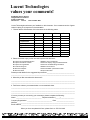
Lucent Technologies
values your comments!
AnyMedia® Access System
Integrated Access Terminal
Feature Supplement
Lucent Technologies welcomes your feedback on this document. Your comments can be of great
value in helping us to improve our documentation.
Please rate the effectiveness of this document in the following areas:
Excellent
Good
Fair
Poor
Ease of Use
Clarity
Completeness
Accuracy
Organization
Appearance
Examples
Illustration
Overall Satisfaction
Please check the ways you feel we could improve this document:
7 Improve the overview/introduction
7 Improve the table of contents
7 Improve the organization
7 Include more figures
7 Add more examples
7 Add more detail
7 Make it more concise/brief
7 Add more step-by-step procedures/tutorials
7 Add more troubleshooting information
7 Make it less technical
7 Add more/better quick reference aids
7 Improve the index
Please provide details for the suggested improvement._________________________________
What did you like most about this document?
Feel free to write any comments below or on an attached sheet.
If we may contact you concerning your comments, please complete the following:
Name: _______________________________ Telephone Number: (_____)_________________
Company/Organization: ______________________________ Date: _____________________
Address:______________________________________________________________________
Email Address:_________________________________________________________________
When you have completed this form, please fax it to: 973-581-6646.
363-211-127
Table of Contents
• Overview
xv
• Conventions Used in this Document
xviii
• Related Documentation
xx
• How to Order this Document
xxii
• How to Comment on this Document
xxiii
• Overview
2-1
• Applications
2-2
• Services
2-4
!
• Overview
3-1
• Configuration Options
3-2
• Central Office Bay Arrangements
3-4
• Remote Terminal Bay Configurations
3-7
• Additional Equipment Cabling
3-8
• Single System Arrangements
3-12
"
• Overview
4-1
• AnyMedia FAST Shelf Description
4-2
• Circuit Pack Common Functions and Characteristics
4-5
• AnyMedia Access System Apparatus Codes
4-6
• Circuit Pack—IODS1 FAC100
4-7
• Circuit Packs—COMDAC COM101, COMDAC COM102
4-8
• Circuit Packs—CTU DTP101, CTU DTP102, CTU DTP103
4-9
• Circuit Pack—IATS2 LPS100
4-10
• Circuit Pack—IATS4 LPS104
4-15
AnyMedia IAT Feature Supplement, Issue 5
October 2002
vii
363-211-127
Table of Contents
• Circuit Pack—IATS5 LPS105
#
4-20
$%&
• Overview
5-1
• OAM&P Interface
5-2
• Configuration Management
5-3
• Configuration Management—Memory Administration
5-4
• Configuration Management—Software Management
5-5
• Configuration Management—Service Activation
5-6
• Configuration Management—Provisioning
5-7
• Configuration Management—Slot Provisioning
5-8
• Configuration Management—Logical Subshelf Provisioning
5-9
• Configuration Management—Line Termination Provisioning
5-10
• Configuration Management—T0 Provisioning
5-14
• Configuration Management—DS1 IAT Server Port Provisioning
5-17
• Configuration Management—HDSL2 IAT Server Port Provisioning
5-19
• Configuration Management—VFDE/ClearReach Feature
5-21
• Configuration Management—Inventory Management
5-22
• Configuration Management—Synchronization Provisioning
5-24
• Configuration Management—Facility Data Link
5-25
• Configuration Management—Maintenance
5-26
• Performance Management
5-27
'
!
(
!
!
• Overview
6-1
• System Capacity
6-2
• Growth Scenarios
6-5
• Engineering Combinations of GR-303 and INA Configurations
for IAT-Only Systems
6-7
• Default System Provisioning Parameters
6-9
• Traffic and DS1 Engineering
6-16
• IATS4 Server HDSL2 Cable Distance Design
6-27
• HDSL2 IATS4 Server to IAT with DSX-1 Interface Application
6-28
• Management Interface Requirements
6-30
• Product Reliability
6-31
• Engineering Work Order for Traditional DLC Services
6-32
• Ordering
6-39
viii
October 2002
AnyMedia IAT Feature Supplement, Issue 5
363-211-127
Table of Contents
)
• Overview
*
7-1
+
• Overview
8-1
• Terminal Features
8-2
• Terminal Benefits
8-15
,
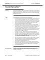
• Overview
9-1
• Basic ConnectReach Terminal and ConnectReach 200 Applications
9-2
• Metallic VF Lines Only Base System
9-5
• Metallic VF Lines and Data Base System
9-7
• Metallic VF Lines, Data, and Secondary T1/DSX-1 Application for
ConnectReach Terminal Only
9-10
• Metallic VF Lines, Data, and LCR Feature Application for
ConnectReach Terminal Only
9-12
• Metallic VF Lines, Data, Secondary
T1/DSX-1, and LCR Feature Application for
ConnectReach Terminal only
9-14
• Metallic VF Lines, Data, and BOX Feature Application for
ConnectReach Terminal Only
9-16
• Networking Applications
9-18
• ConnectReach Terminal and ConnectReach 200 Services
9-21
-
• Overview
10-1
• ConnectReach Terminal Description
10-2
• ConnectReach 200 Description
10-10
$%&
• Overview
11-1
• Configuration Management—Provisioning
11-2
• Configuration Management—Preconfiguration Information
11-4
AnyMedia IAT Feature Supplement, Issue 5
October 2002
ix
363-211-127
Table of Contents
.
/
0
x
October 2002
AnyMedia IAT Feature Supplement, Issue 5
363-211-127
List of Figures
.!
3
AnyMedia !
"#
!
"
#
'
3
$% &FAST#!
' (#)*
+
3
!#*FAST#!
' ,
3
AnyMedia' FAST#!
3
!!-. #FAST#!
!!'
/0%%(#1
3
233!!-.
3
233%!
3
+23!!-.
4
3
,23%!
5
3
4+23+!!-.
3
5+23+%!
$%&
3
+21.
)32$66
+
3
+212 3$678
+,
!
(
!
!
3
,2#'!'
FAST#!
9
,
3
,AnyMedia' (#*:;)
;
,4
3
)
,9.1(#.<
%%!,=
3
4 !#
AnyMedia IAT Feature Supplement, Issue 5
4
October 2002
xi
363-211-127
List of Figures
3
*
,
-
xii
4
33#
4
+
3
5(#!%#1
5
3
5>??1)
5
3
5*:
(#;.!.
5,
3
5LCR@;2-%
25=
3
5+LCR@!(#
3
5,@.!'(#.
5
53
3
=*!!;$!''
=+
3
=*!!;.'
=4
3
=*!!;A.A'B.<
%%!
=3
3
=*!!;A.A LCR%%!
=
3
=+*!!;A.A'B.<A
LCR%%!
#ConnectReach !
=
3
=,*!!;A.ABOX %%!
#
ConnectReach !
=,
3
=4?(-8'
==
3
=5AnyMedia' 9
!
33##$%!*!%!:
=3
3
3ConnectReach !2#'!. 3
3
3ConnectReach !!-.
3,
3
3ConnectReach !%!
34
3
3ConnectReach 208/216 !2#'!. 33
3
3+
!2#'!. 3
3
3,ConnectReach 200 !!-.
3
3
34
35
,%!
3+
3
35
%!
3+
October 2002
AnyMedia IAT Feature Supplement, Issue 5
363-211-127
List of Tables
.
3
"
'
6!9(21)0 #
ConnectReach ! ConnectReach 200
3
6!$11(
%%6'#@.23A.23A
.232-=
3
6!233%!/.
3
6!23%!/.
=
3
6!+23+%!/.
!
(
!
!
3
6!,! 1'.
!
,
3
6!,/1 !! .
!
,+
3
6!,.3%'C/!B %D
,3
AnyMedia IAT Feature Supplement, Issue 5
2-5
October 2002
xiii
363-211-127
List of Tables
xiv
October 2002
AnyMedia IAT Feature Supplement, Issue 5
About this Document
0
Overview
0
Purpose
0
This Feature Supplement—Integrated Access Terminal (hereinafter referred to as
the Integrated Access Terminal feature supplement) provides the following
information for support of Lucent Technologies AnyMedia® Access System
integrated access terminal (IAT) feature:
• An overview of the IAT feature
• Specific information about the features, benefits, applications, and
operation of supported AnyMedia Access System IATs
• Configuration and engineering information for planning purposes.
Intended audience
This document provides the information necessary to plan and engineer
equipment for AnyMedia Access System and its supported IATs and is intended
for the following users:
• Network planners
• Engineers.
Issue
This is Issue 5 of the AnyMedia® Access System (24 channel), Feature
Supplement—Integrated Access Terminal.
Reason for reissue
This feature supplement is being reissued to provide information about the
following:
• Describe the ConnectReach 200 Series (referred to as ConnectReach 200)
as an IAT supported by the AnyMedia Access System.
AnyMedia IAT Feature Supplement, Issue 5
October 2002
xv
363-211-127
About this Document
Overview
• The ConnectReach Plus Terminal is no longer supported.
• SOCKS is no longer supported in the ConnectReach Terminal.
• IPX functionality is no longer supported in the ConnectReach Terminal.
• To make other minor revisions, clarifications, and updates throughout the
material.
Content
This document contains the following information:
• An overview of the IAT feature
• A description of the IAT feature and its components
• Applications, services, and interfaces of the IATs
• Operations for the IAT feature
• Planning and engineering information
• Table of contents, acronym list, glossary, and index for the document, which
help readers find desired information quickly and easily
• A comment form so readers can give feedback to improve the next version
of the document.
For ordering information, see the AnyMedia® Access System, Ordering Guide,
code 363-211-125.
Document
organization
This document includes the following chapters, which provide details of the
AnyMedia Access System IAT feature:
• About this Document
Defines the purpose of the document and the intended audience. Also
includes topics about the conventions used in the document, related
documentation, how to order documents, and how to comment on this
document.
Part I, AnyMedia Access System IAT Feature
Chapters 1 through 6 describe the IAT feature generically.
• Chapter 1, Introduction
Describes the features, benefits, applications, and services of the
AnyMedia Access System when it is configured as an IAT host.
• Chapter 2, IAT Feature Applications and Services
Describes the applications and services provided when the AnyMedia
Access System is configured as an IAT host.
• Chapter 3, System Configurations
Describes the AnyMedia Access System feature configuration options in
support of IAT services.
xvi
October 2002
AnyMedia IAT Feature Supplement, Issue 5
363-211-127
About this Document
Overview
• Chapter 4, Product Description
Provides information about the AnyMedia FAST™ shelf and the common
system circuit packs and describes the IAT Servers.
• Chapter 5, OAM&P for IAT Services
Describes the OAM&P operations of the AnyMedia Access System for IAT
services.
• Chapter 6, System Planning and Engineering for IAT Services
Describes the engineering information required to incorporate the IAT
feature into the AnyMedia Access System and telecommunications
network, which includes capacities, traffic engineering, and default system
provisioning parameters.
Part II, ConnectReach Terminal and ConnectReach 200 Series
Chapters 7 through 11 describe the ConnectReach™ Terminal and
ConnectReach™ 200 Series, two IATs supported by the AnyMedia Access
System.
• Chapter 7, Introduction
Summarizes the features, benefits, applications, and services of the
ConnectReach Terminal and ConnectReach 200 Series.
• Chapter 8, Features and Benefits
Describes the features and benefits of the ConnectReach Terminal and
ConnectReach 200 Series.
• Chapter 9, Applications and Services
Describes the basic ConnectReach and ConnectReach 200 Series
applications supported by Lucent Technologies and the services provided
by the ConnectReach Terminal and ConnectReach 200 Series.
• Chapter 10, Product Description
Provides detailed descriptions of the ConnectReach Terminal and
ConnectReach 200 Series.
• Chapter 11, OAM&P
Describes the ConnectReach Terminal and ConnectReach 200 Series
operation interfaces. Preconfiguration and provisioning information also is
described.
• List of Acronyms
Lists the acronyms used to replace the longer expressions the acronyms
represent.
• Glossary
Defines terms that are used in this document.
• Index
Lists in alphabetical order the specific subject information in the document.
AnyMedia IAT Feature Supplement, Issue 5
October 2002
xvii
363-211-127
About this Document
Conventions Used in this Document
Conventions Used in this Document
Terms used
0
The following are terms used in the IAT feature supplement that may have a
different meaning than the general or common use of the term.
• In the AnyMedia Access System, the term access means that the system
provides the primary service interface for the customer to enter the network.
• Traditional digital loop carrier (DLC) services refer to traditional telephony
services, which include plain old telephone service (POTS), coin, integrated
services digital network (ISDN), and two-wire locally switched, nonswitched,
and nonlocally switched services.
• Special services refer to two-wire and four-wire nonswitched and nonlocally
switched special services.
• Voice frequency (VF) is used generically to define POTS, two-wire and fourwire special services, ISDN, digital data services (DDS), enhanced
business services (EBS) P-Phone, and digital bypass pair and DC alarm
circuits to an existing DLC system. VF growth is used generically to define
the growth or addition of these services.
• Digital data services (DDS) refer to 64 kbps clear channel digital service
provided between the customer and the central office (CO).
• IAT features apply to all integrated access devices (IADs) that are
supported by the AnyMedia Access System, including the ConnectReach
Terminal and ConnectReach 200 Series.
Acronyms and
abbreviations
In the first three chapters, acronyms are spelled out in lower case letters the first
time they are used. Acronyms are also expanded if the section topic is specifically
about the acronym. All acronyms may be found in the Acronym list located in the
back of the document.
Initial caps are used only when the acronym represents a system (e.g., Switched
Access Remote Test [SARTS]) or when used in a heading. If the acronym is a
trademark, it will not be spelled out.
Commands
AnyMedia Access System TL1 command names are displayed in constantwidth font and are uppercase (e.g., RTRV-COND).
Trademarks
The trademarks used in this document are identified the first time on the
trademark page. Trademarks of Lucent Technologies and other companies are in
italics, and the trademarks modify a noun (e.g., the system name contains a
xviii
October 2002
AnyMedia IAT Feature Supplement, Issue 5
363-211-127
About this Document
Conventions Used in this Document
registered trademark, AnyMedia Access System). A trademark is not treated as
an acronym (it is not spelled out or expanded).
Lucent Technologies trademarks
0
Lucent Technologies trademarks are identified with the registered mark ( ® ) or
trademark ( ™ ) symbol the first time the trademarks are used in the text.
Trademarks of other companies
0
The trademarks of other companies are identified the first time on the trademark
page. Trademark references from there on are in italics.
AnyMedia IAT Feature Supplement, Issue 5
October 2002
xix
363-211-127
About this Document
Related Documentation
Related Documentation
Document list,
packaging, and
formats
0
The following documentation is available for the AnyMedia Access System:
Available on the Web
0
• AnyMedia Access System Documents
— 363-211-125, AnyMedia® Access System, Ordering Guide
http://www.lucent8.com/library/AnyMediaOrderingGuide.pdf
— Other AnyMedia Access System documents, including System Release
Descriptions (SRDs) and the Navis™ AnyMedia Element Management
System (EMS), can be found by going to http://www.lucent8.com,
selecting “Documents”, then selecting “Product Line: AnyMedia” (under
“Enter 1 or more search items below”) and “Search Now”.
An SRD is issued per release and describes the functionality of the
system at the time of release.
Available on CD-ROM
0
363-211-103, AnyMedia® Access System, Documentation, which is a
CD-ROM that contains the following documents in various formats:
• AnyMedia Access System Documents
— 363-211-254, AnyMedia® Access System, Product Data Sheets (in PDF
format)
— 363-211-101, AnyMedia® Access System, Applications, Planning, and
Ordering Guide (APOG) (in PDF format)
— 363-211-106, AnyMedia® Access System, Feature Supplement—MDS2
Shelf Configurations (in PDF format)
— 363-211-127, AnyMedia® Access System, Feature Supplement—
Integrated Access Terminal (in PDF format)
— 363-211-128, AnyMedia® Access System, Feature Supplement—
Central Office Terminal (in PDF format)
— 363-211-125, AnyMedia® Access System, Ordering Guide (in PDF
format)
— 363-211-102, AnyMedia® Access System, Installation Manual (in PDF
format)
— AnyMedia® Access System, Commands and Procedures (363-211-100,
in HTML format, also includes PDFs of selected procedures)
— 363-211-129, AnyMedia® Access System, ConnectReach™ Terminal
User’s Guide (in PDF format)
— 363-211-212, AnyMedia® Access System, ConnectReach™ Series 200
User’s Guide (in PDF format)
xx
October 2002
AnyMedia IAT Feature Supplement, Issue 5
363-211-127
About this Document
Related Documentation
— 363-211-520, AnyMedia® Access System (24 Channel) Optical Network
Unit Installation Manual for Outdoor Applications (in PDF format)
— 363-211-521, AnyMedia® Access System (24 Channel) Optical Network
Unit Installation Manual for Indoor Applications (in PDF format)
• SLC Documents
— SLC Series 5 Carrier System J1C182BC-1 Remote Terminal Ring Shelf,
User Manual (in PDF format)
127(
An Adobe Acrobat Reader is provided to view all PDF files.
For documents in HTML format, users need and must supply their own Web
browser to view them. The documentation has been verified using the
following Web browsers: Netscape Navigator 4.0 and Internet Explorer 5.0
or later.
The AnyMedia Access System Management Interface, which includes the
graphical system interface (GSI) and the Network Maintenance Manager, is
available on CD-ROM.
AnyMedia IAT Feature Supplement, Issue 5
October 2002
xxi
363-211-127
About this Document
How to Order this Document
How to Order this Document
0
Ordering number
The ordering number for the AnyMedia® Access System, Feature Supplement—
Integrated Access Terminal is 363-211-127.
Order procedure
To order additional hard copies of this document and/or to request placement on
the standing order list, send or call in an order as follows:
Customer
Mail Order
Telephone Order
(Monday through Friday)
Commercial
Customers∗
Lucent Technologies
Customer Information Center
Attention: Order Entry Center
2855 N. Franklin Road
P.O. Box 19901
Indianapolis, IN 46219
- Within USA:1-888-LUCENT8
7:30 a.m. to 6:30 p.m. EST
- FAX from USA and Canada:
1-800-566-9568
- FAX Worldwide:
1-317-322-6699
Local
exchange
carriers
Process through your Company Documentation Coordinator
∗ For commercial customers, a check, money order, purchase order number, or
charge card number is required with all orders. Make checks payable to Lucent
Technologies. Lucent Technologies entities should use Form IND 1-80.80 FA,
available through the Customer Information Center.
One-time orders
One-time orders include the contents for the current document issue in effect at
the time of order.
Standing orders
You may request placement on the standing order list for all later reissues of any
document. The standing order list for each document provides automatic
distribution for all reissues of the document.
Local exchange
carrier orders
Local exchange carrier customers should process documentation orders or
standing order requests through their Company Documentation Coordinator.
xxii
October 2002
AnyMedia IAT Feature Supplement, Issue 5
363-211-127
About this Document
How to Comment on this Document
How to Comment on this Document
Document comment
procedure
Please fax your comments and suggestions concerning this document to 973581-6646.
AnyMedia IAT Feature Supplement, Issue 5
0
October 2002
xxiii
How to Comment on this Document
xxiv
October 2002
363-211-127
About this Document
AnyMedia IAT Feature Supplement, Issue 5
Part I: AnyMedia Access System IAT Feature
Introduction
1
1
Overview
This document includes the applications and engineering planning
information for the AnyMedia Access System when supporting the integrated
access terminal (IAT) feature. It also contains generic information to support
IAT products using a standard signalling interface or a feature enhanced
interface that supports specific IATs.
Features and value
The AnyMedia Access System, when supporting the IAT feature, enables
telecommunications suppliers to offer flexible services to small- and mediumsized businesses and yet retain the fundamental values of the AnyMedia
Access System.
The set of services that can be deployed at an IAT are voice, digital data,
private branch exchange (PBX) functions, router capability, and firewall.
The AnyMedia Access System supports up to 80 server ports from each
FAST shelf. Each port provides either a high bit rate digital subscriber
line-second generation (HDSL2) or a digital signal, level 1 (DS1) interface that
can be delivered to end customers over a large variety of facilities. The end
customer is served by an IAT with either a D4-compatible interface or a
feature enhanced interface that supports specific IATs. The IAT feature of the
AnyMedia Access System can be customized to the service and cost needs
of the end customer.
When the AnyMedia Access System is configured to support IAT hosting, the
following values are delivered:
• GR-303 and integrated network access (INA) interfaces to the network.
This allows the AnyMedia Access System to collect the various services
from a large collection of IATs and groom and concentrate them for
maximum efficiency for the service provider.
AnyMedia IAT Feature Supplement, Issue 5
October 2002
1-1
363-211-127
• Concentration over large line sizes. The AnyMedia Access System can
support up to 1920 channels between the AnyMedia Access System and
the IATs and can deliver them to a GR-303 local digital switch (LDS) with
fewer LDS interfaces. When the AnyMedia Access System is serving 1920
lines on IATs and 20 feeders are delivered to a GR-303 LDS, the
concentration ratio is 4:1. The minimum concentration ratio with a fully
loaded system is 1.6:1 (using 2-port IAT Servers and supporting 768 lines
on IATs).
• An HDSL2 or DS1 interface that allows the service provider to choose the
most efficient transport to the IAT. Choices include T1 carrier, HDSL2,
synchronous optical network (SONET) facilities, and wireless.
• Efficient use of outside plant facilities by using DS1 transport to combine the
end customer’s service needs. Other applications may require the use of
multiple, partially filled facilities at a much higher cost.
• A mix of IAT Servers, MDS2 servers, and other APs.
The service provider can select from a wide variety of IATs on the market today
with the choice based on end customer service needs and cost. The feature set of
the selected IAT is based on the IAT manufacturers’ value added designs.
Two basic IAT interfaces are available on the AnyMedia Access System:
• D4 (PUB 43801)—A large variety of premises equipment products are
available that will operate with this interface.
• Feature enhanced—This interface can be used with two Lucent products,
the ConnectReach Terminal and ConnectReach 200. These products have
enhanced features for PBX and Internet services and also can be remotely
managed from an AnyMedia Access System terminal.
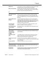
Applications and
services
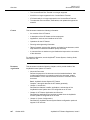
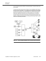
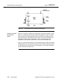
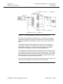
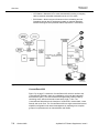
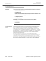
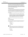
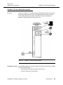
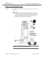
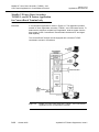
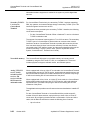
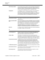
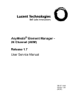
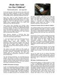
Figure 1-1 on page 1-3 shows a typical AnyMedia Access System IAT feature
application. At the IAT end customer location, an IAT specific to the end
customer’s needs is chosen. The figure shows an IAT that supports plain old
telephone service (POTS) (voice) lines, analog or digital trunks to a PBX, and high
speed Internet access. Some IATs can provide PBX functionality as well as other
services.
Figure 1-1 also shows the facility from the AnyMedia Access System to the IAT
location. This facility can be any medium that supports DS1 capabilities, such as
T1 carrier, HDSL2, SONET, or DS1 capable radio. Each AnyMedia Access
System can support up to 80 IATs in up to 80 different locations.
The AnyMedia Access System with the IAT feature can provide concentrated
GR-303 services to an LDS. In addition, direct inward dialing (DID) trunks, foreign
exchange (FX) lines, and other special services from the IAT can be routed
through the AnyMedia Access System’s INA interfaces. This interface also can
1-2
October 2002
AnyMedia IAT Feature Supplement, Issue 5
363-211-127
Introduction
support digital data services (DDS) to corporate networks or Internet access to the
end customer.
The service provider has the choice of location for the AnyMedia Access System
providing the service capability. The AnyMedia Access System may be collocated
with the service provider’s LDS. In this application, the AnyMedia Access System
provides local concentration and INA fill benefits. The service provider also can
deploy the AnyMedia Access System in a remote building, hut, or controlled
environment vault (CEV) located according to standard outside plant planning
practices. Finally, the service provider, acting as a network service provider, could
install the AnyMedia Access System in an existing local exchange carrier’s central
office (CO) if unbundling rules permit.
Figure 1-1.
Basic AnyMedia Integrated Access Terminal Feature Architecture
AnyMedia IAT Feature Supplement, Issue 5
October 2002
1-3
363-211-127
1-4
October 2002
AnyMedia IAT Feature Supplement, Issue 5
IAT Feature Applications and
Services
2
Overview
2
2
This chapter discusses the applications and services provided by the AnyMedia
Access System IAT feature.
Page
Applications
2-2
Services
2-4
AnyMedia IAT Feature Supplement, Issue 5
October 2002
2-1
,4
%%!1
%%!
Applications
Overview
2
The AnyMedia Access System, when used as a host for IAT services, provides
most of the features of the AnyMedia Access System. Listed below are the key
values of the AnyMedia Access System equipped with the IAT feature:
• COMDAC, CTU, and IODS1 common packs are used with the same
functionality as in a voice AnyMedia Access System.
• Integrated GR-303 LDS and INA interfaces are supported (no
TR-NWT-000008* for IAT lines).
• Simplified operations, administration, maintenance, and provisioning
(OAM&P) operations are provided via the graphical system interface (GSI)
of the AnyMedia Management Interface.
• All FAST shelf list numbers support the IAT feature.
• In the FAST shelf, IAT Servers can be mixed with all other application packs
(APs) including xDSL packs, an AFM, and the MDSU.
• Sixteen IAT Servers, providing up to 80 ports, may be installed in one FAST
shelf.
• IAT Server cables (Y-cables) are needed to connect DS1 ports from the IAT
Server to a DSX-1 cross connect.
• Standard voice frequency (VF) cables are used for IAT Servers with HDSL2
interface.
• If the FAST shelf is equipped exclusively with DS1 IAT Servers, no fans are
needed; baffles are sufficient. Fans are required when HDSL2 IAT Servers
are used.
• No ringing generator or ringing power cables are required for IAT-only
systems. These are required if other APs are mixed with IAT Servers.
• An AnyMedia Access System fully equipped with IATS2 Servers can
support 32 IATs. When fully equipped with IATS5 Servers, the AnyMedia
Access System can support 80 IATs. When it is fully equipped with IATS4
Servers, the AnyMedia Access System can support 64 IATs.
• When working with the ConnectReach Terminal and the ConnectReach200,
the ClearReach™ feature is also available. This feature requires voice
frequency data enhancement (VFDE) in the AnyMedia FAST shelf.
*
2-2
TR-NWT-000008, “Digital Interface Between the SLC-96 Digital Loop Carrier System and a Local Digital Switch,”
Issue 2 (Telcordia Technologies, Inc., August, 1987) plus Revision 1, September 1993
October 2002
AnyMedia IAT Feature Supplement, Issue 5
,4
%%!1
%%!
• For specially designed IAT products such as the ConnectReach Terminal
and ConnectReach 200, a remote operations facility data link feature of the
AnyMedia Access System allows remote provisioning of these IATs (see
Chapter 5, OAM&P for IAT Services for more detail).
AnyMedia IAT Feature Supplement, Issue 5
October 2002
2-3
,4
%%!1
1
Services
Overview
2
The AnyMedia Access System provides a variety of locally switched, nonlocally
switched, and nonswitched services. Services are described separately for the
ConnectReach Terminal and ConnectReach 200 and the standard D4 interface.
The type of IAT determines the services available via the AnyMedia Access
System. Two types of IATs are supported as logical subshelves of the AnyMedia
Access System—IAT01 and IAT02. The subshelf type IAT01 refers to both the
ConnectReach Terminal and ConnectReach 200. The subshelf type IAT02 refers
to the industry standard (nonproprietary) D4 type of IAT.
ConnectReach
Terminal and
ConnectReach 200
(IAT01) services
Services available for the IAT01 include the following:
• Two-wire POTS
• Two-wire loop start (2LS) with and without line-side answer supervision *
• Two-wire ground start (2GS) with and without line-side answer supervision*
• Direct inward dialing (DID)—dial pulse terminating (DPT) (ConnectReach
Terminal only)
• Foreign exchange station (FXS) lines and trunks (ConnectReach Terminal
only)
• 64 kbps clear channel data for Internet access
• Multiple channels of 64 kbps data (Nx64)
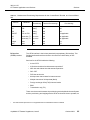
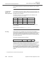
The ConnectReach Terminal and ConnectReach 200, referred to as IAT01 by the
AnyMedia Access System, require matching provisioning and equipage to provide
these services. The AnyMedia Access System and the IAT01 communicate via a
data link on the DS1 or HDSL2 line between the IAT Server and the IAT01
terminal to compare the provisioning and equipage. If provisioning at the
AnyMedia Access System matches the provisioning and equipage at the
ConnectReach Terminal or ConnectReach 200, then these services will operate. If
there is a mismatch, those lines that have a mismatch will be out of service.
These IAT01 services require the following hardware and provisioning in the
ConnectReach Terminal and ConnectReach 200:
*
2-4
Line-side answer supervision is not supported when the ClearReach feature is enabled.
October 2002
AnyMedia IAT Feature Supplement, Issue 5
,4
%%!1
1
Table 2-1. Hardware and Provisioning Requirements for the ConnectReach Terminal and ConnectReach
200
Service
Hardware
DS0
Provisioning
ConnectReach
Terminal Provisioninga
ConnectReach 200
Provisioninga
POTS
FXS
analog
440
440
2LS
FXS
analog
440
440
2GS
FXS
analog
440
440
DID/DPT
FXO or FXS
analog
456
Not applicable
FXS
Secondary T1 sec-voice
443
Not applicable
2LS
Secondary T1 sec-voice
400
Not applicable
64 kbps
Data
data
452
452
Nx64
Data
data
452
452
!
"%# @E
D4 interface
(IAT02) services
The IAT02 interface is the industry standard (nonproprietary) D4 interface. This
flexible interface allows the end user to choose from a wide variety of IATs
available.
Services for the IAT02 include the following:
• 2-wire POTS
• 2LS with and without line-side answer supervision *
• 2GS with and without line-side answer supervision*
• DID—DPT
• FXS lines and trunks
• 64 kbps clear channel data for Internet access
• Multiple channels of 64 kbps data (Nx64)
• Foreign exchange office (FXO) lines and trunks
• E&M
• Transmission only (TO).
There must be a match between the provisioning at the AnyMedia Access System
and the provisioning and equipage at the IAT02 for these services to operate, but
*
Line-side answer supervision is not supported when the ClearReach feature is enabled.
AnyMedia IAT Feature Supplement, Issue 5
October 2002
2-5
1
,4
%%!1
the AnyMedia Access System does not verify the IAT02 provisioning and
equipage and declare mismatches, as in the IAT01 case.
2-6
October 2002
AnyMedia IAT Feature Supplement, Issue 5
System Configurations
3
Overview
3
3
This chapter details the AnyMedia Access System configuration options in
support of IAT services only. Refer to the AnyMedia® Access System,
Applications, Planning, and Ordering Guide for details on configuration options
when AnyMedia Access Systems with APs are used or are mixed with AnyMedia
Access Systems with IAT services.
Configuration Options
3-2
Central Office Bay Arrangements
3-4
Remote Terminal Bay Configurations
3-7
Additional Equipment Cabling
3-8
Single System Arrangements
3-12
%%! A+
$633
,4
' $%
Configuration Options
Overview
3
Configuration options of the AnyMedia Access System in support of IAT services
include the following:
• Central office (CO) bay arrangement
• Remote terminal (RT) bay arrangement
• Single system arrangements (single FAST shelf).
This section discusses these configuration options and how they can be used to
support VF growth and IAT service applications.
CO bay
arrangement
The CO bay arrangement of the AnyMedia Access System is used for
applications that will require the AnyMedia Access System RT equipment placed
in bays in a CO environment. This arrangement provides a solution for
competitive access applications where a network service provider establishes a
switching center at a convenient location and transports DS1-based facilities from
the network service provider’s digital switch to the AnyMedia Access System RT.
The IAT Servers in the AnyMedia Access System RT are connected to the IATs,
such as the AnyMedia Access System ConnectReach Terminal and
ConnectReach 200, via DS1 server cables.
Typical installations in COs require installation of equipment in bays that have
access from both the front and rear of the bay. Server connections are through
DSX cross connects to the required server transport facilities such as T1 carrier,
HDSL2, SONET transport, or DS1 capable radio. Specific bay and shelf
arrangements for the CO are described in Central Office Bay Arrangements on
page 3-4.
Both flush mount and RT-bay type arrangements are available.
RT bay
arrangement
The RT bay arrangement of the AnyMedia Access System is used for applications
that will require the AnyMedia Access System RT equipment to be placed in bays
in an RT environment. The RT bay arrangement provides a solution for supporting
IAT Servers in a local exchange carrier environment. The FAST shelf is placed in
a bay in an indoor environment such as a hut, a CEV, or in a subscriber’s
equipment room.
These applications may mount the bays against walls or in back-to-back
arrangements to conserve space with front-only access of the bays. Server
connections are through cross connects to the required server transport facilities
$633
%%! A+
,4
' $%
such as T1 carrier, HDSL2, SONET transport, or DS1 capable radio. Specific bay
and shelf arrangements for the RT are described in Remote Terminal Bay
Configurations on page 3-7.
3
Single shelf
arrangements
Single shelf arrangements are used for applications needing less than a complete
bay of equipment, such as small applications and slow growth applications. Single
shelf arrangements are described in Single System Arrangements on page 3-12.
%%! A+
$633
,4
' !$
' Central Office Bay Arrangements
Overview
3
The AnyMedia Access System can be mounted in a bay with front and rear
access, which typically is used in a CO environment. The system may be installed
in a CO bay line up in a flush mount arrangement.
For the CO environment, the AnyMedia Access System can be mounted in a
seismic 7-foot RT bay (ED8C800 type). The bays are 26 inches wide, accept
AnyMedia Access System shelves with 23-inch mounting centers, and up to four
FAST shelves can be installed in a single bay.
127(
All equipment described in this section are specified in Appendix C, Floor
Plan Data Sheets, of the AnyMedia® Access System, Applications,
Planning, and Ordering Guide. These are separately orderable items listed
in the AnyMedia® Access System, Ordering Guide.
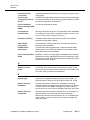
Optimized FAST
shelf bay
arrangement
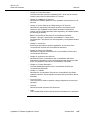
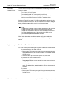
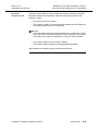
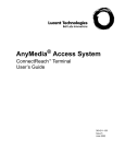
The optimized FAST shelf bay arrangement for all DS1 IATS2 and IATS5Servers
is equipped with four FAST shelves and convection cooling equipment. Figure 3-1
on page 3-5 shows the natural convection optimized FAST shelf bay
arrangements and the shelf mounting arrangement from the front of the bay.
If FAST shelves filled exclusively with DS1 IAT Servers are mixed with FAST
shelves with APs, the FAST shelves with DS1 IAT Servers must use baffles above
the shelf. The FAST shelves with HDSL2 IATS4 Servers and/or APs must have
either fans or baffles above, based on design criteria in the AnyMedia® Access
System, Applications, Planning, and Ordering Guide.
$633
%%! A+
,4
' !$
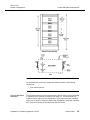
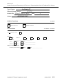
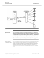
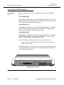
' Figure 3-1.
Optimized FAST Shelf Bay Arrangements with RT Mount
An optimized FAST shelf bay arrangement offering consists of the following
components:
• Four shelves per bay.
Central office flush
mount bay
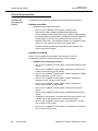
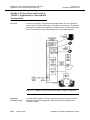
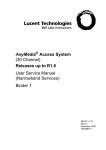
The CO flush mount bay can be used similarly to the RT mount CO bay described
in Optimized FAST shelf bay arrangement on page 3-4. The flush mount bay
would be used to align with other equipment in a CO aisle that is flush-mounted.
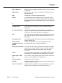
Figure 3-2 on page 3-6 shows the shelf-to-bay arrangement of the flush-mounted
bay. The flush mounting requires both front and rear access.
%%! A+
$633
!$
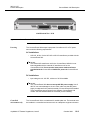
' Figure 3-2.
Natural convection
bay with heat
baffles
,4
' Flush-Mounted FAST Shelf Bay Arrangement
Figure 3-1 on page 3-5 shows a bay configuration for natural convection. A heat
baffle, which dissipates the thermal emissions generated by the shelf, is placed
above the shelf so the thermal emissions from the shelf do not affect any other
shelf’s performance. Heat baffles should be used in IAT Server applications, as
specified for the FAST shelf in Appendix C, Floor Plan Data Sheets, of the
AnyMedia® Access System, Applications, Planning, and Ordering Guide.
Figure 3-1 shows the heat baffles, which are approximately 3 inches high and are
installed above each shelf except the top shelf. A FAST shelf containing only DS1
IAT Servers does not require fans for heat dissipation. FAST shelves containing
HDSL2 IATS4 Servers require fans.
$633
%%! A+
,4
' ) !'
Remote Terminal Bay Configurations
Overview
3
The AnyMedia Access System can be placed in bays, huts, CEVs, subscriber
premises, or anywhere that traditional DLC is deployed. The bay arrangements
are the same as those used for the CO configuration except that typically the RT
bays are mounted against walls or in back-to-back arrangements to conserve
space. Typically, these installations have front-only access.
For the RT environment, the AnyMedia Access System is mounted in a seismic
7-foot RT bay (ED8C800 type). The bays are 26 inches wide, accept AnyMedia
Access System shelves with 23-inch mounting centers, and up to four FAST
shelves can be installed in a single bay.
127(
All equipment described in this section are specified in Appendix C, Floor
Plan Data Sheets, of the AnyMedia® Access System, Applications,
Planning, and Ordering Guide. These are separately orderable items listed
in the AnyMedia® Access System, Ordering Guide.
%%! A+
$633
,4
' !/0% 6!
Additional Equipment Cabling
Overview
3
The FAST shelf cabling required to support the DS1 IAT feature differs from the
AP application since the VF cables are replaced by DS1 server cables. Also, local
ringing is not required. Details of the cabling needs of the AnyMedia Access
System IAT feature are contained in this section.
HDSL2 IATS4 Servers require standard VF cables (see HDSL2 IAT Server
distribution cables on page 3-10).
FAST shelf cabling
locations
In CO applications, the FAST shelf is mounted into either a CO type or RT type
bay. With a flush mount shelf mounted in a CO type bay, the cable duct is in the
rear. In an RT type bay, the cable duct is in front. A cable trough is located at the
bottom front of the shelf. The DS1 server cables plug into the faceplate connector
of each IAT Server. Each DS1 cable from the IAT Server routes into the FAST
shelf cable trough, exits the side of the shelf and feeds into the associated bay
cable duct. DS1 cables from eight IAT Servers are routed out the right side of the
shelf, and the DS1 cables from the other eight IAT Servers are routed out the left
side of the shelf.
For flush mounting, input/output (I/O) cables from the backplane (including DS1)
feeders, local area network (LAN) interface, etc., are routed along the backplane
to the side of the shelf and up the bay between the shelves of adjacent bays.
These are not routed in the bay cable duct. For RT mounting applications, all
cables are routed in the bay cable duct.
Associated
equipment
Generally, the following equipment must be connected to the system to support its
complete operation. There may be alternatives to the identified equipment, and
specifically recommended equipment is identified as known or needed. In COs,
this equipment may be shared over many AnyMedia Access Systems or among
many different other equipment types not related to the AnyMedia Access System
access application. These components can be installed in the AnyMedia Access
System bays or may be placed in adjacent bays or remote locations in the office
or building.
• Power plant or power consumption needs
• Transport equipment and facilities
• DSX-1 cross-connect
Power plant or power consumption needs
3
The amount and type of power needed for the system bay and for associated
equipment are specified in the FAST Shelf Powering section of Chapter 10,
System Planning and Engineering for Traditional DLC Services, of the AnyMedia®
$633
%%! A+
,4
' !/0% 6!
Access System, Applications, Planning, and Ordering Guide and in Appendix C,
Floor Plan Data Sheets, of the Applications, Planning, and Ordering Guide. This
power plant could be unique to the application of the AnyMedia Access System or
shared with other office equipment.
Transport equipment and facilities
3
A choice of products can be offered including a fiber multiplexer like digital data
multiplexer (DDM)-2000, SLC®-2000 access resource manager (ARM) shelf, T1
carrier office repeater bays, or other DS1 level transport equipment. The FAST
shelf DS1 transport interface is based on the T1.102 standard so that a large
selection of transport systems are compatible with the AnyMedia Access System.
DSX-1 cross-connect
3
A FAST shelf connects to transport equipment at a DS1 level. Therefore, a DSX-1
cross connect panel must be available and placed at a location within equalization
range of both the transport system and the FAST shelf. This distance is wiregauge dependent, typically no more that 655 feet from each terminal for 22-gauge
wire. DSX-1 cross-connects are required for both AnyMedia Access System DS1
transport to the LDS and for the IAT Server DS1 transport.
Mixed shelf cabling
The engineer should carefully plan for the type of cabling required for the FAST
shelf based on service needs. The duct space and shelf trough cannot hold both
VF and DS1 IAT Server cables simultaneously. The recommendations below
assure that the FAST shelf usually is equipped to support VF AP services.
• If the forecast shows that the shelf will be used predominately for VF APs,
only VF cables need to be installed.
• If the forecast shows that the shelf will be used exclusively for DS1 IAT
Servers (IATS2 and IATS5), only DS1 IAT Server cables need to be
installed.
• If the shelf may need to support a mix of VF APs, HDSL2 IAT Servers
(IATS4), and DS1 IAT Servers, it is recommended that the shelf be
equipped initially with a full set of VF cables. This guarantees that VF
growth can be accommodated without having a major cable installation
activity. Procedures are available to remove VF cables from the shelf and
install DS1 IAT Server cable with a minimum of effort. The removed VF
cables can be stored in the duct or in the rack over the bay for possible
future use.
• The installation of a full set of DS1 IAT Server cables for the case
immediately above is not necessary since the installation of DS1 IAT Server
cables is simpler due to fewer pairs terminated and the smaller size of the
cables. In addition, the use of DS1 IAT Servers also requires adding other
equipment, such as transport equipment and DSX-1 cross-connects, which
results in a significant installation activity.
%%! A+
$633
,4
' !/0% 6!
• In large installations, it is also recommended that VF services be
segregated from DS1 IAT services so that whole shelves can be cabled for
each service type, as suggested in the first two bullet items above.
Cabling—detailed
description
Required cabling includes the following:
• DS1 cables for office facilities
• DS1 cables for server transport
• HDSL2 IAT Server distribution cables (standard VF cables)
• Power cables
• Operations connection cables
• Miscellaneous alarm cables
• CO output alarm cables.
DS1 cables (facility)
3
Each FAST shelf can terminate 20DS1 circuits from the transport facility on five
IODS1 packs. A sixth pack provides 1:5 protection of the five in-service IODS1
packs. The protection IODS1 pack has no DS1 cabling connections. Connection
to the transport facility, separating transmit and receive pairs, is required. These
cables terminate at the DSX-1 panel.
DS1 cables (server transport)
3
For IATS2 and IATS5 Servers, Y-cables connect to the faceplates of the servers
and pass through the cable trough to the sides of the bay. Different Y-cable types
are needed for each IAT Server type. The IATS2 Server supports two DS1
interfaces, and the IATS5 Server supports five DS1 interfaces. The Y-cables are
split into DS1 transmit and DS1 receive paths with connectors on the ends.
Additional cables connect to the ends of the Y-cable to be routed to a DSX-1
panel. The IATS2 Y-cable faceplate connector is a 15-pin D-sub, and the IATS5
Y-cable faceplate connector is a 25-pin D-sub.
HDSL2 IAT Server distribution cables
3
The IATS4 Server, which provides an HDSL2 interface, uses the same 32-port VF
cable used by POTS APs. This cable connects to the faceplate of the IATS4
Server via the same type of connector that is provided on all APs. The first four
pairs provide the HDSL2 interface. The remainder of the pairs are not active.
Power cables
3
Cables are provided for two –48V inputs and returns to the FAST shelf.
Appropriate grounding (single-point or mesh) is also specified for the bay.
$633
%%! A+
,4
' !/0% 6!
Operations connection cables
3
For IAT related services, the GSI or TL1SI terminal connects via a cable to an
EIA-232E/574 compatible connector on the faceplate of the craft test unit (CTU)
and to the com port on the personal computer (PC) or TL1SI terminal. A PC
equipped with an Ethernet LAN card also can be connected to the 10BaseT LAN
connection on the FAST shelf.
Miscellaneous alarm cables
3
Miscellaneous discrete input alarms require cables that come from a connector on
the backplane of the FAST shelf. For front-only access in RT applications, the
cables are accessed from a connection to a dangler cable. Two connectors (J111,
J111A) are used for miscellaneous alarm inputs, such as the cabinet door alarm.
These are connected to the CTU slot on the FAST shelf.
CO output alarm cables
3
Alarm signals output from an office alarms cable via a J110 dangler on the
backplane. Alarm signals from the connector are routed to the CTU slot on the
FAST shelf.
%%! A+
$633
,4
' !' Single System Arrangements
Overview
3
For applications that need less than a complete bay of equipment, such as those
listed below, the customer could consider a single FAST shelf:
• Small applications that require up to 80 IATs
• Slow growth applications.
Small applications
If the application requires up to 80 IATs, which is the capacity of a single FAST
shelf, the shelf could be mounted in available space in any available bay with the
same physical characteristics as the ED8C800-50 type bays described in Central
Office Bay Arrangements on page 3-4. A heat baffle is required above each FAST
shelf equipped exclusively with DS1 IATS2 and IATS5 Servers except when the
FAST shelf is mounted at the top of the bay.
Fans are required when a FAST shelf contains one or more HDSL2 IATS4
Servers.
Slow growth
applications
$633
If more than one shelf of equipment may be needed but growth is slow, it may be
preferable to install a single FAST shelf at a time. The first shelf should be
installed at the bottom of the bay using the same mounting holes as specified in
the AnyMedia® Access System, Installation Manual, Chapter 2 for a full bay of
equipment. The bay type should be the same as specified for the fully equipped
bay. Subsequent shelf additions are installed from the bottom up, using heat
baffles. Each shelf should be associated with a heat baffle mounted above it
except for a shelf at the top of the bay (see Figure 3-1 on page 3-5).
%%! A+
Product Description
4
Overview
4
4
This chapter provides information about the FAST shelf, the common system
circuit packs, and the IAT Server.
Page
AnyMedia FAST Shelf Description
4-2
Circuit Pack Common Functions and Characteristics
4-5
AnyMedia Access System Apparatus Codes
4-6
Circuit Pack—IODS1 FAC100
4-7
Circuit Packs—COMDAC COM101, COMDAC COM102
4-8
Circuit Packs—CTU DTP101, CTU DTP102, CTU DTP103
4-9
Circuit Pack—IATS2 LPS100
4-10
Circuit Pack—IATS4 LPS104
4-15
Circuit Pack—IATS5 LPS105
4-20
AnyMedia IAT Feature Supplement, Issue 5
October 2002
4-1
,4
2.%
AnyMedia FAST#!
.%
AnyMedia FAST Shelf Description
Overview
4
The FAST shelf is the main shelf in the AnyMedia Access System. When it is
configured as an IAT-only host, the FAST shelf supports the following:
• Up to 6 IODS1s
• Up to 2 COMDACs
• 1 CTU
• 16 IAT Servers.
There are six possible FAST shelf choices based on the applications described in
the AnyMedia® Access System, Applications, Planning, and Ordering Guide. The
choices depend on whether the shelf is front and rear access or front-only access
and on the type of powering.
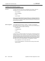
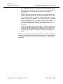
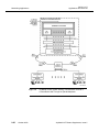
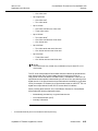
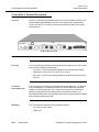
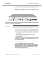
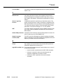
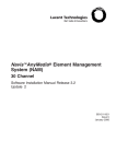
Shelf arrangement
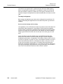
The AnyMedia FAST shelf shown in Figure 4-1 on page 4-3 is arranged to
accommodate 6 small and 19 large circuit packs, all on 25 mm horizontal spacing.
From left to right, the shelf contains the following:
• 6 IODS1 packs
• 2 COMDAC packs
• 1 CTU
• 16 IAT Servers.
A cable trough is located at the bottom front of the shelf. The cables plug into the
faceplate connectors of the IAT Servers. These cables are routed vertically down
into the cable trough and are routed vertically down to the cable trough. Then the
cables are routed horizontally through the trough to either side of the shelf; half of
the cables exit the trough on the right side, and half on the left side. After exiting
the trough, the route of the cables depends on the application, as follows:
• RT bay applications—Into the bay cable ducts
• Flush-mounted applications—Under the shelf for routing in the bay cable
ducts in the rear.
4-2
October 2002
AnyMedia IAT Feature Supplement, Issue 5
,4
2.%
AnyMedia FAST#!
.%
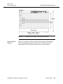
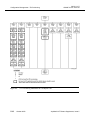
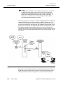
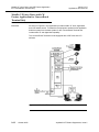
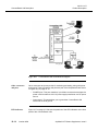
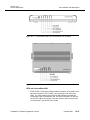
Figure 4-1.
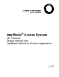
Functional block
diagram
AnyMedia Access System FAST Shelf Arrangement
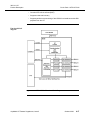
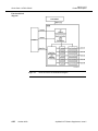
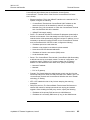
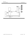
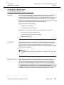
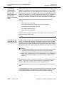
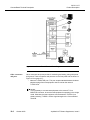
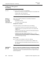
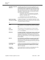
Figure 4-2 on page 4-4 provides a functional block diagram of the AnyMedia
FAST shelf equipped exclusively with IAT Servers. This figure shows the
relationships of the circuit packs described in the rest of this chapter.
AnyMedia IAT Feature Supplement, Issue 5
October 2002
4-3
AnyMedia FAST#!
.%
Figure 4-2.
4-4
Functional Block Diagram of the FAST Shelf Fully Equipped with IAT Servers
October 2002
,4
2.%
AnyMedia IAT Feature Supplement, Issue 5
,4
2.%
2-
Circuit Pack Common Functions and
Characteristics
#
4
Overview
All the circuit packs, which includes the IAT Servers, designed and manufactured
for the FAST shelf of the AnyMedia Access System have certain common
functional and physical characteristics.
Functionality
All AnyMedia Access System circuit packs have the following common
functionality:
• Built-in self-test and fault diagnostics, as applicable
• Status LED indicators and buttons (where applicable)
• Inventory information (CLEI* code, date of manufacture, etc.)
• UL† recognized.
Physical
characteristics
The circuit packs have the following common physical characteristics:
• A unique keying design to prevent erroneous insertion in the FAST shelf
• A standard labeling and bar code identification
• Appearance coordinated with other Lucent Technologies AnyMedia
products.
*
†
CLEI is a trademark of Telcordia Technologies, Inc.
UL is a registered trademark of Underwriters Laboratories, Inc.
AnyMedia IAT Feature Supplement, Issue 5
October 2002
4-5
,4
2.%
AnyMedia' %%
AnyMedia Access System Apparatus
Codes
Overview
4
The circuit packs supported at the FAST shelf when fully equipped with IAT
Servers are listed below. Each circuit pack has a function code and an apparatus
code. The complete list of circuit packs supported at the FAST shelf is in the
AnyMedia® Access System, Applications, Planning, and Ordering Guide. When
ordering a pack, consult the AnyMedia® Access System, Ordering Guide for the
correct apparatus code.
Function Code
4-6
October 2002
Apparatus Code
IODS1
FAC100
COMDAC
COM101, COM102
CTU
DTP101, DTP102,
DTP103
IATS2
LPS100
IATS4
LPS104
IATS5
LPS105
AnyMedia IAT Feature Supplement, Issue 5
,4
2.%
2-8$.33
Circuit Pack—IODS1 FAC100
Overview
4
The IODS1 FAC100 circuit pack provides the AnyMedia Access System with four
independent DSX-1 cross-connect-compatible electrical interfaces. The
IODS1 FAC100 supports a variety of framing formats and ones-density assurance
techniques, supports robbed-bit signaling and facility data links, and monitors for
facility errors and alarms.
For a detailed description of the IODS1 FAC100 circuit pack, see the AnyMedia®
Access System, Applications, Planning, and Ordering Guide.
AnyMedia IAT Feature Supplement, Issue 5
October 2002
4-7
2-8$*.$*3A$*.
$*3
Circuit Packs—COMDAC COM101,
COMDAC COM102
Overview
,4
2.%
4
The COMDAC COM101 and the COMDAC COM102 provide the central control
and transmission fabric for the AnyMedia Access System. The COMDAC
COM102 is a large line size version of the COMDAC COM101.
The COMDAC COM101 and the COMDAC COM102 hardware support multiple
system applications, including GR-303, TR-08*, and INA. Both COMDACs support
a variety of interchangeable telephony APs and the MDSU. The COMDAC
COM101 supports the IATS2 Server. The COMDAC COM102 supports all of the
IAT Servers (IATS2, IATS4, and IATS5).
For a detailed description of the COMDAC COM101 and COMDAC COM102
circuit packs, see the AnyMedia® Access System, Applications, Planning, and
Ordering Guide.
*
4-8
TR-08 is not supported for IAT applications.
October 2002
AnyMedia IAT Feature Supplement, Issue 5
,4
2.%
2-8@ .23A@ .23A
@ .23
Circuit Packs—CTU DTP101,
CTU DTP102, CTU DTP103
Overview
4
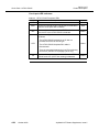
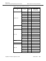
The following table provides an overview of the functions supported by the
AnyMedia Access System CTU DTP101, CTU DTP102, and CTU DTP103 circuit
packs.
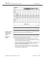
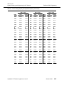
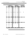
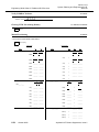
Table 4-1. $11(
%%6'#@.23A.23A
.232-
Circuit Pack
Supported Functions
• Operations-related functions, such as TR-08a and GR-303
channel and drop testing and local metallic test access
• Interfaces to external systems, such as the following:
DTP101
— RTU
— CIT port for a GSI or TL1SI
— 10BaseT LAN.
DTP102
DTP103
• Same functions and interfaces as the DTP101
• Local digital test access and digital data service testing.
• Same functions and interfaces as the DTP101
• Time domain reflectometry (TDR) testing
a
TR-08 is not supported for IAT applications.
For a detailed description of the CTU DTP101, CTU DTP102, and CTU DTP103
circuit packs, see the AnyMedia® Access System, Applications, Planning, and
Ordering Guide.
AnyMedia IAT Feature Supplement, Issue 5
October 2002
4-9
,4
2.%
2-8233
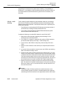
Circuit Pack—IATS2 LPS100
Overview
4
The IATS2 LPS100 operates in CO, RT, and customer premises environments. It
may not be used in outside plant cabinets.
The IATS2 LPS100 plugs into any of the 16 AP slots of an AnyMedia FAST shelf
and provides the interface functions between the IAT and the AnyMedia RT. An
IATS2 LPS100 provides two DS1 interfaces, each of which supports 24 DS0
channels for switched voice, nonswitched voice, or digital data services.
A FAST shelf fully equipped with 16 IATS2 LPS100s supports 768 customer lines.
The actual number of customer lines served depends on the mix of GR-303 and
INA VRTs supported on the AnyMedia RT.
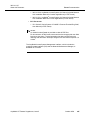
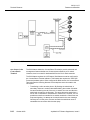
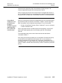
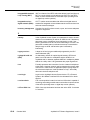
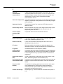
A functional block diagram of the IATS2 LPS100 is shown in Figure 4-3 on page
4-12, the faceplate is shown in Figure 4-4 on page 4-13, and Table 4-1 on page
4-14 lists the functions and colors of the LED indicators.
Provisionable parameters are described in Configuration Management—DS1 IAT
Server Port Provisioning on page 5-17.
Features and
functions
The IATS2 LPS100 supports the following features and functions:
Two DS1 line interfaces
4
• Supports an AMI bipolar interface and provisionable B8ZS coding
• Provides transmit pulse shaping with provisionable equalization
• Supports receive pulse regeneration and clock recovery
• Monitors pulse density and signal level for loss of signal
• Supports AIS transmission
• Monitors bipolar violations
• Provides DS1 bank loopbacks.
DS1 framing, robbed-bit signaling, and data link
4
• Supports ESF framing plus D4 framing
• Supports per-channel robbed-bit signaling and per-channel zero byte
substitution (ZBS)
• Provides transmit and receive elastic stores for rate conversion and
controlled slips
• Supports the ESF facility data link (HDLC messages, bit-oriented codes,
and idle)
• Sources and monitors AIS and yellow facility alarms
4-10
October 2002
AnyMedia IAT Feature Supplement, Issue 5
,4
2.%
2-8233
• Monitors for framing bit errors and CRC-6 errors.
!!
• Provides PCM channel and signaling mappings between the framers and
the COMDACs
• Provides signaling translation between the IAT and the FAST shelf
• Detects and reports on-hook and off-hook signaling states
• Supports per-channel signaling freeze and per-channel trunk processing
• Supports simplex and duplex COMDAC operation and COMDAC side
switches.
Synchronization and clock distribution
4
• Synchronizes to the reference clock coming from the active COMDAC
• Provides a local clock source for AIS transmission in the event there is no
reference clock from the active COMDAC
• Generates and distributes clocks to the data flow router and concentrator,
framers, and line interfaces.
"#$
• Provisions the line interfaces, framers, time slot interchanger, and signaling
translator (including the signaling translation maps)
• Supports peripheral communications with the active COMDAC
• Translates HDLC messages to and from AIU-compatible UART messages
for the active COMDAC
• Monitors and controls facility alarms (e.g., AIS and yellow alarms)
• Controls loopbacks
• Controls IATS built-in self-test (BIST)
• Supports enhanced inventory
• Supports performance monitoring of the upstream line interfaces from the
IAT.
AnyMedia IAT Feature Supplement, Issue 5
October 2002
4-11
,4
2.%
2-8233
Functional block
diagram
Figure 4-3.
4-12
October 2002
IATS2 LPS100 Functional Block Diagram
AnyMedia IAT Feature Supplement, Issue 5
,4
2.%
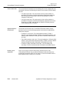
Equipment
description
2-8233
Circuit pack faceplate
Figure 4-4.
IATS2 LPS100 Faceplate
AnyMedia IAT Feature Supplement, Issue 5
4
October 2002
4-13
,4
2.%
2-8233
Circuit pack LED indicators
4
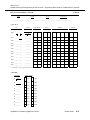
Table 4-1. 233%!/.
LED
Function
Color
FAULT
Lit when an internal IATS2 LPS100 failure is detected or
when the circuit pack fails to initialize.
Red
CLF
Lit when a failure of either IAT/RT carrier link from the
IAT to the IATS2 LPS100 is detected.
Yellow
Lit when a configuration error or a mismatch is detected,
as follows:
CFG
• The IATS2 LPS100 is placed in an AP slot not
provisioned for the IAT Server type.
• The IATS2 LPS100 faceplate DS1 cable is
disconnected.
Yellow
• There is a mismatch between the host T0 provisioning
and the IAT phantom CU equipage (IAT01 only).
IAT
4-14
October 2002
Lit when a failure of either line from the IATS2 LPS100 to
the IAT (IAT/RT link working) is detected.
Yellow
AnyMedia IAT Feature Supplement, Issue 5
,4
2.%
2-823
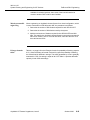
Circuit Pack—IATS4 LPS104
Overview
4
The IATS4 LPS104 operates in CO, RT, and customer premises environments. It
may not be used in outside plant cabinets.
The IATS4 LPS104 plugs into any of the 16 AP slots of an AnyMedia FAST shelf
and provides the interface functions between the IAT and the AnyMedia RT. An
IATS4 LPS104 provides 4 HDSL2 interfaces, each of which transports a payload
of 24 DS0 channels for switched voice, nonswitched voice, or digital data
services.
The IATS4 LPS104 uses the standard VF cable, which is used for most of the
AnyMedia APs. Even though this VF cable contains 32 pairs, only pairs 1, 3, 5,
and 7 are used for the HDSL2 interfaces of the LPS104. The remaining 28 pairs
are not used for the LPS104.
A FAST shelf fully equipped with 16 IATS4 LPS104s supports 1536 customer
lines. The actual number of customer lines served depends on the mix of GR-303
and INA VRTs supported on the AnyMedia RT.
The IATS4 LPS104 requires a FAST shelf equipped with a COMDAC COM102;
the IATS4 LPS104 will not operate with the COMDAC COM100 or the COMDAC
COM101.
Figure 4-3 on page 4-12 shows a functional block diagram of the IATS4 LPS104,
Figure 4-4 on page 4-13 shows the faceplate, and Table 4-1 on page 4-14 lists the
functions and colors of the LED indicators.
Provisionable parameters are described in Configuration Management—HDSL2
IAT Server Port Provisioning on page 5-19.
Features and
functions
The IATS4 LPS104 supports the following features and functions:
Four HDSL2 line interfaces
4
• Provides PAM, demodulation, echo cancellation, and signal shaping
(conforms to overlapped PAM transmission with interlocking spectra
[OPTIS] power spectral density template)
• Provides upstream and downstream HDSL2 frame mapping
• Provides forward error correction
• Provides clock generation and timing recover
• Supports local and remote digital loopback
• Supports access to the HDSL2 embedded operations (for host-to-host
communications)
AnyMedia IAT Feature Supplement, Issue 5
October 2002
4-15
,4
2.%
2-823
• Provides secondary lightning and power cross protection.
Test access to the HDSL2 tip/ring pairs
4
• Supports splitting, look-out test access to each of the HDSL2 interfaces,
one at a time
DS1 framing, robbed-bit signaling, and data link
4
• Supports ESF framing and SF framing
• Supports per-channel robbed-bit signaling and per-channel zero byte
substitution (ZBS)
• Provides transmit and receive elastic stores for rate conversion and
controlled slips
• Supports the ESF facility data link (HDLC messages, bit-oriented codes,
and idle)
• Sources and monitors AIS and yellow facility alarms
• Monitors for framing bit errors and CRC-6 errors.
Data flow management and signaling processing
4
• Provides PCM channel and signaling mappings between the framers and
the COMDACs
• Provides signaling translation between the IAT and the FAST shelf
• Detects and reports on-hook and off-hook signaling states
• Supports per-channel signaling freeze and per-channel trunk processing
• Supports simplex and duplex COMDAC operation and COMDAC side
switches.
Synchronization and clock distribution
4
• Synchronizes to the reference clock coming from the active COMDAC
• Provides a local clock source for AIS transmission in the event there is no
reference clock from the active COMDAC
• Generates and distributes clocks to the data flow router and concentrator,
framers, and line interfaces.
IATS control
4
• Provisions the line interfaces, framers, time slot interchanger, and signaling
translator (including the signaling translation maps)
• Supports peripheral communications with the active COMDAC
• Translates HDLC messages to and from AIU-compatible UART messages
for the active COMDAC
• Monitors and controls facility alarms (e.g., AIS and yellow alarms)
• Controls loopbacks
4-16
October 2002
AnyMedia IAT Feature Supplement, Issue 5
,4
2.%
2-823
• Controls IATS built-in self-test (BIST)
• Supports enhanced inventory
• Supports performance monitoring of the HDSL2 line interfaces and the DS1
payloads from the IAT.
Functional block
diagram
Figure 4-5.
IATS4 LPS104 Functional Block Diagram
AnyMedia IAT Feature Supplement, Issue 5
October 2002
4-17
,4
2.%
2-823
Equipment
description
Circuit pack faceplate
Figure 4-6.
4-18
October 2002
4
IATS4 LPS104 Faceplate
AnyMedia IAT Feature Supplement, Issue 5
,4
2.%
2-823
Circuit pack LED indicators
4
Table 4-1. 23%!/.
LED
Function
Color
FAULT
Lit when an internal IATS4 LPS104 failure is detected or
when the circuit pack fails to initialize
Red
CLF
Lit when a failure of one or more IAT/RT carrier links
from the IAT to the IATS4 LPS104 is detected.
Yellow
Lit when a configuration error or a mismatch is detected,
as follows:
CFG
• The IATS4 LPS104 is placed in an AP slot not
provisioned for the IAT Server type.
• The IATS4 LPS104 faceplate HDSL2 cable is
disconnected.
Yellow
• There is a mismatch between the host T0 provisioning
and the IAT phantom CU equipage (IAT01 only).
IAT
Lit when a failure of one or more lines from the IATS4
LPS104 to the IAT (IAT/RT link working) is detected.
Yellow
F
AnyMedia IAT Feature Supplement, Issue 5
October 2002
4-19
,4
2.%
2-8+23+
Circuit Pack—IATS5 LPS105
Overview
4
The IATS5 LPS105 operates in CO, RT, and customer premises environments. It
may not be used in outside plant cabinets.
The IATS5 LPS105 plugs into any of the 16 AP slots of an AnyMedia FAST shelf
and provides the interface functions between the IAT and the AnyMedia RT. An
IATS5 LPS105 provides five DS1 interfaces, each of which supports 24 DS0
channels for switched voice, nonswitched voice, or digital data services.
A FAST shelf fully equipped with 16 IATS5 LPS105 APs supports 1920 customer
lines. The actual number of customer lines served depends on the mix of GR-303
and INA VRTs supported on the AnyMedia RT.
The IATS5 LPS105 requires a FAST shelf equipped with the COMDAC COM102;
the IATS5 LPS105 will not operate with the COMDAC COM100 or the COMDAC
COM101.
Figure 4-3 on page 4-12 shows a functional block diagram of the IATS5 LPS105,
Figure 4-4 on page 4-13 show the faceplate, and Table 4-1 on page 4-14 lists the
functions and colors of the LED indicators.
Provisionable parameters are described in Configuration Management—DS1 IAT
Server Port Provisioning on page 5-17.
Features and
functions
The IATS5 LPS105 supports the following features and functions:
Five DS1 line interfaces
4
• Supports an AMI bipolar interface and provisionable B8ZS coding
• Provides transmit pulse shaping with provisionable equalization
• Supports receive pulse regeneration and clock recovery
• Monitors pulse density and signal level for loss of signal
• Sources AIS transmission
• Monitors for bipolar violations
• Provides DS1 line loopbacks and bank loopbacks.
DS1 framing, robbed-bit signaling, and data link
4
• Supports ESF framing and SF framing
• Supports per-channel robbed-bit signaling and per-channel zero byte
substitution (ZBS)
• Provides transmit and receive elastic stores for rate conversion and
controlled slips
4-20
October 2002
AnyMedia IAT Feature Supplement, Issue 5
,4
2.%
2-8+23+
• Supports the ESF facility data link (HDLC messages, bit-oriented codes,
and idle)
• Sources and monitors AIS and yellow facility alarms
• Monitors for framing bit errors and CRC-6 errors.
Data flow management and signaling processing
4
• Provides PCM channel and signaling mappings between the framers and
the COMDACs
• Provides signaling translation between the IAT and the FAST shelf
• Detects and reports on-hook and off-hook signaling states
• Supports per-channel signaling freeze and per-channel trunk processing
• Supports simplex and duplex COMDAC operation and COMDAC side
switches.
Synchronization and clock distribution
4
• Synchronizes to the reference clock coming from the active COMDAC
• Provides a local clock source for AIS transmission in the event there is no
reference clock from the active COMDAC
• Generates and distributes clocks to the data flow router and concentrator,
framers, and line interfaces.
IATS control
4
• Provisions the line interfaces, framers, time slot interchanger, and signaling
translator (including the signaling translation maps)
• Supports peripheral communications with the active COMDAC
• Translates HDLC messages to and from AIU-compatible UART messages
for the active COMDAC
• Monitors and controls facility alarms (e.g., AIS and yellow alarms)
• Controls loopbacks
• Controls IATS built-in self-test (BIST)
• Supports enhanced inventory
• Supports performance monitoring of the upstream DS1 line interfaces from
the IAT.
AnyMedia IAT Feature Supplement, Issue 5
October 2002
4-21
,4
2.%
2-8+23+
Functional block
diagram
Figure 4-7.
4-22
October 2002
IATS5 LPS105 Functional Block Diagram
AnyMedia IAT Feature Supplement, Issue 5
,4
2.%
Equipment
description
2-8+23+
Circuit pack faceplate
Figure 4-8.
IATS5 LPS105 Faceplate
AnyMedia IAT Feature Supplement, Issue 5
4
October 2002
4-23
,4
2.%
2-8+23+
Circuit pack LED indicators
4
Table 4-1. +23+%!/.
LED
Function
Color
FAULT
Lit when an internal IATS5 LPS105 failure is detected or
when the circuit pack fails to initialize.
Red
CLF
Lit when a failure of one or more IAT/RT carrier links
from the IAT to the IATS5 LPS105 is detected.
Yellow
Lit when a configuration error or a mismatch is detected,
as follows:
CFG
• The IATS5 LPS105 is placed in an AP slot not
provisioned for the IAT Server type.
• The IATS5 LPS105 faceplate DS1 cable is
disconnected.
Yellow
• There is a mismatch between the host T0 provisioning
and the IAT phantom CU equipage (IAT01 only).
IAT
4-24
October 2002
Lit when a failure of one or more lines from the IATS5
LPS105 to the IAT (IAT/RT link working) is detected.
Yellow
AnyMedia IAT Feature Supplement, Issue 5
OAM&P for IAT Services
5
Overview
5
5
This chapter describes the OAM&P operations of the AnyMedia Access System
for IAT services.
OAM&P Interface
5-2
Configuration Management
5-3
Configuration Management—Memory Administration
5-4
Configuration Management—Software Management
5-5
Configuration Management—Service Activation
5-6
Configuration Management—Provisioning
5-7
Configuration Management—Slot Provisioning
5-8
Configuration Management—Logical Subshelf Provisioning
5-9
Configuration Management—Line Termination Provisioning
5-10
Configuration Management—T0 Provisioning
5-14
Configuration Management—DS1 IAT Server Port Provisioning
5-17
Configuration Management—HDSL2 IAT Server Port Provisioning
5-19
Configuration Management—VFDE/ClearReach Feature
5-21
Configuration Management—Inventory Management
5-22
Configuration Management—Synchronization Provisioning
5-24
Configuration Management—Facility Data Link
5-25
Configuration Management—Maintenance
5-26
Performance Management
5-27
AnyMedia IAT Feature Supplement, Issue 5
October 2002
5-1
,4
$*G2
1
$*G2
OAM&P Interface
Overview
5
The GSI of the AnyMedia Management Interface supports the operations that
manage the AnyMedia Access System functional areas for OAM&P operations via
TL1 command execution.
For more details, refer to Management Interface in Chapter 6, Traditional DLC
Interfaces, of the AnyMedia® Access System, Applications, Planning, and
Ordering Guide.
5-2
October 2002
AnyMedia IAT Feature Supplement, Issue 5
,4
$*G2
1
* Configuration Management
Overview
5
Configuration Management is the system activity for operations that control and
provision the system, including the following:
• Memory administration—Used to manage the nonvolatile data storage
(NVDS) of the AnyMedia Access System
• Software management—Used to manage the nonvolatile program storage
(NVPS) of the AnyMedia Access System
• Service provisioning—Process of preparing a port circuit for service by
defining the function of the port circuit and setting its parameters
• VFDE/ClearReach feature—Improved modem performance may be
achieved on certain locally switched GR-303 calls when the VFDE feature is
enabled on the AnyMedia Access System, the ClearReach feature is
enabled on the ConnectReach Terminal or ConnectReach 200, and the
AnyMedia Access System is hosted by a 5ESS switch with VFDE enabled
• Inventory management—System activity of collecting, updating, and
reporting data on system equipage and system status
• Synchronization provisioning—Controls the synchronization mode of the
AnyMedia Access System and its synchronization reference sources
• Facility data link—Opens a channel to communicate to the IAT01
(ConnectReach Terminal and ConnectReach 200) via the data link on the
DS1 or HDSL2 facility between the FAST shelf and the IAT.
AnyMedia IAT Feature Supplement, Issue 5
October 2002
5-3
,4
$*G2
1
* 8* ' Configuration Management—Memory
Administration
5
Overview
Memory administration is used to manage the NVDS of the AnyMedia Access
System. NVDS contains the host terminal provisioning data including slot
provisioning, logical subshelf provisioning, line termination provisioning, T0
provisioning, and IAT Server port provisioning.
Data storage
The system has the following types of data storage:
• Volatile data storage, which is in the RAM
• NVDS, which is implemented using a FLASH memory device on the
COMDAC circuit pack.
The system periodically audits the NVDS. If the system is in a simplex
configuration, it checks the self-consistency of the NVDS. If the system is in a
duplex configuration, it checks self-consistency and mutual-consistency of both
copies of the NVDS.
5-4
October 2002
AnyMedia IAT Feature Supplement, Issue 5
,4
$*G2
1
* 8
(
* Configuration Management—Software
Management
5
Overview
Software management is used to manage the NVPS of the AnyMedia Access
System. NVPS is the nonvolatile memory on the COMDAC and the AFM used to
store the program image.
For more details, refer to the AnyMedia® Access System, Applications, Planning,
and Ordering Guide.
AnyMedia IAT Feature Supplement, Issue 5
October 2002
5-5
,4
$*G2
1
* 811
Configuration Management—Service
Activation
Overview
5
Service activation is the process of preparing the AnyMedia Access System for
service by configuring the cross-connections between its bandwidth management
entities (e.g., feeder resources, VRTs, and VBs) and setting any required options.
For more details, refer to the AnyMedia® Access System, Applications, Planning,
and Ordering Guide.
5-6
October 2002
AnyMedia IAT Feature Supplement, Issue 5
,4
$*G2
1
* 821
Configuration Management—
Provisioning
Overview
5
The following provisioning functions for the AnyMedia Access System are
described in this section:
• Slot provisioning
• Logical subshelf provisioning
• Line termination provisioning
• T0 provisioning
• DS1 IAT Server port provisioning
• HDSL2 IAT Server port provisioning.
AnyMedia IAT Feature Supplement, Issue 5
October 2002
5-7
,4
$*G2
1
* 8!21
Configuration Management—Slot
Provisioning
5
Overview
Slot provisioning is the process of preparing a slot in the FAST shelf to work with a
certain type of AP. This section covers slot provisioning for an IAT Server.
Slot provisioning
The IAT Server is an AP that provides two distribution DS1 ports. A total of 16 IAT
Servers may be installed in a FAST shelf, serving up to 80 IATs. Each slot in the
FAST shelf that is to be equipped with an IAT Server must be provisioned using
the ENT-PACK TL1 command, with pack type=IATSVR. The provisioning of a slot
may be verified using the RTRV-PACK TL1 command. The provisioning of a slot
may be deleted with the DLT-PACK TL1 command.
5-8
October 2002
AnyMedia IAT Feature Supplement, Issue 5
,4
$*G2
1
Configuration Management—Logical
Subshelf Provisioning
* 8!6#!
21
5
Overview
An IAT is considered a subshelf of the AnyMedia Access System. Logical subshelf
provisioning includes assigning a logical subshelf number and identifying the
subshelf type to the AnyMedia Access System. Also included is the logical
subshelf to physical IAT Server port association.
Logical subshelf
provisioning
Each IAT connected to a particular FAST shelf must be assigned a logical
subshelf number in the AnyMedia Access System, and the logical subshelf
number must be associated with a physical IAT Server port.
The type of IAT must also be identified to the AnyMedia Access System when the
logical subshelf number is assigned. Two types of IATs are supported by the
AnyMedia Access System—IAT01 and IAT02. The subshelf type IAT01 refers to
the proprietary (modified D4) type used by both the ConnectReach Terminal and
ConnectReach 200. The subshelf type IAT02 refers to the industry standard
(nonproprietary) D4 type of IAT.
The ENT-SUBSHELF TL1 command is used to assign the logical subshelf number
and identify the subshelf type of the IAT to the AnyMedia Access System. The
RTRV-SUBSHELF TL1 command is used to verify the subshelf provisioning, and
the DLT-SUBSHELF TL1 command may be used to delete the logical subshelf
provisioning.
Logical to physical
provisioning
The logical subshelf also must be associated with a physical IAT Server port via
the ENT-CRS-SUBSHELF TL1 command. The logical subshelf association with a
physical IAT Server port is verified with the RTRV-CRS-SUBSHELF TL1 command
and may be deleted with the DLT-CRS-SUBSHELF TL1 command.
AnyMedia IAT Feature Supplement, Issue 5
October 2002
5-9
* 8 21
Configuration Management—Line
Termination Provisioning
,4
$*G2
1
5
Overview
Line termination provisioning is the process of preparing a subscriber line for
service by defining its function and setting any required options. This section
deals with IAT specific provisioning.
Service provisioning
considerations
IAT services include traditional message telephone service (POTS and locally
switched special services) and Nx64 (N timeslots of 64 kbps each) digital data
service. These services are supported via an IAT at the customer premises and
an IAT Server in the FAST shelf. The IAT Server contains no physical option
switches; instead, its function is controlled by electronic service provisioning
information that is stored in NVDS in the AnyMedia Access System. Software in
the AnyMedia Access System compares this stored service provisioning
information with the ConnectReach Terminal or ConnectReach 200 equipage and,
if they are compatible, the software conditions the hardware to provide the desired
service.
The following significant pieces of information are required to provision service on
any interface:
• The physical subscriber line must be assigned to a logical line on an inservice VRT or to a logical DS0 on an INA VB. This assignment is
represented by a T0 cross-connection.
• Transmission and signaling parameters for the desired service must be
provided. The information is represented by a T0 provisioning record. For
lines served by a GR-303 VRT, the information can be entered via a TL1
command from an OS, a TL1SI, or the GSI. Alternatively, a compatible CO
switch can provide the necessary information via its GR-303 EOC. The
Lucent 5ESS®, switch, the Nortel DMS-100 switch, and the Siemens EWSD
support either EOC or OS provisioning.
The AnyMedia Access System associates the transmission and signaling
parameters (the T0 records) with the logical lines of the system. The logical lineto-physical port assignment information (the T0 cross-connections) permits the
system software to transfer these parameters to the correct hardware port.
Note that IAT lines cannot be cross-connected to TR-08 VRTs.
Physical-to-logical
port provisioning
5-10
October 2002
To establish service on a subscriber line of the AnyMedia Access System, the
physical subscriber line to an IAT must be assigned to a logical line on a VRT or
INA VB within the system. The AnyMedia Access System may contain up to 3
GR-303 VRTs, and/or up to 20 INA VBs, subject to the limit imposed by the 20
available DS1 network interfaces. A physical subscriber line may be assigned to
AnyMedia IAT Feature Supplement, Issue 5
,4
$*G2
1
* 8 21
only 1 logical line on 1 VRT or INA VB; similarly, a logical line can be assigned to
only 1 physical subscriber line.
A GR-303 VRT can support any number of IAT lines up to the full 1920-line
maximum capacity of the fully populated FAST shelf. The logical lines of each
GR-303 VRT are identified by CRVs, which may be any of 1920 integer values
from 1 to 2048. A physical subscriber line in the system can be assigned to any
CRV of a GR-303 VRT.
An INA VB supports 24 logical DS0 timeslots and a maximum of 24 physical lines.
The logical DS0 timeslots are numbered from 1 to 24. A physical subscriber line
may be assigned to any logical DS0 within any INA VB.
The association between logical lines and physical lines can be changed by
deleting a cross-connection and entering a new cross-connection. This permits
the physical appearance of a logical line to be easily moved from one physical
port to another physical port without changing the serving switch’s database.
Transmission and
signaling parameter
provisioning
Transmission and signaling information must be provided for each subscriber line
prior to service availability (i.e., the AnyMedia Access System provides no default
provisioning).
The per-line provisioning information may be entered via TL1 commands from a
remote OS, a TL1SI, or the GSI. Alternatively, the information for POTS/SPOTS®
and DID applications can be provisioned via the GR-303 EOC by digital switches
that implement this functionality. The TL1 and EOC interfaces act on a single
instance of the AnyMedia Access System’s nonvolatile data store so that absolute
provisioning information integrity is maintained within the system, regardless of
the source of a provisioning data change. Changes to the provisioning information
made via the GR-303 EOC may be viewed via the TL1 interface, and vice versa.
However, not all provisioning features are available via the EOC interface. The
choice of TL1 versus EOC provisioning for GR-303 applications, or some hybrid of
the two provisioning types, will be dictated by the operations plan of the local
exchange carrier and by the capabilities of the LDS.
The TL1 provisioning information is aligned with Telcordia Technologies, Inc.
GR-199. The per-subscriber information consists of a CLEI code, a generic
signaling function (GSFN) code which specifies the circuit’s signaling protocol,
and a variable number of additional parameters specific to each GSFN code.
The CLEI code information is not required to provide service. The field may be
used if desired to indicate the intended AP type for a service. However, the
system software will not deny service to a subscriber line because the provisioned
CLEI code does not match the equipped CLEI code of an AP. The CLEI field may
remain empty without affecting the service capability of a subscriber line. For IAT
services, the CLEI code is not used.
AnyMedia IAT Feature Supplement, Issue 5
October 2002
5-11
* 8 21
,4
$*G2
1
The GSFN codes supported in the AnyMedia Access System for the IAT feature
are as follows:
• DFLT—default POTS/SPOTS
• 2LS—loop start
• 2GS—ground start
• 2RVT—direct inward dialing/dial pulse terminate (DID/DPT)
• FXOD—foreign exchange office
• NO—transmission only
• FXS0—foreign exchange station
• EM0—E&M
• OCU0—64 kbps clear channel data and multiple channels of 64 kbps data
(Nx64).
Additional transmission and signaling parameters may be required depending
upon the GSFN code of the circuit being provisioned.
For IAT01 (ConnectReach Terminal and ConnectReach 200), the system software
compares the transmission and signaling information for each logical line with the
associated IAT hardware. If the hardware is compatible with the provisioned
GSFN code and the associated parameters, then the appropriate information is
transferred to the hardware registers and the line is placed in service.
For lines served on an IAT02, the local service state of the line is in service if the
IAT Server is installed, the IAT Server is correctly provisioned, and the DS1 to the
IAT is operational. Proper equipage and provisioning at the IAT02 is required for
services to work, but these are not verified by the AnyMedia Access System.
Provisioning service
activation
5-12
October 2002
Service activation for IAT services requires that feeder and subscriber lines be
associated with a VRT/VB through T1 and T0 cross-connections, respectively,
and that T0 provisioning data be entered for the desired service. Finally, the
required physical circuit packs must be equipped. Figure 5-1 on page 5-13
represents the composite provisioning data required to bring a single subscriber
line into service on a GR-303 VRT, with examples of the associated TL1
commands. Note that slot provisioning, logical subshelf provisioning, and
association of a logical subshelf with a physical IAT Server port are not shown in
this figure.
AnyMedia IAT Feature Supplement, Issue 5
,4
$*G2
1
* 8 21
.
Figure 5-1.
Provisioning Data for a GR-303 POTS Subscriber Line
A GR-303 VRT supports DS0 concentration (i.e., it can support more physical
subscriber lines than trunk timeslots). The subscriber lines will be dynamically
assigned to available trunk timeslots as required, under control of the GR-303
switch.
The AnyMedia Access System imposes few restrictions on line termination
provisioning. Therefore, it is possible to define some unusual combinations of
VRTs/VBs and services (e.g., a coin line may be provisioned in an INA VB,
although such a configuration may have no practical application).
The AnyMedia Access System has limited provisioning memory capacity that can
accommodate provisioning records for up to 2048 subscriber lines. This is greater
than the maximum number of physical lines that can be supported by the system.
This permits two provisioning records to be created for a limited number of lines
during load balancing or service rollover operations.
The T0 records for retired lines should always be deleted so that the provisioning
resources of the AnyMedia Access System will not be exhausted.
AnyMedia IAT Feature Supplement, Issue 5
October 2002
5-13
,4
$*G2
1
* 8321
Configuration Management—T0
Provisioning
Overview
5
The logical lines of VRTs/VBs in the AnyMedia Access System must be
provisioned with appropriate T0 data to activate subscriber service. The system
provides no default T0 provisioning data.
The T0 data are stored in nonvolatile data memory on the COMDAC circuit pack
and transferred to the associated IAT Server as needed. The T0 data can be
managed via the ENT-T0, ED-T0, RTRV-T0, and DLT-T0 TL1 commands.
Alternatively, for the GR-303 VRT, the data can be managed by the GR-303 LDS
via its EOC. The TL1 and EOC interfaces act on the same nonvolatile data
memory, so that consistent data are maintained regardless which interface
performs the provisioning. The current memory contents can be retrieved by
either interface.
IAT Server
replacement
When an IAT Server is replaced with an identical IAT Server, the new IAT Server
will be provisioned automatically with the current T0 data.
T0 parameters
The T0 data for a logical line defines the service function of the associated
subscriber line. The key parameter in the T0 record is the GSFN.
The GSFN codes available via the IAT feature are as follows:
• DFLT—is applicable to both IAT01 and IAT02. Lines that are provisioned
with the DFLT GSFN provide POTS/SPOTS service. These lines can be
created from the GR-303 LDS or via the TL1 commands.
• 2LS—is applicable to both IAT01 and IAT02. Lines that are provisioned with
the 2LS GSFN provide loop start service. These lines can be created from
the GR-303 LDS or via the TL1 commands.
• 2GS—is applicable to both IAT01 and IAT02. Lines that are provisioned with
the 2GS GSFN provide ground start service. These lines can be created
from the GR-303 LDS or via the TL1 commands.
• 2RVT—is applicable to both IAT01 and IAT02. Lines that are provisioned
with the 2RVT GSFN provide two-wire DID service, with either dial pulse or
multifrequency addressing. These lines can be created from the GR-303
LDS or via the TL1 commands.
• FXOD—is applicable to IAT02. Lines that are provisioned with the FXOD
GSFN provide foreign exchange—office end, loop-start or ground-start
signaling, with normal or reversed signaling leads, and with or without toll
diversion. These lines can be created via the TL1 commands.
5-14
October 2002
AnyMedia IAT Feature Supplement, Issue 5
,4
$*G2
1
* 8321
• NO—is applicable to IAT02. Lines that are provisioned with the NO GSFN
provide private line transmission-only service. The NO function is used for
private lines (voice or data). These lines can be created via the TL1
commands.
• FXS0—is applicable to both IAT01 and IAT02. Lines that are provisioned
with the FXS0 GSFN provide foreign exchange—subscriber end, loop-start
or ground-start signaling, with normal or reversed signaling leads, and with
or without toll diversion. These lines can be created via the TL1 commands.
• EM0—is applicable to IAT02. Lines that are provisioned with the EM0
GSFN provide E&M signaling, Type 1 or Type 2. Both Type I and II signaling
connections are supported. These lines can be created via the TL1
commands.
• OCU0—is applicable to both IAT01 and IAT02. Lines that are provisioned
with the OCU0 GSFN provide private line data service. The rate is 64 kbps.
These lines can be created via the TL1 commands. Nx64 services are
provided by using multiple sequential DS0s, all provisioned with the OCU0
GSFN.
Depending on the GSFN code selected for a T0 record, a number of additional
parameters can be provisioned for the affected subscriber line. These parameters
are summarized in Figure 5-2 on page 5-16. Default values are provided for all
parameters.
AnyMedia IAT Feature Supplement, Issue 5
October 2002
5-15
,4
$*G2
1
* 8321
Figure 5-2.
5-16
TL1 Provisioning Parameters for T0 Objects—IAT
October 2002
AnyMedia IAT Feature Supplement, Issue 5
,4
$*G2
1
* 8.12
21
Configuration Management—DS1 IAT
Server Port Provisioning
5
Overview
The DS1 IAT Server ports in the AnyMedia FAST shelf terminate the distribution
DS1s from IATs. The IAT Server supports a DS1 interface as specified in
T1.102-1993. This DS1 interface is intended to be used as an intrasite or
intraoffice interconnect. The DS1 interface supports a limited transmission
distance from the FAST shelf to the DSX-1 cross connect panel depending on the
type of cable used, up to 655 feet for 22-gauge wire.
Line code
The AMI line code is supported by the DS1 interface. AMI is a binary signal in
which no pulse indicates a binary 0, and a pulse with polarity opposite to the
previous pulse indicates a 1. AMI is also called a bipolar signal. The ones density
assurance techniques supported by the line code include the following:
• B8ZS
• ZCS.
These techniques may be provisioned individually for each distribution DS1 via a
TL1 command.
B8ZS
The B8ZS technique replaces any sequence of eight consecutive zeros with a
code to represent the eight zero bits. B8ZS is the default technique and will
ensure a sufficient ones density in the DS1 signal without affecting the payload.
The B8ZS technique is required for IAT01 interfaces.
ZCS
ZCS may be required for some IAT02 DS1 signals. When a DS1 signal is
provisioned for ZCS, the system employs a ZCS technique on the DS0 signals
that carry VF services in that DS1. This ZCS technique replaces the seventh bit
(second least significant bit) with a binary one in each DS0 that contains an all
zero code.
Framing formats
The system supports two different DS1 frame formats:
• ESF
• SF (traditional D4 framing used for DS1 facilities).
AnyMedia IAT Feature Supplement, Issue 5
October 2002
5-17
* 8.12
21
,4
$*G2
1
The SF and ESF formats are defined in T1.107-1988. IAT01 DS1 signals must be
provisioned with the ESF format. IAT02 DS1 signals may be provisioned for either
the SF or ESF format.
Equalization
The equalization for DS1 interface may be provisioned to match the distance, in
feet, from the IAT Server to the DSX-1 cross-connect. EQLZ may be provisioned
with any value from 0 to 655.
Signal degrade
threshold
The signal degrade threshold (DGTH) is the value that determines the
performance monitoring threshold before an alert is sent to the operations support
system. Values are 4 (bit error rate of 10-4), 5 (10-5), 6 (10-6), and 7 (10-7).
5-18
October 2002
AnyMedia IAT Feature Supplement, Issue 5
,4
$*G2
1
* 89.1
221
Configuration Management—HDSL2
IAT Server Port Provisioning
Overview
5
The HDSL2 IAT Server ports in the AnyMedia FAST shelf terminate the
distribution HDSL2 facilities from IATs. The IAT Server supports the HDSL2
interface as specified in T1E1.4/99-006R4. HDSL2 provides full-duplex
transmission of full 1.544 Mbps DS1 payload. The HDSL2 may be used in the
outside plant. The HDSL2 interface supports a transmission distance from the
FAST shelf to the IAT depending on the type of cable used, up to 12,000 feet of
24-gauge wire. If a 26-gauge cable is used, it may not exceed 9,000 feet.
The HDSL2 facility encapsulates a DS1 signal: all the DS1 provisioning
parameters are therefore available with HDSL2. Although the EQLZ parameter is
available and may be provisioned, it is ignored by the HDSL2 IAT Server, since it
has no meaning for the HDSL2 interface.
Line code
The AMI line code is supported by the HDSL2 interface. AMI is a binary signal in
which no pulse indicates a binary 0, and a pulse with polarity opposite to the
previous pulse indicates a 1. AMI is also called a bipolar signal. The ones density
assurance techniques supported by the line code include the following:
• B8ZS
• ZCS.
These techniques may be provisioned individually for each distribution HDSL2
interface via a TL1 command.
B8ZS
The B8ZS technique replaces any sequence of eight consecutive zeros with a
code to represent the eight zero bits. B8ZS is the default technique and will
ensure a sufficient ones density in the DS1 signal without affecting the payload.
The B8ZS technique is required for IAT01 interfaces.
ZCS
ZCS may be required for some IAT02 DS1 signals. When a DS1 signal is
provisioned for ZCS, the system employs a ZCS technique on the DS0 signals
that carry VF services in that DS1. This ZCS technique replaces the seventh bit
(second least significant bit) with a binary one in each DS0 that contains an all
zero code.
Framing formats
The system supports two different DS1 frame formats:
AnyMedia IAT Feature Supplement, Issue 5
October 2002
5-19
* 89.12
21
,4
$*G2
1
• ESF
• SF (traditional D4 framing used for DS1 facilities).
The SF and ESF formats are defined in T1.107-1988. IAT01 DS1 signals must be
provisioned with the ESF format. IAT02 DS1 signals may be provisioned for either
the SF or ESF format.
Equalization
Equalization is ignored by the HDSL2 IAT Server.
Signal degrade
threshold
The signal degrade threshold (DGTH) is the value that determines the
performance monitoring threshold before an alert is sent to the operations support
system. Values are 4 (bit error rate of 10-4), 5 (10-5), 6 (10-6), and 7 (10-7).
5-20
October 2002
AnyMedia IAT Feature Supplement, Issue 5
,4
$*G2
1
Configuration Management—VFDE/
ClearReach Feature
* 8;./BClearReach
5
Overview
When the ClearReach feature is enabled in the ConnectReach Terminal or
ConnectReach 200 and the VFDE feature is enabled in the AnyMedia Access
System, robbed-bit signaling is suspended after calls are established, which
yields improved 56k modem performance. The ClearReach feature and VFDE are
applicable to locally switched loop start and ground start GR-303 calls when the
AnyMedia Access System is hosted by a 5ESS switch.
5ESS switch
The AnyMedia Access System must be hosted via a GR-303 interface on a 5ESS
switch. VFDE must be enabled in the 5ESS switch.
AnyMedia Access
System
VFDE must be enabled in the AnyMedia GR-303 VRT using the ALW-VFDE TL1
command.
ClearReach feature
The ClearReach feature must be activated in the ConnectReach Terminal or
ConnectReach 200.
AnyMedia IAT Feature Supplement, Issue 5
October 2002
5-21
,4
$*G2
1
* 81'* Configuration Management—Inventory
Management
5
Overview
Inventory Management is the system activity of collecting, updating, and reporting
data on system equipage and system status (i.e., IS or OOS). Inventory
Management includes reporting new equipment inventory upon installation,
storing equipment status, removing equipment inventory upon degrowth, and
reporting changes in inventory.
Retrievable
inventory items
Electronically readable inventory in the system can be retrieved on demand.
Retrievable inventory items for the IAT Server and the IAT01 terminal include the
following:
• TYPE—A mnemonic name that identifies the kind of equipment
• APP—The apparatus code that uniquely identifies the equipment function
• ICC—The interchangeability code stored in the form of Sm-n, where m is the
issue number and n is the series number
• CLEI—A 10-character code that identifies each circuit pack type
• ECI—A 6-character code that identifies each circuit pack type; the
equipment catalog item code corresponds to the bar coded label on the
faceplate of the circuit pack and is uniquely equivalent to the CLEI
• SLN—A 12-character code that uniquely identifies each circuit pack; the
serial number SLN includes the date and place of manufacture.
Primary and secondary service state information is also retrievable for the IAT
Server and the IAT terminal as follows:
• Primary service state—The valid values are as follows:
881
8$$8$
1
• Secondary service state—The valid values are as follows:
88!
8?8!&!
No inventory information is retrievable from the IAT02 terminal at the AnyMedia
Access System.
Physical data label
5-22
October 2002
On the front of each circuit pack is an electronically scannable bar code and a
human readable inventory data label. The human readable component contains
AnyMedia IAT Feature Supplement, Issue 5
,4
$*G2
1
* 81'
* the CLEI code, apparatus code, entity type, and interchangeability code. The bar
code scannable component of the label contains the equipment catalog item
code.
Reportable
database changes
Autonomous notification is provided when changes occur to the inventory
database as a result of the execution of provisioning commands, state changes,
or changes in the physical inventory.
AnyMedia IAT Feature Supplement, Issue 5
October 2002
5-23
* 8'#&
21
Configuration Management—
Synchronization Provisioning
,4
$*G2
1
5
Overview
Synchronization provisioning controls the synchronization mode of the AnyMedia
Access System and its synchronization reference sources.
Synchronization
modes
The synchronization mode is selected by a TL1 command.
The AnyMedia Access System typically operates in the line-timed mode. In this
mode, the system acquires its timing from a DS1 input signal. Two input signals
can be specified as the timing reference sources. If the active source fails, the
system automatically selects the duplicate source. When the system’s nonvolatile
data store is initialized at turn-up, the line-timed mode is selected as the initial
default synchronization mode for the system.
The AnyMedia Access System may be synchronized to external clock signals
from a building timing supply or from a SONET multiplexer. The system accepts
either DS1 (1.544 MHz) or composite clock (8 kHz and 64 kHz) external clock
signals. External clock signal inputs must be duplicated. The AnyMedia Access
System automatically switches to the duplicate clock signal if the active signal
fails.
The system can also operate in the free-running mode.
Switching between synchronization modes does not guarantee call preservation.
Line timing
synchronization
references
The line timing synchronization reference sources are also selected by TL1
provisioning.
The AnyMedia Access System supports two synchronization reference sources.
When the system’s nonvolatile data store is initialized at turn-up, the first DS1
inputs on each of the first two IODS1 circuit packs are selected as the initial
default reference sources.
5-24
October 2002
AnyMedia IAT Feature Supplement, Issue 5
,4
$*G2
1
Configuration Management—Facility
Data Link
* 8!'.-
5
Overview
The AnyMedia Access System operations interfaces (GSI, etc.) can open a
channel to communicate to the IAT01 terminals (ConnectReach Terminals and
ConnectReach 200) via the data link on the DS1 or HDSL2 facility between the
FAST shelf and the IAT.
Using the facility
data link
A communications channel from the FAST shelf to the IAT01 terminal may be
established using the ACT-IAT TL1 command. The communications channel is
provided via the data link on the DS1 facility to the IAT.
When the ACT-IAT command is executed, the TL1SI View window becomes the
IATSI view. The user is then logged into the ConnectReach Terminal or
ConnectReach 200 with Carrier privilege (see Chapter 11, OAM&P). The
communications channel is closed when the text string “close” is entered.
AnyMedia IAT Feature Supplement, Issue 5
October 2002
5-25
,4
$*G2
1
* 8*
Configuration Management—
Maintenance
Overview
5
The AnyMedia Access System provides the following maintenance functions
associated with IAT Servers:
• DS1 bank loopbacks at the IAT Server
• Metallic access to the HDSL2 drops on the IATS4 Server.
DS1 loopbacks
DS1 bank loopbacks may be established on a selected IAT Server port using the
Operate Loopback (OPR-LPBK) TL1 command. The loopback is released by
using the Release Loopback (RLS-LPBK) TL1 command. This loopback capability
is used only to test the IAT Server port transceiver: a network-originated payload
is not looped back.
Metallic test access
Metallic test access to a drop on the HDSL2 IATS4 Server may be obtained by
using the Connect-Test Access-Drop (CONN-TACC-DROP) TL1 command. Test
access is released by using the Disconnect-Test Access-Drop
(DISC-TACC-DROP) TL1 command.
5-26
October 2002
AnyMedia IAT Feature Supplement, Issue 5
,4
$*G2
1
2
* Performance Management
5
Overview
Performance Management is the system activity for collecting and reporting data
on the quality of transmission on the distribution (IAT) facilities (DS1 or HDSL2).
Performance Management operation includes data collection, specification of
thresholds for threshold crossing alerts (TCAs), generation of TCAs, and reports
of Performance Management data. Performance Management is performed at the
IAT Server end of the distribution DS1s.
DS1 (IAT)
Performance
Management
operation
For IAT DS1 Performance Management, the system continuously collects
Performance Management data internally, and an external system can retrieve
this data on a 15-minute or 24-hour basis. DS1 Performance Management aligns
with the recommendations in Telcordia Technologies, Inc. GR-820 for DS1 path
monitoring. These measurements also apply for the HDLS2 IAT facilities.
Performance
Management data
Performance Management data are collected for the following:
• Coding violations-path (CV-P)
• Severely errored framing seconds-path (SEFS-P)
• Controlled slip seconds-path (CSS-P)
• Errored seconds-line (ES-L)
• Errored seconds-path (ES-P)
• Severely errored seconds-path (SES-P)
• Unavailable seconds-path (UAS-P.)
Data are collected in 15-minute intervals. For each category, current and previous
15-minute Performance Management counts are stored. In addition, for all except
CV-P, 31 history counts are stored for a total of eight hours of data. All counts can
be retrieved from the interface to an OS and from a TL1SI or GSI/TL1SI view
interface.
Once a Performance Management count exceeds the threshold, an autonomous
message is generated to indicate a TCA. The threshold values can be set
externally for the individual Performance Management counts. TCA messages
can be inhibited.
Performance
Management
capabilities
Performance Management has general capabilities for DS1 via TL1 commands as
follows:
• Retrieve Performance Management information
AnyMedia IAT Feature Supplement, Issue 5
October 2002
5-27
,4
$*G2
1
2
* • Set and retrieve the threshold values for TCA generation
• Reset the Performance Management counts
• Report the occurrence of a TCA
• Allow/inhibit the TCA reporting.
5-28
October 2002
AnyMedia IAT Feature Supplement, Issue 5
6
System Planning and Engineering
for IAT Services
6
Overview
6
This chapter describes the engineering information required to incorporate the IAT
feature into the AnyMedia Access System and telecommunications network,
which includes capacities, traffic engineering, default system provisioning
parameters, and an Engineering Work Order.
Page
System Capacity
6-2
Growth Scenarios
6-5
Engineering Combinations of GR-303 and INA Configurations for
IAT-Only Systems
6-7
Default System Provisioning Parameters
6-9
Traffic and DS1 Engineering
6-16
IATS4 Server HDSL2 Cable Distance Design
6-27
HDSL2 IATS4 Server to IAT with DSX-1 Interface Application
6-28
Management Interface Requirements
6-30
Product Reliability
6-31
Engineering Work Order for Traditional DLC Services
6-32
Ordering
6-39
%%! A+
$633
,4
' 2!/
1
' %'
System Capacity
6
Overview
This section describes the system capacity of the AnyMedia Access System when
equipped exclusively with IAT Servers. The AnyMedia Access System is capable
of being equipped with a mix of APs and servers (see the AnyMedia® Access
System, Applications, Planning, and Ordering Guide).
Maximum number
of logical VRTs and
VBs per AnyMedia
FAST shelf
The software allows the AnyMedia FAST shelf to be logically divided into a
number of independent VRTs and VBs that provide the different traditional DLC
interfaces. The number of VRTs and VBs may be mixed as long as the total
number of DS1s does not exceed 20. The following types of logical VRTs and VBs
are available to provide traditional DLC telephony service interfaces:
• Up to 3 GR-303 VRTs
• Up to 20 INA VBs.
The number and type of logical VRTs and VBs needed within a particular
AnyMedia FAST shelf depends on the mixture of locally switched and
nonswitched/nonlocally switched services to be provided from the AnyMedia
FAST shelf and on how the nonswitched/nonlocally switched services are to be
managed. Capacity restrictions of the AnyMedia FAST shelf limit both how many
of these logical VRTs and VBs may be in service at any one time and how many
subscribers can be assigned to each in-service logical VRT or VB. These
restrictions are defined later in this section.
Maximum number
of feeder DS1
circuits per
AnyMedia FAST
shelf
$633
An AnyMedia FAST shelf fully configured with IAT Servers is shown in Figure 6-1
on page 6-3. In this configuration, the AnyMedia FAST shelf has a maximum
capacity of 6 IODS1 slot positions. There are 4 individual DS1s per IODS1, which
represent a total of 24 (6 x 4 = 24) DS1 circuits. One of these IODS1s serves only
for protection; therefore, the maximum DS1 capacity by the five active IODS1
circuit packs is 20 DS1 ports available to the VRTs and VBs defined for that shelf.
Each DS1 is capable of supporting 24 channels; therefore, the feeder capacity
has a maximum of 480 (20 x 24 = 480) channels.
%%! A+
,4
' 2!/
1
Figure 6-1.
' %'
Physical Layout of FAST Shelf Configured as an IAT Host
Maximum number
of IAT ports per
AnyMedia Access
System
The maximum number of IAT ports per AnyMedia Access System is 80 (5 ports on
each of 16 IAT Servers, assuming it is the 5-port IAT Server).
GR-303 VRT
capacity
The AnyMedia Access System provides the capability from one to three GR-303
VRTs. Each GR-303 VRT can support the following:
• Up to 1920 active logical lines for POTS and locally switched services
supported by the FAST shelf. To terminate the full 1920 lines, concentration
and 16 IATS5 Servers are required at the RT.
• Active and standby TMC and EOC data links located on logical DS1 #1 and
DS1 #2. The TMC appears on timeslot #24, and the EOC appears on
timeslot #12 on both DS1 #1 and DS1 #2.
• Between 2 and 20 active feeder DS1s per GR-303 VRT. Maximum callcarrying capacity is 476 DS0 channels (480 - 4 = 476), since 4 DS0s are
used for the EOC and TMC channels.
%%! A+
$633
' %'
,4
' 2!/
1
• A full access TSI concentration network that allows any line assigned to the
GR-303 VRT to be connected to any available DS0 timeslot on a feeder
DS1. Time slot assignment is performed in response to messages
exchanged with the LDS over the TMC (for per-call timeslot assignments) or
EOC (for semipermanent timeslot assignments).
INA VB
INA VBs are the logical representations used to support nonswitched or
nonlocally switched special services. INA feeder DS1s are DS1 feeder facilities of
an AnyMedia Access System shelf that carry only nonswitched or nonlocally
switched special services. INA DS1s do not connect to the local switching system.
Instead, they terminate on a digital channel bank, on a DCS, or on interoffice
facilities. Since there is a maximum of 20 feeder DS1 ports available in one shelf,
there can be at most 20 INA VBs. However, the number of active INA VBs
depends on how many of these INA VBs are cross-connected to DS1 ports. An
INA feeder DS1 becomes active only when an INA VB is T1 cross-connected to
one of the DS1 ports. Each INA VB has only 24 logical lines to which physical
lines on IAT Servers may be T0 cross-connected.
Capacity of mixed
VRT and VB
configurations
A large number of different configurations are possible for the AnyMedia Access
System shelf in terms of mixed configurations of GR-303 VRTs and INA VBs. The
engineering of these mixed configurations is discussed further in Engineering
Combinations of GR-303 and INA Configurations for IAT-Only Systems on page
6-7.
The physical limit of 20 DS1 feeder ports per AnyMedia Access System limits how
many of the logical VRTs and VBs can be simultaneously in service. Also, the
number of subscribers that may be assigned to the logical lines is determined by
the smaller of the following:
• The total number of logical lines on all in-service logical VRTs and VBs
• The physical limit of 1920 lines between the AnyMedia Access System and
the IATs.
%6!#11#!
:
;);A!
#)3;) ?;##!
A6
6!#;);6#
1
!6)35;)
$633
%%! A+
,4
' 2!/
1
Growth Scenarios
(#
6
Overview
This section defines system and pack growth and degrowth. Sample scenarios
demonstrate the methods for performing different growth and degrowth situations.
System growth
System growth is defined as the installation and turn-up of either feeder and/or
distribution capacity to an existing operational AnyMedia Access System.
Additional feeder capacity may be needed for adding services to existing VRTs,
adding new VRTs to an existing AnyMedia Access System, or adding an INA VB.
The AnyMedia Access System will support the ability to modify capacity smoothly,
without interrupting existing service.
System growth can include the following basic operations:
• Adding IAT Servers and provisioning T0 cross-connects
• Adding IODS1 circuit packs and provisioning T1 cross-connects
• Changing from a 2-port IATS2 Server to a 5-port IATS5 Server.
127(
The basic growth (and degrowth) operations may be performed by different
technicians at different times without the need to complete one task before
the other.
Adding IAT Servers
and provisioning T0
cross-connects
To install and provide service to an additional IAT requires the following steps:
.%###(1
1%
/%1#!!!'#' #
!'
!&%
/
/
#1!3%11
#3%1#! 67
127(
IAT growth may require removal of other APs, removal of VF cables, and
the installation of cables required by the IAT Server (see the AnyMedia®
Access System, Installation Manual). IAT growth also may require the reprovisioning of the AP slot to accept IAT Servers plus subshelf provisioning
and association of a logical subshelf with a physical IAT Server port.
%%! A+
$633
(#
Adding IODS1
circuit packs and T1
cross-connects
,4
' 2!/
1
To install and provide additional feeder capacity to a FAST shelf requires the
following steps:
%.%B%###
#$.%-
/
#$.%-#
%':;)(;);
System degrowth
System degrowth is the removal of feeder and/or distribution capacity from an
existing operational AnyMedia Access System. System capacity can be
rearranged for load balancing or other needs by combining the growth and
degrowth operations.
127(
If IAT degrowth is to provide slots for other APs, degrowth also may require
removal of cables required by the IAT Server and the installation of VF
cables to support the AP to be installed (see the AnyMedia® Access
System, Installation Manual). IAT degrowth also may require deletion of slot
provisioning.
$633
%%! A+
,4
' 2!/
1
Engineering Combinations of GR-303
and INA Configurations for IAT-Only
Systems
Overview
/ 6
)3?
$!'' 6
The AnyMedia Access System provides for flexible configurations and
combinations of GR-303 VRTs and INA VBs, as illustrated in Figure 6-2, but the
following maximums must be observed for an IAT-only system:
• Up to 3 GR-303 VRTs
• 20 INA VBs.
The number of DS1s from the GR-303 VRTs and INA VBs may be mixed as long
as the total number of feeder DS1s does not exceed 20. As indicated in
Figure 6-2, lines that are cross-connected to a VRT or a VB may be from any IAT.
.
Figure 6-2.
AnyMedia Access System with Mixed VRT and VB Configuration
%%! A+
$633
/ 6
)3?
$!'' Engineering
constraints
,4
' 2!/
1
Plan according to the following constraints:
• The maximum number of feeder DS1 lines supported is 20.
• Each GR-303 VRT, if assigned, must have between 2 and 20 DS1 lines.
• An INA VB can only have 1 DS1 line.
The DS1 lines on an IODS1 pack may be assigned to different VRTs and VBs in
any arbitrary fashion. For example, on a given IODS1, there may be one DS1
used by an INA VB, and the other three DS1s may be used for a GR-303 VRT. It is
recommended in GR-303 VRT applications that logical DS1 #1 and DS1 #2 be
assigned to different IODS1 circuit packs so an unprotected IODS1 can be
removed without losing the EOC and TMC of the GR-303 VRT.
For any given field application, the best way to partition an AnyMedia Access
System into a combination of GR-303 VRTs and INA VBs is based on a number of
different factors. Engineering rules are provided in the remainder of this chapter.
Engineering INA
VBs
$633
Determine the number of lines of nonlocally switched and nonswitched services to
be supported by the AnyMedia Access System. The total number of nonswitched
and nonlocally switched lines divided by 24 rounded up to the next whole number
gives the minimum number of required number INA VBs. There is no traffic
sensitivity in the AnyMedia Access System for INA VBs. However, determining the
number of INA VBs involves the far-end termination. Typically, the far-end
termination of an INA VB could be on one or more DCS, D4, or D5 type channel
banks. This will have an impact on the engineering of the INA VBs, which includes
line framing formats (SF or ESF extended framing format).
%%! A+
,4
' 2!/
1
.
!' 212 Default System Provisioning Parameters6
Overview
This section provides a summary of the default provisioning parameters for the
AnyMedia Access System. The listed parameter values are restored when the
INIT-SYS TL1 command is executed during the initialization of the system.
Synchronization
parameters
The default system synchronization parameters, which are established by
initialization of the nonvolatile data memory, are as follows:
SYNCNMODElpd
LPPRIds1-1-1-1
LPSECds1-1-2-1
LINECDEb8zs
FMTesf
Related provisioning commands: SET-SYNCN, RTRV-SYNCN.
DS1 Performance
Management
parameters
The default DS1 Performance Management parameters, established by
initialization of the nonvolatile data memory, are as follows:
CSS-P, 15 min1
CSS-P, 1 day4
ES-P, 15 min65
ES-P, 1 day648
SEFS, 15 min2
SEFS, 1 day17
SES-P, 15 min10
SES-P, 1 day100
UAS-P, 15 min3
UAS-P, 1 day10
Related provisioning command: SET-TH, RTRV-TH.
DS1 line parameters
The default DS1 line parameters are as follows:
EQLZ0
DGTH6
Related provisioning command: ED-T1, RTRV-T1.
%%! A+
$633
,4
' 2!/
1
.
!' 212 The IP address parameters are preserved during initialization of the nonvolatile
memory.
Communication
interfaces’ IP
address parameters
The AnyMedia Access System supports multiple communication interfaces, and
one or more can be active at the same time. Each communication interface* can
be assigned its own IP address.
The default IP addresses, which are established by the initialization of the
nonvolatile data memory, are as follows:
Interface
IP Address
Submask
Remote IP Address
Ethernet
0.0.0.0
0.0.0.0
N/A
ROC
0.0.0.0
0.0.0.0
0.0.0.0
CIT
0.0.0.0
0.0.0.0
0.0.0.0
The IP address parameters are preserved through system initialization and
software updates.
Related provisioning commands: SET-IP, RTRV-IP.
IP routing
Routing support on the AnyMedia Access System will provide the ability to
interconnect the AnyMedia Access System’s communication interfaces with other
communication interfaces and networks/devices connected to them. This will
allow remote access to the AnyMedia Access Systems and interoperability with
OSs, the EM, and the GSI.
The format of routing table entries is as follows:
Destination IP Address
Subnet Mask
Gateway
Metric
Whenever a communication interface is initialized with the SET-IP command, a
routing entry will be created automatically for that interface. Routes to hosts or
networks that are not directly connected can be initialized later using the
ENT-ROUTE command. If no IP addresses have been assigned to the interfaces,
the routing table is empty. Whenever there is no specific route to the destination,
use the default route by entering the keyword “default” in the destination field.
Routing table parameters are preserved over system initialization and software
updates.
*
It is implied that the CIT interface has PPP implemented.
$633
%%! A+
,4
' 2!/
1
.
!' 212 Related provisioning commands: ENT-ROUTE, DEL-ROUTE, RTRV-ROUTE.
SID
The default SID is system00. The default or provisioned value is preserved
through system initialization.
Related provisioning commands: SET-SID, RTRV-HDR.
Autonomous
message map
provisioning
Upon initialization of the nonvolatile data memory, all autonomous messages are
routed to all operations interfaces.
CITall
EOCall
TL1MAINTENANCEall
TL1MEMORYADMINISTRATIONall
TL1OTHER1all
TL1TESTall
Related provisioning commands: ENT-MSGMAP, RTRV-MSGMAP, INH-MSG,
ALW-MSG.
Security
provisioning
Upon initialization of the nonvolatile data memory, the following user names and
passwords are established:
LUCENT01UI-PSWD-01
LUCENT02UI-PSWD-02
Related provisioning commands: ED-USER-SECU, RTRV-USER-SECU.
Time and date
provisioning
Upon initialization, the time and date are set to the following:
TIME00:00:00
DATE1970:01:01
Related provisioning commands: ED-DAT, RTRV-HDR.
VFDE
The VFDE feature is inhibited when the nonvolatile data memory is initialized.
%%! A+
$633
,4
' 2!/
1
.
!' 212 Related provisioning commands: ALW-VFDE, INH-VFDE.
Equipage
provisioning
Upon initialization, the equipage provisioning (required or not required) for the
system is as follows:
COMDAC-1-1r
COMDAC-1-2r
IODS1P-1r
all othersnr
127(
Any circuit pack that is plugged into the shelf at the time of system
initialization defaults to the equipage state of required.
Related provisioning commands: ED-CONFIG, RTRV-CONFIG.
Alarm severity
provisioning
The severity of alarm conditions is provisionable. Upon initialization of the
nonvolatile data memory, the severities in Table 6-1 are established.
Related provisioning commands: SET-ALMCDE, RTRV-ALMCDE.
Table 6-1. Alarm Severity Defaults
AID
ap-1-all
$633
Condition
Default Severity
(NTFCNCDE1
[,NTFCNCDE2])
Service
Affect
CABLE
SA
mj
IMPROPRMVL
SA
mj
INT
SA
mj
POLL
SA
mj
PRCDERR
SA
mj
%%! A+
,4
' 2!/
1
.
!' 212 Table 6-1. Alarm Severity Defaults (Continued)
AID
comdac-1-all
ctu-1
ds1-1-all
ext-1-all
iatdfr-all
iatsp-1-all
%%! A+
Condition
Default Severity
(NTFCNCDE1
[,NTFCNCDE2])
Service
Affect
CPYMEMF
NSA
mn
DBCRRPT
NSA
mn
DBMEMTRF
NSA
mn
IMPROPRMVL
NSA
mn
INT
SA
cr
INT
NSA
mn
PRCDERR
NSA
mn
SFTCRRPT
NSA
mn
SFTERR
NSA
mn
SWFTDWNF
NSA
mn
UNLATCH
NSA
mn
IMPROPRMVL
NSA
mn
INT
NSA
mn
POLL
NSA
mn
AIS
SA
mj
DIGRPF
SA
mj
LOF
SA
mj
LOS
SA
mj
SYNC
SA
cr
SYNC
NSA
mn
T-BERL
SA
mj
T-BERL
NSA
mn
YEL
SA
mj
SYNC
SA
cr
SYNC
NSA
mn
INT
SA
mj
AIS
SA
mj
INT
SA
mj
LOF
SA
mj
LOS
SA
mj
T-BERL
SA
mj
T-BERL
NSA
mn
YEL
SA
mj
$633
,4
' 2!/
1
.
!' 212 Table 6-1. Alarm Severity Defaults (Continued)
AID
iods1-1-all
iods1p-1
pwrf-1-all
sh-1
v303-all
v3eoc-all
v3tmc-all
Condition
Default Severity
(NTFCNCDE1
[,NTFCNCDE2])
Service
Affect
IMPROPRMVL
SA
mj
IMPROPRMVL
NSA
mn
INT
SA
mj
INT
NSA
mn
POLL
SA
mj
POLL
NSA
mn
PWR
SA
cr
BKUPMEMP
SA
cr
RINGF
SA
cr
SYNCOOS
SA
cr
INT
SA
cr, mj
INT
SA
cr
INT
NSA
mn
INT
SA
cr
INT
NSA
mn
The environmental alarm default severities are established as shown in Table 6-2
on page 6-15.
Related provisioning command: SET-ATTR-ENV.
$633
%%! A+
,4
' 2!/
1
.
!' 212 Table 6-2. Environmental Alarm Defaults
AID
mc-1-all
Alarm Type
ACF
mn
BD
mj
FAN
mn
MJF
mj
MNF
mn
PMJ
mj
PMN
mn
PWR
cr
TAMPER
mn
MISC1
mn
MISC2
mn
MISC3
mn
MISC4
mn
MISC5
mn
MISC6
mn
MISC7
mn
MISC8
mn
#1 !! % #16%
1A#
!1! C D
%%! A+
Default Severitya
$633
,4
' 2!/
1
./
Traffic and DS1 Engineering
Overview
6
The information provided in this section applies to IAT-only systems. For
information about mixed systems (a combination of APs and IAT Servers), see the
AnyMedia® Access System, Applications, Planning, and Ordering Guide.
Traffic and DS1 engineering of the AnyMedia Access System determines the
proper number of DS1 feeders to be allocated for the desired probability of
blocking, types of service to be engineered, and selected interfaces (INA,
GR-303). Traffic engineering applies only to the GR-303 interfaces, and DS1
engineering applies to the INA VBs. Projected growth for the RT should be
considered when engineering the AnyMedia Access System.
The traffic and DS1 engineering principles described in this section apply to the
AnyMedia Access System only. Any blocking in the local digital switch should be
considered separately.
Principles of the
AnyMedia Access
System FAST shelf
traffic model
For an AnyMedia Access System dedicated to IAT hosting, the principles that
apply to the traffic model include the following:
• A total of 20 DS1 feeders may be engineered per FAST shelf.
• Up to 20 INA VBs may be engineered per FAST shelf.
• Up to 3 GR-303 VRTs may be engineered per FAST shelf.
• A GR-303 VRT requires a minimum of 2 DS1 feeders to support the primary
and secondary data links to the switch.
• Total CCS (hundred call seconds) traffic for a GR-303 VRT is defined as
originating plus terminating CCS for the dynamically assigned lines.
• Semipermanent assignments for circuits carried over a GR-303 interface
(nailed up or hairpinned in the switching system) are calculated separately.
• Semipermanent connections that are not carried over a GR-303 interface
must be carried on INA spans, and these are calculated separately.
INA VBs—DS1
engineering
INA VB traffic engineering principles include the following:
• The FAST shelf supports INA VBs for nonswitched and nonlocally switched
circuits not terminating in a GR-303 interface (e.g., an INA DS1 terminating
on a channel bank or cross-connect system in a CO). The INA VB is
assigned a single DS1 feeder.
• Up to 24 DS0s can be assigned to an INA VB.
$633
%%! A+
,4
' 2!/
1
./
• All lines assigned to a given INA VB must terminate or route through the far
end termination of the INA DS1 (e.g., if an INA DS1 terminates on a channel
bank without an intervening DS0 level cross-connect system, all lines
assigned to the INA VB will appear at the channel bank).
• The situation where some nonswitched or nonlocally switched circuits
terminate on one channel bank and other nonswitched or nonlocally
switched circuits terminate on a different channel bank may require multiple
INA VBs. If the INA DS1s used to transport the circuits do not pass through
an intervening DS0 level cross-connect system, the two groups of circuits
must be assigned to separate INA VBs even if the two channel banks are in
the same CO.
GR-303 VRT—
traffic engineering
For an AnyMedia Access System dedicated to IAT hosting, the traffic engineering
of the GR-303 interfaces must include the following:
• How many lines are to be connected to each GR-303 VRT
• The probability of blocking of the subscribers on each GR-303 VRT
• The number of the VRT lines to be allocated to POTS-like and
semipermanent services
• The average CCS per line for POTS-like lines for traffic modeling.
The AnyMedia Access System provides the capability to concentrate traffic on the
GR-303 interface (i.e., more lines may be assigned to the GR-303 VRT than there
is bandwidth [DS0s] available to carry calls on them if calls were attempted on all
lines at the same time). This section provides the details of the traffic model used
to calculate the traffic capacity required for a GR-303 VRT.
For more information on GR-303, see Chapter 6, Traditional DLC Interfaces, in
the AnyMedia® Access System, Applications, Planning, and Ordering Guide. Also
in the APOG, see in Chapter 8, OAM&P For Traditional DLC Services, the
Configuration Management—Service Activation section for more details on
GR-303 VRT cross-connections.
The AnyMedia Access System GR-303 VRT transport DS1s must be sized to
meet the blocking standards of service provided by the telephone operating
company. Estimate the level of telephone traffic to determine the equipment
needed. The Erlang formula is used to calculate the number of DS0s required to
achieve the desired probability of blocking based on the number of dynamically
assigned lines on the GR-303 VRT, and the traffic these lines are expected to
generate.
GR-303—
probability of
blocking
The Erlang formulas in Table 6-1 on page 6-20 for a GR-303 VRT is based on a
probability of blocking equal to 0.5% (P(B) = 0.005). The GR-303 interface is a
blocked-call-cleared model, and the Erlang formula is suitable for traffic
%%! A+
$633
./
,4
' 2!/
1
engineering this interface for the specific level of blocking. The probability of
blocking (i.e., the probability a call is blocked because all resources are busy) is
one of the measures used to determine the grade of service received by the
subscriber.
GR-303—traffic
modeling
Traffic modeling includes determining the bandwidth needed for concentrated
services and for nailed up (semi-permanent) services and calculating the DS1
feeders to serve these customers. Consider the following when engineering the
GR-303 VRT services:
• The CCS/line for locally switched POTS-like services and total number of
POTS-like lines, including all locally switched IAT lines
• The number of semipermanently assigned DS0s dedicated to special
service circuits on each GR-303 VRT.
Consider the following to calculate DS1 feeders for each GR-303 VRT:
. #!%7%! 2$!-!#)3;)
6! ,%,3A # 6
.30
%1#
%'#2CDH333+6!-!1!
# 6A.3
#% ''/$
*
# 6
.3
#!%#%%!1
+ ?%1
A.3#!%
.36%61
, .1#! 6
.30
#)3;)6'
#
!(#! 6A#!%#:(#! 6
#! 6
.
0
#)3;)
#! 6!.6 #3.
#!
:3A##!
%%#:%!A #!(!!6 1##!
#
!
4 #! 6
0
#)3;)?
;#!
#' 6 #3
.A
# )3;)A#)3;) #1!(.
127(
If the total number of DS0s required for the switched services on the
GR-303 feeder exceeds the number of timeslots between the equipment
terminating the GR-303 interface on the digital switch and the switch fabric
$633
%%! A+
,4
' 2!/
1
./
available for switched services, then some of the load will need to be
moved to another FAST shelf or other facilities.
Mixed system traffic
engineering
When engineering an AnyMedia Access System for a mixed configuration, which
is some combination of GR-303 and/or INA, the procedure is as follows:
. # 6
.
0
#)3;)
. # 6
?
6'#' #! 6
0
#)3;)?
;#!
#' 6 #3
.A
# )3;)A#)3;) #1!(.
Erlang B formula
tables
Table 6-1 on page 6-20 is theErlang formula for probability of blocking equal to
0.5%. When the Erlang formula is solved for a specific probability of blocking,
the offered load is obtained in erlangs. The traffic generated by a line is generally
measured in CCS. One erlang is equal to 36 CCS. Table 6-1 provides the traffic
capacity in both CCS and erlangs.
%%! A+
$633
,4
' 2!/
1
./
.
Table 6-1. DS0 Loading Capacity (Erlang B Assumption)
P(B) = 0.005
P(B) = 0.005
DS0s
CCS
Erlangs
DS0s
CCS
Erlangs
DS0s
CCS
Erlangs
1
0.2
0.005
25
539.
15.0
49
1264.
35.1
2
3.8
0.105
26
568.
15.8
50
1295.
36.0
3
12.6
0.349
27
597.
16.6
51
1326.
36.9
4
25.2
0.701
28
626.
17.4
52
1358.
37.7
5
40.8
1.13
29
655.
18.2
53
1389.
38.6
6
58.4
1.62
30
685.
19.0
54
1421.
39.5
7
77.7
2.16
31
714.
19.9
55
1452.
40.4
8
98.3
2.73
32
744.
20.7
56
1484.
41.2
9
119.
3.33
33
774.
21.5
57
1515.
42.1
10
142.
3.96
34
804.
22.3
58
1547.
43.0
11
165.
4.61
35
834.
23.2
59
1579.
43.9
12
190.
5.27
36
864.
24.0
60
1611.
44.8
13
214.
5.96
37
894.
24.8
61
1643.
45.6
14
239.
6.66
38
924.
25.7
62
1675.
46.5
15
265.
7.38
39
955.
26.5
63
1706.
47.4
16
291.
8.10
40
985.
27.4
64
1738.
48.3
17
318.
8.83
41
1016.
28.2
65
1771.
49.1
18
344.
9.58
42
1047.
29.1
66
1803.
50.0
19
371.
10.3
43
1077.
29.9
67
1835.
51.0
20
399.
11.1
44
1108.
30.8
68
1867.
51.9
21
426.
11.9
45
1139.
31.7
69
1899.
52.8
22
454.
12.6
46
1170.
32.5
70
1931.
53.7
23
482.
13.1
47
1201.
33.4
71
1964.
54.6
24
511.
14.2
48
1232.
34.2
72
1996
55.5
$633
P(B) = 0.005
%%! A+
,4
' 2!/
1
./
Table 6-1. DS0 Loading Capacity (Erlang B Assumption) (Continued)
P(B) = 0.005
P(B) = 0.005
DS0s
CCS
Erlangs
DS0s
CCS
Erlangs
DS0s
CCS
Erlangs
73
2028.
56.4
97
2813.
78.2
121
3611.
100.3
74
2061.
57.3
98
2846.
79.1
122
3644.
101.2
75
2093.
58.2
99
2879.
80.0
123
3678.
102.2
76
2125.
59.1
100
2912.
80.9
124
3711.
103.1
77
2158.
60.0
101
2945.
81.8
125
3745.
104.0
78
2190.
60.9
102
2978.
82.7
126
3778.
105.0
79
2223.
61.8
103
3012.
83.7
127
3812.
105.9
80
2256.
62.7
104
3045.
84.6
128
3845.
106.8
81
2288.
63.6
105
3078.
85.5
129
3879.
107.8
82
2321.
64.5
106
3111.
86.4
130
3912.
108.7
83
2353.
65.4
107
3144.
87.4
131
3946.
109.6
84
2386.
66.3
108
3177.
88.3
132
3979.
110.5
85
2419.
67.2
109
3211.
89.2
133
4013.
111.5
86
2452.
68.1
110
3244.
90.1
134
4046.
112.4
87
2484.
69.0
111
3277.
91.0
135
4080.
113.3
88
2517.
69.9
112
3310.
92.0
136
4114.
114.3
89
2550.
70.8
113
3344.
92.9
137
4147.
115.2
90
2583.
71.8
114
3377.
93.8
138
4181.
116.2
91
2616.
72.7
115
3410.
94.7
139
4215.
117.1
92
2648.
73.6
116
3444.
95.7
140
4248.
118.0
93
2681.
74.5
117
3477.
96.6
141
4282.
119.0
94
2714.
75.4
118
3510.
97.5
142
4316.
119.9
95
2747.
76.3
119
3544.
98.5
143
4349.
120.8
96
2780.6
77.2
120
3577.
99.4
144
4383.
121.8
%%! A+
P(B) = 0.005
$633
,4
' 2!/
1
./
Table 6-1. DS0 Loading Capacity (Erlang B Assumption) (Continued)
P(B) = 0.005
P(B) = 0.005
DS0s
CCS
Erlangs
DS0s
CCS
Erlangs
DS0s
CCS
Erlangs
145
4417.
122.7
169
5230.
145.3
193
6047.
168.0
146
4451.
123.6
170
5264.
146.2
194
6082.
168.9
147
4484.
124.6
171
5298.
147.2
195
6116.
169.9
148
4518.
125.5
172
5332.
148.1
196
6150.
170.8
149
4552.
126.5
173
5366.
149.1
197
6184.
171.8
150
4586.
127.4
174
5400.
150.0
198
6218.
172.7
151
4620.
128.3
175
5434.
150.9
199
6253.
173.7
152
4653.
129.3
176
5468.
151.9
200
6287.
174.67
153
4687.
130.2
177
5502.
152.8
201
6321.
175.6
154
4721.
131.2
178
5536.
153.8
202
6355.
176.5
155
4755.
132.1
179
5570.
154.7
203
6389.
177.5
156
4789.
133.0
180
5604.
155.7
204
6424.
178.4
157
4823.
134.0
181
5638.
156.6
205
6458.
179.4
158
4856.
134.9
182
5672.
157.6
206
6492.
180.4
159
4890.
135.9
183
5706.
158.5
207
6526.
181.3
160
4924.
136.8
184
5740.
159.5
208
6561.
182.3
161
4958.
137.7
185
5774.
160.4
209
6595.
183.2
162
4992.
138.7
186
5808.
161.4
210
6629.
184.2
163
5026.
139.6
187
5843.
162.3
211
6663.
185.1
164
5060.
140.6
188
5877.
163.3
212
6698.
186.1
165
5094.
141.5
189
5911.
164.2
213
6732.
187.0
166
5128.
142.5
190
5945.
165.2
215
6801.
188.9
167
5162.
143.4
191
5979.
166.1
215
6801.
188.9
168
5196.
144.3
192
6013.
167.0
216
6835.
189.9
$633
P(B) = 0.005
%%! A+
,4
' 2!/
1
./
Table 6-1. DS0 Loading Capacity (Erlang B Assumption) (Continued)
P(B) = 0.005
P(B) = 0.005
DS0s
CCS
Erlangs
DS0s
CCS
Erlangs
DS0s
CCS
Erlangs
217
6869.
190.8
241
7694.
213.7
265
8522.
236.7
218
6904.
191.8
242
7729.
214.7
266
8557.
237.7
219
6938.
192.7
243
7763.
215.7
267
8592.
238.7
220
6972.
193.7
244
7798.
216.6
268
8626.
239.6
221
7007.
194.6
245
7832.
217.6
269
8661.
240.6
222
7041.
195.6
246
7867.
218.5
270
8695.
241.5
223
7075.
196.5
247
7901.
219.5
271
8730.
242.5
224
7110.
197.5
248
7936.
220.4
272
8764.
243.5
225
7144.
198.5
249
7970.
221.4
273
8799.
244.4
226
7178.
199.4
250
8005.
222.4
274
8834.
245.4
227
7213.
200.4
251
8039.
223.3
275
8868.
246.4
228
7247.
201.3
252
8074.
224.3
276
8903.
247.3
229
7281.
202.3
253
8108.
225.2
277
8937.
248.3
230
7316.
203.2
254
8143.
226.2
278
8972.
249.2
231
7350.
204.2
255
8177.
227.2
279
9007.
250.2
232
7385.
205.1
256
8212.
228.1
280
9041.
251.2
233
7419.
206.1
257
8246.
229.1
281
9076.
252.1
234
7453.
207.0
258
8281.
230.0
282
9110.
253.1
235
7488.
208.0
259
8315.
231.0
283
9145.
254.0
236
7522.
209.0
260
8350.
232.0
284
9180.
255.0
237
7557.
209.9
261
8384.
232.9
285
9214.
256.0
238
7591.
210.9
262
8419.
233.9
286
9249.
257.0
239
7626.
211.8
263
8453.
234.8
287
9284.
257.9
240
7660.
212.8
264
8488.
235.8
288
9318.
258.9
%%! A+
P(B) = 0.005
$633
,4
' 2!/
1
./
Table 6-1. DS0 Loading Capacity (Erlang B Assumption) (Continued)
P(B) = 0.005
P(B) = 0.005
DS0s
CCS
Erlangs
DS0s
CCS
Erlangs
DS0s
CCS
Erlangs
289
9353.
259.8
313
10185.
282.9
337
11020
306.1
290
9387.
260.8
314
10220.
283.9
338
11055
307.1
291
9422.
261.7
315
10255.
284.9
339
11089.
308.1
292
9457.
262.7
316
10290.
285.8
340
11124.
309.0
293
9491.
263.7
317
10324.
286.8
341
11159.
310.0
294
9526.
264.6
318
10359.
287.8
342
11194.
311.0
295
9561.
265.6
319
10394.
288.7
343
11229
311.9
296
9595.
266.6
320
10429.
289.7
344
11263.
312.9
297
9630.
267.5
321
10463.
290.7
345
11298.
313.9
298
9665.
268.5
322
10498.
291.6
346
11333.
314.8
299
9699.
269.4
323
10533.
292.6
347
11368.
315.8
300
9734.
270.4
324
10568.
293.6
348
11403.
316.8
301
9769.
271.4
325
10602.
294.5
349
11438.
317.7
302
9804.
272.3
326
10637.
295.5
350
11472
318.7
303
9838.
273.3
327
10672.
296.5
351
11507.
319.7
304
9873.
274.3
328
10707.
297.4
352
11542.
320.6
305
9908.
275.2
329
10741.
298.4
353
11577.
321.6
306
9942.
276.2
330
10776.
299.4
354
11612.
322.6
307
9977.
277.2
331
10811.
300.3
355
11647.
323.5
308
10012.
278.1
332
10846.
301.3
356
11681.
324.5
309
10046.
279.1
333
10881.
302.3
357
11716.
325.5
310
10081.
280.0
334
10915.
303.2
358
11751.
326.4
311
10116.
281.0
335
10950.
304.2
359
11786.
327.4
312
10151.
282.0
336
10985.
305.2
360
11821.
328.4
$633
P(B) = 0.005
%%! A+
,4
' 2!/
1
./
Table 6-1. DS0 Loading Capacity (Erlang B Assumption) (Continued)
P(B) = 0.005
P(B) = 0.005
DS0s
CCS
Erlangs
DS0s
CCS
Erlangs
DS0s
CCS
Erlangs
361
11856.
329.4
385
12693.
352.6
409
13532.
375.9
362
11891
330.3
386
12728.
353.6
410
13567.
376.9
363
11925.
331.3
387
12763.
354.5
411
13602.
377.8
364
11960.
332.2
388
12798.
355.5
412
13637.
378.8
364
11960.
332.2
389
12833.
356.5
413
13672.
379.8
366
12030.
334.2
390
12868.
357.5
414
13707
380.8
367
12065.
335.2
391
12903.
358.4
415
13742.
381.7
368
12100.
336.1
392
12938.
359.4
416
13777.
382.7
369
12135.
337.1
393
12973.
360.4
417
13812.
383.7
370
12170.
338.1
394
13008.
361.3
418
13847.
384.7
371
12204.
339.0
395
13042.
362.3
419
13882.
385.7
372
12239.
340.0
396
13077.
363.3
420
13917.
386.6
373
12274.
341.0
397
13112.
364.2
421
13952.
387.6
374
12309.
341.9
398
13147.8
365.3
422
13987.
388.5
375
12344.
342.9
399
13182.
366.2
423
14022.
389.5
376
12379.
343.9
400
13217.
367.2
424
14057.
390.5
377
12414.
344.8
401
13252.
368.1
425
14092.
391.5
378
12449.
345.8
402
13287.
369.1
426
14127.
392.4
379
12484.
346.8
403
13322.
370.1
427
14162.
393.4
380
12519.
347.8
404
13357.
371.0
428
14197.
394.4
381
12553.
348.7
405
13392.
372.0
429
14232.
395.3
382
12588.
349.7
406
13427.
373.0
430
14267.
396.3
383
12623.
350.7
407
13462.
374.0
431
14302.
397.3
384
12658.
351.6
408
13497.
375.0
432
14337.
398.3
%%! A+
P(B) = 0.005
$633
,4
' 2!/
1
./
Table 6-1. DS0 Loading Capacity (Erlang B Assumption) (Continued)
P(B) = 0.005
P(B) = 0.005
DS0s
CCS
Erlangs
DS0s
CCS
Erlangs
433
14372.
399.2
457
15213.
422.6
434
14407.
400.2
458
15248.
423.6
435
14442.
401.2
459
15283.
424.5
436
14477
402.2
460
15318.
425.5
437
14512.
403.1
461
15353.
426.5
438
14547.
404.1
462
15388.
427.5
439
14582.
405.1
463
15423.
428.4
440
14617.
406.0
464
15458.
429.4
441
14652.
407.0
465
15493.
430.4
442
14687.
408.0
466
15529
431.4
443
14722.
409.0
467
15564.
432.3
444
14757.
409.9
468
15599.
433.3
445
14792.
410.9
469
15634.
434.3
446
14827.
411.9
470
15669.
435.3
447
14862.
412.9
471
15704.
436.2
448
14897.
413.8
472
15739.
437.2
449
14932.
414.8
473
15774.
438.2
450
14967.
415.8
474
15809.
439.2
451
15003.
416.8
475
15844.
440.1
15879.
441.1
452
15038.
417.7
453
15073.
418.7
454
15108.
419.7
455
15143.
420.6
456
15178.
421.6
476
a
P(B) = 0.005
DS0s
CCS
Erlangs
a
The table ends at 476 rather than 480 (24 times 20 DS1s) because four DS0s are reserved for the TMC and EOC that cannot be allocated for service in a GR-303 VRT.
$633
%%! A+
,4
' 2!/
1
IATS4 Server HDSL2 Cable Distance
Design
19.6!..
6
Overview
The range of the HDSL2 line connected to the IATS4 Server is based on carrier
serving area design rules. These rules are found in Telcordia TR-000057.
Major
characteristics of
rules
Generally, the carrier serving area design rules have the following major
characteristics:
• Nonloaded cable only
• 19-, 22-, or 24-gauge cables may not exceed 12,000 feet
• 26-gauge cable may not exceed 9,000 feet
• Total bridged tap length may not exceed 2,500 feet.
See Telcordia TR-57 for added restrictions.
%%! A+
$633
9.1(#.<
%%!
,4
' 2!/
1
HDSL2 IATS4 Server to IAT with DSX-1
Interface Application
6
Overview
The IATS4 Server provides four HDSL2 ports that may be connected to outside
plant cables. The remote end of the outside plant cables must be terminated on
either of the following:
• HDSL2 interface in an IAT
• HDSL2 to DSX-1 converter.
End-to-end
overview
An end-to-end overview of the application is as follows:
• AnyMedia FAST shelf with IATS4 Server
• Outside plant cable
• HDSL2 to DSX-1 converter
• IAT with DSX-1 interface, such as the ConnectReach Terminal or the
ConnectReach 200.
Example of
application
$633
Figure 6-3 illustrates this application. The figure shows one example of a remote
HDSL2 to DSX-1 converter, the H2TU-R-402 List 1, a PairGain HiGain Solitare
product. The enclosure to house a single circuit card is the HiGain Indoor
Enclosure, Model HRE-420.
%%! A+
,4
' 2!/
1
Figure 6-3.
HDSL2 IATS4 Server to IAT with DSX-1 Interface Application
%%! A+
9.1(#.<
%%!
$633
,4
' 2!/
1
* )0 Management Interface Requirements
6
For information about this topic, see Management Interface Requirements in
Chapter 10, System Planning and Engineering for Traditional DLC Services, of
the AnyMedia® Access System, Applications, Planning, and Ordering Guide.
$633
%%! A+
,4
' 2!/
1
Product Reliability
Compliance with
Telcordia
Technologies, Inc.
reliability standards
2)!6!'
6
The AnyMedia Access System adheres to applicable reliability sections of the
following Telcordia Technologies, Inc. standards:
TR-NWT-000057: Functional Criteria for Digital Loop Carrier Systems
TR-NWT-000332: Reliability Prediction Procedure for Electronic Equipment
TR-NWT-000357: Generic Requirements for Assuring the Reliability of
Components Used in Telecommunications Systems
TR-NWT-000418: Generic Reliability Assurance Requirements for Fiber Optic
Transport Systems
TA-NWT-000909: Generic Requirements and Objectives for Fiber in the Loop
Systems.
%%! A+
$633
/>-$
!.1
,4
' 2!/
1
6
Engineering Work Order for Traditional
DLC Services
6
Overview
An example of an Engineering Work Order for Traditional DLC Services that can
be used by a technician to complete initial turn-up of an AnyMedia Access System
RT FAST shelf is in Appendix E, Engineering Work Order for Traditional DLC
Services, of the AnyMedia® Access System, Applications, Planning, and Ordering
Guide.
Following is an Engineering Work Order for Traditional DLC Services that has
been marked up for ConnectReach Terminal services. This Work Order contains
only the sections that are needed for ConnectReach services and provides the
following functions:
• Identifies location of the AnyMedia Access System to be worked on
• Installs COMDACs (duplex) (TU-110 RT)
• Installs/verifies software load (TU-130 RT)
• Installs an LPS105 IATS5 Server in AP slot no. 3 (TU-220 RT)
• T0 cross-connects GR-303 VRT, port 101 to the IAT (ConnectReach
Terminal) no. 67, port 1 (TU-260 RT)
• Provisions the GR-303 VRT, port 101 parameters (TU-260 RT)
• Provisions T1 parameters for the fifth port of the LPS105 IATS5 Server in
AP slot no. 3 (TU-805 RT)
• Provisions the IAT (ConnectReach Terminal) no. 67 to be a type “IAT01” IAT
(TU-805 RT)
• Cross-connects IAT (ConnectReach Terminal) no. 67 to the fifth port of the
LPA105 IATS5 Server in AP slot no. 3 (TU-820 RT).
This Work Order completes all work on the AnyMedia RT shelf. To complete
service, a provisioned ConnectReach Terminal must be connected to the
AnyMedia Access System.
$633
%%! A+
,4
' 2!/
1
/>-$
!.1
AnyMedia RT
Software Release (Version):
R 1.7.2
Shelf
Location: Bay Floor 2, Aisle 5, Bay 4
Address:
BLTMMD01DC0
Type of System:
3
COMDAC Installation
TU-110 RT
COMDAC in COM-1 Slot
COMDAC in COM-2 Slot
CTU Installation
TU-120a RT; TU-120b RT
CTU not required: (go to TU-130)
Select Link:
LAN
Serial Port:
COM1
COM2
COM3
COM4
%9ICC2D
• User ID
default
Other __________________________
• Password
default
Other __________________________
Settings: (not applicable for LAN)
J)IC*: D
=33
%%! A+
$#
$633
,4
' 2!/
1
/>-$
!.1
Verify COMDAC Software
• Software Version
TU-130 RT
R 1.7.2
Clearing NVDS Provisioning Memory
TU-140a RT, TU-140b RT
Manual
Manual Provisioning
TU-260 RT
• Cross Connects for DLT-CRS-T0 and ENT-CRS-T0
AID Grouping
Logical AID
Entity
Physical AID
P1
P2
inads0-_____-_____
Entity
P1
drop-1-_____-_____
P2
P3
drop-
1
drop-
1
inads0- _______ _______
drop-
1
_______
_______
inads0- _______ _______
drop-
1
_______
_______
inads0- _______ _______
drop-
1
_______
_______
inads0- _______ _______
drop-
1
_______
_______
inads0- _______ _______
drop-
1
_______
_______
inads0- _______ _______
drop-
1
_______
_______
iatvdp-
67
1
inads0-
inads0-
v3dp-
1
101
iatvdp-_____-1-_____
1
v3dp-____-____
v3dp-
_______ _______
iatvdp-
v3dp-
_______ _______
iatvdp-
_______
1
_______
v3dp-
_______ _______
iatvdp-
_______
1
_______
v3dp-
_______ _______
iatvdp-
_______
1
_______
v3dp-
_______ _______
iatvdp-
_______
1
_______
v3dp-
_______ _______
iatvdp-
_______
1
_______
v3dp-
_______ _______
iatvdp-
_______
1
_______
m2drop-
1
_______
_______
m2drop-
1
_______
_______
m2drop-
1
_______
_______
m2drop-
1
_______
_______
m2drop-1-_____-_____
$633
1
%%! A+
,4
' 2!/
1
/>-$
!.1
roc-1
• Cross Connects for DLT-CRS-T0
INCL
1
_______
_______
m2drop-
1
_______
_______
m2drop-
1
_______
_______
m2drop-
1
_______
_______
roc-
1
NA
NA
• Cross Connects for ENT-CRS-T0
NO
YES
%%! A+
m2drop-
CCT
2WAY
2WAYBDL
$633
,4
' 2!/
1
/>-$
!.1
AP Installation/Growth
TU-220 RT
• Install APs
AP SLOT #
AP TYPE
AP SLOT #
AP TYPE
1
_______________
9
_______________
2
_______________
10
_______________
11
_______________
3
LPS105
4
_______________
12
_______________
5
_______________
13
_______________
6
_______________
14
_______________
7
_______________
15 / AFM
_______________
8
_______________
16 / AFM
_______________
Manual Provisioning (contd)
TU-260 RT; TU-270 RT
• T0 Parameters for ENT-T0
Logical AID
EFTT (3)
LOSS (3)
CLEI
Entity
P1
P2
P1
P2
GSFN
SST
(0 to 10 character string)
1
101
DFLT
_____
_____________________
NO
YES
3
inads0- _____ _____ OR v3dpinads0- _____ _____
v3dp-
_____ _____
_______
_____
_____________________
inads0- _____ _____
v3dp-
_____ _____
_______
_____
_____________________
inads0- _____ _____
v3dp-
_____ _____
_______
_____
_____________________
inads0- _____ _____
v3dp-
_____ _____
_______
_____
_____________________
inads0- _____ _____
v3dp-
_____ _____
_______
_____
_____________________
inads0- _____ _____
v3dp-
_____ _____
_______
_____
_____________________
inads0- _____ _____
v3dp-
_____ _____
_______
_____
_____________________
inads0- _____ _____
v3dp-
_____ _____
_______
_____
_____________________
inads0- _____ _____
v3dp-
_____ _____
_______
_____
_____________________
inads0- _____ _____
v3dp-
_____ _____
_______
_____
_____________________
inads0- _____ _____
v3dp-
_____ _____
_______
_____
_____________________
ALC2
ALC5
AUTO
3
For more parameters, please copy blank form above and attach
$633
%%! A+
,4
' 2!/
1
/>-$
!.1
IAT Server Installation / Growth
TU-805 RT
Shelf #
AP Slot #
AP Type
IAT Server Slot #
_______________________
_____________________________
_____________________________
_____________________________
• IAT for ED-T1
AID
EQLZ
*
{1-16} {1-2 }
iatsp-1-
3
0 - 655
5
0
iatsp-1- _____
__________
iatsp-1- _____ _____
__________
iatsp-1- _____ _____
__________
iatsp-1- _____ _____
__________
iatsp-1- _____ _____
__________
iatsp-1- _____ _____
__________
iatsp-1- _____ _____
__________
iatsp-1- _____ _____
__________
iatsp-1- _____ _____
__________
iatsp-1- _____ _____
__________
iatsp-1- _____ _____
__________
LINECDE (3)
B8ZS
ZCS
3
FMT (3)
ESF
3
SF
DGTH (3)
4
5
6
PPST (3)
7
IS
3
3
OOS
* LPS100 AID = {1-16} {1-2}; future servers may have different AIDs
• ENT-SUBSH
Logical AID
67
iat
iat
SUBSH_TYPE (3)
3
• IAT01
• IAT02
• IAT01
• IAT02
iat
_______
• IAT01
• IAT02
iat
_______
• IAT01
• IAT02
iat
_______
• IAT01
• IAT02
iat
_______
• IAT01
• IAT02
iat
_______
• IAT01
• IAT02
iat
_______
• IAT01
• IAT02
iat
_______
• IAT01
• IAT02
iat
_______
• IAT01
• IAT02
%%! A+
$633
,4
' 2!/
1
/>-$
!.1
iat
_______
• IAT01
• IAT02
iat
_______
• IAT01
• IAT02
For more parameters, please copy blank form above and attach
End-to-End Tests for the ConnectReach Terminal
TU-820 RT
Not Applicable - Go to TU -820a
%&&
'(#&)$$*+$,'-.
Logical AID
Entity
P1
Physical AID
P2
P3
1
1
AND iatsp--
1
iatfdr- __________
1
1
iatsp--
1
__________
__________
iatfdr- __________
1
1
iatsp--
1
__________
__________
iatfdr- __________
1
1
iatsp--
1
__________
__________
iatfdr- __________
1
1
iatsp--
1
__________
__________
iatfdr- __________
1
1
iatsp--
1
__________
__________
iatfdr- __________
1
1
iatsp--
1
__________
__________
iatfdr- __________
1
1
iatsp--
1
__________
__________
iatfdr- __________
1
1
iatsp--
1
__________
__________
iatfdr- __________
1
1
iatsp--
1
__________
__________
iatfdr- __________
1
1
iatsp--
1
__________
__________
iatfdr- __________
1
1
iatsp--
1
__________
__________
67
iatfdr-
$633
Entity
P1
P2
P3
3
5
%%! A+
,4
' 2!/
1
Ordering
$
6
All ordering information is now located in the AnyMedia® Access System,
Ordering Guide, code 363-211-125. Ordering information has been moved to a
separate document to facilitate updating the information
%%! A+
$633
,4
' 2!/
1
$
$633
%%! A+
Part II: ConnectReach Terminal and ConnectReach 200
Introduction
7
Overview
7
7
Purpose
This chapter provides an introduction to the ConnectReach Terminal and
ConnectReach 200 Series (hereinafter referred to as ConnectReach 200),
briefly describing their features, benefits, applications, and services.
Features and benefits
The ConnectReach Terminal and ConnectReach 200 “extend” the AnyMedia
Access System backplane to the customer premises.
The ConnectReach Terminal and ConnectReach 200 can be ordered in both
AC and DC versions. For DC versions, an optional 120 V AC/48 V DC power
converter with battery backup can be obtained, if needed.
Applications and
services
ConnectReach Terminal
7
As shown in Figure 7-1 on page 7-2, the IAT multiplexes the bandwidth for
each type of service onto a network T1/DS1 connection that passes to the
FAST shelf. The AnyMedia Access System then routes the bandwidth of each
service to the proper destination. For example, the FAST shelf routes the
voice channels to the LDS through a GR-303 interface. It routes the digital
data bandwidth to a frame relay network connected to an Internet service
provider and/or private corporate network using an INA interface, and also
routes special services to an INA DS1 port. This port may terminate on an INA
bank equivalent such as a D4 or DCS.
Applications of the ConnectReach Terminal also offers the following two
options:
AnyMedia IAT Feature Supplement, Issue 5
October 2002
7-1
,4
$11(
• LCR feature—Allows the IAT to route automatically incoming or outgoing
calls to customer-selectable destinations such as a CO switch
• BOX feature—Allows access to features such as call waiting and call
forwarding through the IAT equipment located on customer premises
without involving the LDS (the BOX feature requires the LCR feature).
Figure 7-1.
Basic ConnectReach Terminal Architecture
ConnectReach 200
7
Figure 7-2 on page 7-3 shows the ConnectReach 200, which is similar to the
ConnectReach Terminal in that it is a multifeature voice and data integrated
access device (IAD). The ConnectReach 200 significantly reduces costs by
combining voice, data, and Internet access into a single T1 line. The
ConnectReach 200 performs the functions of a DSU/CSU, channel bank, router,
firewall, and much more. The ConnectReach 200 is a single network device that
simplifies configuration and network management by replacing more complex
groups of components such as channel banks and routers.
7-2
October 2002
AnyMedia IAT Feature Supplement, Issue 5
,4
Figure 7-2.
$11(
Basic ConnectReach 200 Architecture
AnyMedia IAT Feature Supplement, Issue 5
October 2002
7-3
$11(
7-4
October 2002
,4
AnyMedia IAT Feature Supplement, Issue 5
Features and Benefits
8
Overview
8
8
This chapter describes the features and benefits of the ConnectReach Terminal
and ConnectReach 200.
Page
Terminal Features
8-2
Terminal Benefits
8-15
AnyMedia IAT Feature Supplement, Issue 5
October 2002
8-1
,4
!
Terminal Features
Overview
8
The ConnectReach Terminal and ConnectReach 200 offer the following features:
• Switched telephone service
• Special services
• Built-in wide area network (WAN) to local area network (LAN) service router
• Mixed switched voice and digital data service
• Operations interfaces
• ClearReach feature.
Additionally, the ConnectReach Terminal offers the following features:
• LCR feature
• BOX feature.
Switched telephone
service
The ConnectReach Terminal and ConnectReach 200 support locally switched
POTS and special service circuits through the AnyMedia Access System.
Depending on the configuration chosen, the system can provide from 0 to 24
voice telephone lines. It allocates the bandwidth for POTS services — as well as
all other services — in groups of four DS0s. For example, if only one phone line is
provisioned from the system (one DS0), only 20 DS0s, instead of 23 DS0s,
remain for use by other services.
As shown in Figure 8-1 on page 8-3, the ConnectReach Terminal and
ConnectReach 200 multiplexes the DS0s supporting switched services into the
network DS1 interfacing with the AnyMedia Access System. At the AnyMedia
Access System, the switched DS0s are demultiplexed from the DS1 and routed to
the LDS over a transport facility like a T1 carrier line or a SONET multiplexer.
8-2
October 2002
AnyMedia IAT Feature Supplement, Issue 5
,4
Figure 8-1.
!
Switched Telephone Service
Special services
The ConnectReach Terminal and ConnectReach 200 support an assortment of
special services at the customer location where both local lines and connection to
a PBX is possible. The services include FX and DID connections. These services
are transported to the AnyMedia Access System host RT, connected via a TSI to
an INA digroup, and delivered to a serving location over the AnyMedia Access
System transport network. Here they are terminated in an INA bank from which
they are delivered to a special services port, shown in Figure 8-3 on page 8-6.
Built-in WAN to
LAN service router
The ConnectReach Terminal and ConnectReach 200 support digital data traffic in
64 kbps increments (one DS0). Depending on the configuration chosen, the
system can provide a bandwidth from 0 to 24 DS0s for these services. DS0s for
digital data bandwidth are made available in blocks of four (see Note). The
customer can provision the amount of bandwidth depending on their individual
needs.
AnyMedia IAT Feature Supplement, Issue 5
October 2002
8-3
,4
!
127(
If a digital data bandwidth of only one DS0 is provisioned for a customer,
the ability to provide other types of service from the ConnectReach
Terminal and ConnectReach 200 is lost on the other three DS0s in the
block of four DS0s (DS0 blocks refer to DS0 numbers 1 through 4, 5
through 8, etc.). However, any of the remaining three DS0s can be
provisioned as data bandwidth in the future.
As shown in Figure 8-2 on page 8-4, computer or digital data traffic interfaces the
10BaseT Ethernet port on the system through a 10BaseT Ethernet hub. The
ConnectReach Terminal and ConnectReach 200 then routes the traffic from this
port onto the network DS1 interfacing with the AnyMedia Access System. At the
AnyMedia Access System, the digital data bandwidth is demultiplexed from the
DS1 interface and routed to an INA DS1 port by the TSI. The INA DS1 port
interfaces both private and public networks through a frame relay network. Private
networks may be a corporate digital data network, while a public network can be
the Internet.
Figure 8-2.
WAN to LAN Service Router
Because the ConnectReach Terminal and ConnectReach 200 can be used as a
digital data router and firewall to the Internet or private corporate network, the
following information must be configured in the ConnectReach Terminal and
8-4
October 2002
AnyMedia IAT Feature Supplement, Issue 5
,4
!
ConnectReach 200 software (see the AnyMedia® Access System,
ConnectReach™ Terminal User’s Guide and the ConnectReach 200 Series
User’s Guide):
• Ethernet interface—This is the 10BaseT interface to the external LAN. To
operate, configure the following:
— ConnectReach Terminal and ConnectReach 200 IP address on the
network on which it will be installed (or select IP unnumbered)
— Netmask (if any) for the network on which the ConnectReach Terminal
and ConnectReach 200 will be installed
— 10BaseT link integrity testing.
• DHCP—The terminal uses DHCP to allocate IP addresses dynamically to
devices on the network. If the site already has a DHCP server, or if each
network device will be permanently assigned a unique IP address, it is not
necessary to enable and configure DHCP on the ConnectReach Terminal
and ConnectReach 200. If DHCP is used, configure the following:
— IP address pool to be used at the site
— Whether or not the site is considered a private network
— Lease time of DHCP-allocated addresses
— IP address of domain name service (DNS) server
— Local site domain name.
• Route—The ConnectReach Terminal and ConnectReach 200 allow setting
a default route and up to ten static routes. For ease of configuration, it is
possible to specify a WAN or PVC number instead of an IP gateway
address. For the default and each static route, specify the following:
— Network IP address
— Netmask
— PVC or IP gateway.
• Firewall—The firewall allows the administrator control over who from the
world-wide Internet can enter the LAN connected to the 10BaseT port. The
ConnectReach Terminal and ConnectReach 200 allow the use of firewall
technology, IP filtering.
• NTP—NTP obtains the time of day for time-stamping the event log
messages.
• DNS proxy service—The ConnectReach Terminal uses DNS servers to
resolve host names for internal commands such as ping and network
upgrade. When enabling the DNS proxy service, specify the following:
— IP address of the primary DNS server on the WAN/Internet
— IP address of a secondary DNS server (if any) on the WAN/Internet.
AnyMedia IAT Feature Supplement, Issue 5
October 2002
8-5
,4
!
Mixed switched
voice and digital
data service
Figure 8-3.
As mentioned earlier, the ConnectReach Terminal and ConnectReach 200 allow
multiplexing switched voice and digital data on the same DS1 interface. As shown
in Figure 8-3 on page 8-6, by provisioning the AnyMedia Access System, the TSI
in the AnyMedia Access System then normally routes the traffic to the assigned
location. The AnyMedia Access System routes voice traffic to the LDS using a
GR-303 interface. It routes digital data traffic to a frame relay network using an
INA DS1 interface.
Mixed Traffic Containing Switched Voice and Digital Data
LCR feature in the
ConnectReach
Terminal
The LCR feature in the ConnectReach Terminal provides a variety of PBX-like or
Centrex-like features at the customer location. The LCR feature allows the
ConnectReach Terminal to route incoming or outgoing calls to customerselectable destinations such as a CO switch. This allows for local call routing or
least cost routing service. This feature can be used with or without the BOX
feature. Outgoing calls originate only from a telecommunication device connected
to a port on a CF circuit card. Incoming calls terminate only on a
telecommunication device connected to a CF circuit card.
To use this feature, it must be configured in the software of the ConnectReach
Terminal. The terminal must be equipped with a Telco DSP Processor option. See
Chapter 10, Product Description for more information on these cards.
8-6
October 2002
AnyMedia IAT Feature Supplement, Issue 5
,4
!
When using this feature, the terminal handles both preconfigured incoming and
outgoing calls on preconfigured analog or digital trunk groups. Analog trunks
always connect to a CS circuit card port. Digital DS0 trunks are multiplexed onto a
DS1 signal connecting to the network DSX-1 interface. The LCR feature also
supports a mixture of digital and analog trunks. However, the terminal will display
a warning at the provisioning terminal when you choose this option. The terminal
allows you to configure multiple trunk groups.
Outgoing trunk groups
8
The LCR feature allows preconfigured outgoing calls to be routed automatically to
a preconfigured outgoing trunk group. By configuring the ConnectReach Terminal
software, routing instructions to the trunk group are table driven or telephone
number driven and depend on the number dialed and the availability of a trunk.
Following are the two types of outgoing trunks that can be configured for use with
the LCR feature:
• Digital trunks—For example, a DS0 on the DSX-1 facility connecting the
ConnectReach Terminal to the CO through the AnyMedia Access System.
• Analog trunks—For example, a voice frequency (VF) twisted pair that may
connect to an analog switch port in the same CO that provides the DSX-1
facility or an analog switch port in another CO. At the ConnectReach
Terminal, analog trunks must connect to a port on a CS circuit card.
Outgoing analog and digital trunks support both loop-start and ground-start
signaling.
Incoming trunk groups
8
Both analog and digital incoming trunks can be configured for use with the LCR
feature. Incoming trunks can support the following types of signaling options:
• Digital trunks:
— E&M (incoming)
— Loop-start
— Ground-start.
127(
In the ConnectReach Terminal, references to E&M signaling refer to a
signaling type supported on DID trunks. It does not refer to the E&M
signaling over metallic leads used with older transmission equipment.
• Analog trunks:
— Loop-start
— Ground-start.
AnyMedia IAT Feature Supplement, Issue 5
October 2002
8-7
,4
!
The feature only supports DID on digital trunks provisioned for E&M signaling.
DID is not supported on analog trunks. The telephone number of the incoming
DID call controls the routing to a specific line or line group. Instructions from a
software-configured routing table control the final destination of all other non-DID
calls.
Two-way trunk groups
8
Both analog and digital two-way trunks can be configured for use with the LCR
feature. Both analog and digital trunks can use either loop-start or ground-start
signaling.
Service survival through call re-routing
One application of the LCR feature is to allow a connection to the LDS if there is a
transmission failure between the ConnectReach Terminal and the AnyMedia
Access System or between the AnyMedia Access System and its serving switch
(Figure 8-4 on page 8-9). If a failure occurs, the customer can enter the dialing
string to gain access to the LDS over the voice pair or the trunk group of voice
pairs.
It also can allow a connection between the ConnectReach Terminal and a
different CO switch than the switch normally serving the system through the
AnyMedia Access System. An application of this feature may be local 911 service.
As shown in Figure 8-5 on page 8-10, if the ConnectReach Terminal is not in the
same local area as the switch, the LCR feature can allow a voice pair or trunk
group to be connected to a local switch. The feature allows provisioning the
terminal to recognize the dialed digits 9-1-1 and routing the call to a voice pair or
trunk group connected to the local switch. During an emergency, this will allow a
user on the ConnectReach Terminal to call the local 911 system.
8-8
October 2002
AnyMedia IAT Feature Supplement, Issue 5
,4
Figure 8-4.
LCR Feature Using a Voice Pair or Trunk Group for Protection
AnyMedia IAT Feature Supplement, Issue 5
!
October 2002
8-9
,4
!
Figure 8-5.
LCR Feature Used to Connect to a Local Switch
BOX feature in the
ConnectReach
Terminal
The BOX feature allows the ConnectReach Terminal to provide enhanced call
management features similar to a Centrex system offered by a CO switch.
However, there is no need for dedicated lines to the CO for each extension.
The BOX feature requires the LCR feature. Both features must be configured in
the ConnectReach Terminal software. This feature also requires the Telco DSP
Processor hardware option. When configured for BOX service, the ConnectReach
Terminal offers the following features for the telephone sets connected to the
voice ports:
• Transferring a call to another phone—By flashing the switchhook, a
secondary dial tone is received that allows dialing the number of another
line and transferring the call. If there is no answer, the user can flash the
switchhook to return to the first party. This same procedure works from a
line on the ConnectReach Terminal to an “outside” line. However, it is not
possible to transfer an outside line to another outside line if both lines use
loop-start signaling. An attempt to do this will result in the user hearing a
fast busy tone. At this point, the user can flash the switchhook once to
reestablish the connection with the other party.
8-10
October 2002
AnyMedia IAT Feature Supplement, Issue 5
,4
!
• Consultation hold—This feature allows alternating between two separate
parties. If any one of the three parties hangs up, the remaining two parties
retain their connection. One, but not both, of the parties may be connected
from a loop-start trunk.
• Three-way calling—This feature allows adding a third party to a
conversation. If any one of the three parties hangs up, the remaining two
parties retain their connection. One, but not both, of the parties may be
connected from a loop-start trunk.
• Call waiting—When a call is received while the phone is in use, the user can
flash the switchhook once to answer the incoming call. Then the user may
use the consultation hold feature to alternate between calls. This feature is
incompatible with the call forward feature.
• Call pickup group—A user may answer a call on a different line in the same
call pickup group by dialing a feature code. If multiple lines in a call pickup
group are ringing, only one of them is answered on each pickup attempt. If
no line is ringing when the feature code is dialed, a fast busy tone is heard.
• Call forward—This feature allows forwarding calls to another extension or
outside number. If the incoming call is from a loop-start trunk, it cannot be
forwarded to an outside line on a loop-start trunk.
• Pager—This feature allows for paging capability by dialing the pager feature
code. A commercial off-the-shelf product is used for the paging amplifier.
• Busy redial—This feature is used when a line is giving a busy signal when
dialing another line or when seizing an outgoing trunk. When the busy line
becomes free, the calling line receives a distinctive ring. For a trunk call, the
called party’s digits are remembered and redialed. If the caller does not
answer within six rings, the feature is canceled.
• Distinctive ring—This feature allows incoming calls to be distinguished from
local intercom calls. The distinctive ring is a double ring (half second on,
one second off, half second on, four seconds off—need to check this for
compatibility with analog caller ID). A call from an outside trunk transferred
by an inside line is rung as an outside call.
• External voice mail—The BOX features can communicate with an external
voice mail system using DTMF inband signaling. Typically, the voice mail
system is located near the ConnectReach Terminal and interfaces through
CF circuit card port(s). One or more lines can be dedicated to the physical
voice mail ports. Any one of the following five preset voice mail system
profiles can be chosen:
— Generic
— BBS Telecom
— Panasonic TD1232
— Toshiba Dk280
— Samsung DCS.
AnyMedia IAT Feature Supplement, Issue 5
October 2002
8-11
,4
!
The ConnectReach Terminal can be configured to forward incoming trunk
calls to a voice mail system providing auto-attendant functions.
ConnectReach
terminal and
ConnectReach 200
OAM&P access
Access methods
8
The ConnectReach Terminal and ConnectReach 200 can be accessed and
provisioned using the following methods:
• Local ports (RS-232, 10BaseT) on the ConnectReach Terminal and
ConnectReach 200
• AnyMedia OAM&P interfaces (CIT, LAN, ROC) using the ConnectReach
Terminal and ConnectReach 200 DS1 ESF facility data link
• The AnyMedia DS1 facility that is cross-connected to the ConnectReach
Terminal and ConnectReach 200 using one or more groups of four DS0
channels provisioned as clear channels. This method is available only when
the ConnectReach Terminal and ConnectReach 200 are configured for data
or for data and VF services.
When using local ConnectReach Terminal and ConnectReach 200 port access,
ConnectReach Terminal and ConnectReach 200 DS1 connection to the
AnyMedia Access System is not required. When using an access method other
than local, ConnectReach Terminal and ConnectReach 200 DS1 connection to
the AnyMedia Access System must be established.
Local port access on ConnectReach Terminal and ConnectReach
200
8
When using local ports on the ConnectReach Terminal and ConnectReach 200,
there are three ways to access the terminal:
• RS-232 port using a null modem cable from a terminal with a terminal
emulation program (e.g., TeraTerm, Procomm)
• RS-232 port attached through a standard serial cable to a modem, which is
connected to a POTS line. This line is used for dial-up access from a
remote computer with a modem.
• 10BaseT port using an Ethernet crossover cable from a directly connected
computer or a straight through Ethernet cable from an Ethernet hub.
The default settings to use for the RS-232 connection are:
• 9600 baud
• 8 data bits
• 1 stop bit
• no parity
• hardware flow control.
8-12
October 2002
AnyMedia IAT Feature Supplement, Issue 5
,4
!
The default IP address settings for the 10Base T connection are 192.168.0.1 with
a subnet mask of 255.255.255.0. Therefore, the computer’s IP address must be
on the same subnet (e.g., 192.168.0.2).
AnyMedia OAM&P interface access
8
When using the AnyMedia OAM&P interfaces, refer to Operations Interfaces in
the AnyMedia® Access System, Applications, Planning, and Ordering Guide.
AnyMedia DS1 facility with data configuration access
When using a DS1 facility with data configuration, refer to Figure 8-6 on page
8-13 for a typical interconnection using this access method. This method allows
access to a ConnectReach Terminal and ConnectReach 200 from the DCN.
Figure 8-6.
ClearReach feature
Interconnection Using a DS1 Facility with Data Configuration
When hosted from an AnyMedia Access System RT, which is in turn hosted from
a Lucent 5ESS GR-303 LDS, the ConnectReach Terminal and
ConnectReach 200 offer the ClearReach feature. ClearReach provides enhanced
modem performance by providing a 64 kbps clear channel between the
AnyMedia IAT Feature Supplement, Issue 5
October 2002
8-13
!
,4
ConnectReach Terminal and ConnectReach 200 and the LDS. ClearReach is
available on locally switched GR-303 lines with the following GSFNs: DFLT, 2LS,
2GS. The ClearReach feature is also called voice frequency data enhancement
(VFDE).
127(
When the ClearReach feature is enabled in the ConnectReach Terminal,
the LCR and BOX features are unavailable (disabled). When the LCR and
BOX features are enabled in the ConnectReach Terminal, the ClearReach
feature is turned off.
8-14
October 2002
AnyMedia IAT Feature Supplement, Issue 5
,4
!
Terminal Benefits
Overview
8
The ConnectReach Terminal and ConnectReach 200 offer many benefits,
including the following:
• Cost savings
• Flexibility
• Bandwidth allocation
• FAST shelf interface
• Comprehensive OAM&P.
Cost savings
By combining voice and digital data services in the DS1 signal connected to the
ConnectReach Terminal’s and ConnectReach 200’s network DSX-1 interface for
all communications applications, the cost of access is significantly lower than
leasing individual analog or voice lines or switched 56- or 64-kbps lines. Costs are
reduced by eliminating costly hardware components such as channel banks,
DCS-type equipment, multiplexers, and routers.
Flexibility
The ConnectReach Terminal and ConnectReach 200 allow bandwidth to be
configured to meet the particular needs of a business as it grows. For example, for
faster Internet service or more phone lines, a DS0 channel can be added remotely
with a simple software configuration change instead of a costly on-site visit from a
phone company technician.
Bandwidth
allocation
The ConnectReach Terminal and ConnectReach 200 can allocate resources
(DS0 channels) for bandwidth intensive applications using a full DS1 capacity.
The customer chooses how many DS0s of the DS1 facility are allocated to each
desired service type. This allows for the efficient use of the DS1 bandwidth for
voice while increasing the bandwidth of data and Internet applications. The DS1
signal interfacing the ConnectReach Terminal and ConnectReach 200 allows
sufficient bandwidth for multiple simultaneous applications along with enhancing
access to the Internet.
FAST shelf interface
Services provided by the ConnectReach Terminal and ConnectReach 200
interface the switched voice, special services, and data networks through a FAST
shelf. Interfacing through the FAST shelf provides the following advantages:
AnyMedia IAT Feature Supplement, Issue 5
October 2002
8-15
!
,4
— DCS-type capabilities—Using its TSI, the FAST shelf provides a DCStype capability. DS0s configured for data or special services can be
mapped to a frame relay network over an INA DS1. DS0s configured for
switched telephony can be mapped through a GR-303 LDS interface.
— GR-303 LDS interface—The FAST shelf’s GR-303 interface allows the
ConnectReach Terminal and ConnectReach 200 to interface with the
LDS using a high line concentration ratio, thus providing an efficient DS1
interface to the LDS. This can produce significant cost savings for a
network.
— Very high line density—The FAST shelf can host up to 80
ConnectReach Terminal and ConnectReach 200, thus efficiently
handling up to 1920 lines. Grooming the lines from multiple
ConnectReach Terminal and ConnectReach 200 onto INA DS1s and
GR-303 VRTs makes the most efficient use of the transport DS1s.
8-16
October 2002
AnyMedia IAT Feature Supplement, Issue 5
Applications and Services
9
Overview
9
9
This chapter discusses the basic ConnectReach Terminal and ConnectReach 200
applications supported by Lucent Technologies as well as the basic network
interfaces between the ConnectReach Terminal and ConnectReach 200 and the
AnyMedia Access System. In addition, some of the more common applications for
connecting the AnyMedia Access System to the ConnectReach Terminal and
ConnectReach 200 are described. This chapter also describes the services
provided by the ConnectReach Terminal and ConnectReach 200 applications.
Page
Basic ConnectReach Terminal and ConnectReach 200
Applications
9-2
Metallic VF Lines Only Base System
9-5
Metallic VF Lines and Data Base System
9-7
Metallic VF Lines, Data, and Secondary T1/DSX-1 Application for
ConnectReach Terminal Only
9-10
Metallic VF Lines, Data, and LCR Feature Application for
ConnectReach Terminal Only
9-12
Metallic VF Lines, Data, Secondary T1/DSX-1, and LCR Feature
Application for ConnectReach Terminal only
Metallic VF Lines, Data, and BOX Feature Application for
ConnectReach Terminal Only
9-16
Networking Applications
9-18
ConnectReach Terminal and ConnectReach 200 Services
9-21
AnyMedia IAT Feature Supplement, Issue 5
9-14
October 2002
9-1
ConnectReach !ConnectReach 200
%%!
Basic ConnectReach Terminal and
ConnectReach 200 Applications
,4
%%!1
9
Overview
This section describes the basic ConnectReach Terminal and ConnectReach 200
applications supported by the AnyMedia Access System. Although many different
customized applications are possible, most are based on the basic applications
described in this section.
Terms
The following terms are used in describing the applications:
• Metallic VF lines—This term refers to lines terminating on a CF circuit card
through the VOICE CHANNELS port of the ConnectReach Terminal and
ConnectReach 200 applications. These lines usually provide services such
as POTS services or switched special services. Sometimes it is referred to
as the channel bank mode. At the AnyMedia Access System, these
services usually are routed to a GR-303 interface.
• Digital data—This term refers to services interfacing the ConnectReach
Terminal and ConnectReach 200 applications through the 10BaseT port. It
usually consists of a connection from an external 10BaseT Ethernet hub.
This external hub provides the interface for data equipment, such as
computer terminals, to data networks, such as the Internet and/or a private
corporate network. At the AnyMedia Access System, these services are
usually routed to an INA DS1 interface.
• Secondary T1/DSX-1—This term refers to connections through the
secondary T1 LINE port of the ConnectReach Terminal applications. The
secondary T1/DSX-1 connection usually provides services such as digital
lines to an external PBX or key system. It requires the use of the fractional
T1 circuit card or the fractional T1/DSP processor combination card
(ConnectReach Terminal application only).
• Metallic VF lines with LCR feature—This term refers to metallic VF lines as
described previously in a system containing the optional LCR feature
(Chapter 8, Features and Benefits describes the LCR feature).
(ConnectReach Terminal application only.)
• BOX feature—This term refers to a ConnectReach Terminal application
provisioned for the PBX-type services known as the BOX feature (Chapter
8, Features and Benefits describes the BOX feature). (ConnectReach
Terminal application only.)
Basic applications
9-2
October 2002
The basic ConnectReach Terminal and ConnectReach 200 applications, which
includes two base systems and several applications built from those base
systems, are listed below:
AnyMedia IAT Feature Supplement, Issue 5
,4
%%!1
ConnectReach !
ConnectReach 200%%!
Base systems
9
• Metallic VF lines only base system
• Metallic VF lines and data base system.
Enhanced applications for ConnectReach Terminal only
9
The following four enhancements on the base systems are possible:
• Metallic VF lines, data, and secondary T1/DSX-1 application
• Metallic VF lines, data, and LCR feature application
• Metallic VF lines, data, secondary T1/DSX-1, and LCR feature application
• Metallic VF lines, data, and BOX feature application
In these systems and applications, the term “data” refers to 64 kbps clear channel
digital data service.
Building basic
applications from
base systems
The basic ConnectReach Terminal and ConnectReach 200 applications can be
built from one of the following base systems:
• Metallic VF lines only base system
• Metallic VF lines and data base system.
See the AnyMedia® Access System, Ordering Guide for details on ordering the
base systems and for details on ordering hardware and software for the desired
enhancements. Also see the AnyMedia® Access System, ConnectReach™
Terminal User’s Guide and the AnyMedia® Access System, ConnectReach™ 200
User’s Guide for more detail on the base systems and their enhancements.
The following sections describe the necessary equipment for both the base
systems and the enhanced applications built from the base systems.
The LCR and BOX features require equipping the ConnectReach Terminal
application with the DSP card.
Different software loads can be added — such as SW-B*, SW-D*, LCR software,
BOX software, etc. — by obtaining feature keys that consist of an access code.
These key codes can be used to provision the specific software into the system.
To obtain these key codes, contact the Lucent Technologies Sales
*
Optional in ConnectReach Terminal; for details, see the AnyMedia® Access System, ConnectReach™ Terminal
User’s Guide
AnyMedia IAT Feature Supplement, Issue 5
October 2002
9-3
ConnectReach !ConnectReach 200
%%!
,4
%%!1
Representative. These features also can be ordered installed with the product (for
details, see the AnyMedia® Access System, Ordering Guide).
9-4
October 2002
AnyMedia IAT Feature Supplement, Issue 5
,4
%%!1
*!!;$!''
Metallic VF Lines Only Base System
Overview
As shown in Figure 9-1, this base system provides metallic VF lines only service.
It does not provide other services such as digital data or secondary T1/DSX-1.
When initially obtained, the system contains the necessary hardware and
software to provide metallic VF lines only service.
Figure 9-1.
Equipment required
9
Metallic VF Lines Only Base System
The following equipment is required to obtain the services provided by the metallic
VF lines only base system:
• Base system with software support for VF lines only
• Choice of either AC or DC powering
AnyMedia IAT Feature Supplement, Issue 5
October 2002
9-5
,4
%%!1
*!!;$!''
• CF circuit cards to provide up to 24 VF lines.
127(
The base system provides one 8-line CF circuit card to support eight VF
lines. If additional lines are needed, obtain additional 4-line cards or 8-line
cards. The system can contain a maximum of three CF circuit cards.
9-6
October 2002
AnyMedia IAT Feature Supplement, Issue 5
,4
%%!1
*!!;.'
Metallic VF Lines and Data Base System9
Overview
As shown in Figure 9-2, this base system provides metallic VF lines and digital
data service.
127(
Although each base system comes with the capability of providing 24
metallic VF lines or a digital data bandwidth of 24 DS0s, the metallic VF
lines and data base system assumes at least one metallic VF line and a
digital data bandwidth of at least one DS0. However, the combined
bandwidth of both services cannot exceed 24 DS0s.
Figure 9-2.
Metallic VF Lines and Data Base System
AnyMedia IAT Feature Supplement, Issue 5
October 2002
9-7
,4
%%!1
*!!;.'
Determine
customer’s needs
To decide which of the equipment to obtain, determine the following based on the
customer’s needs:
• Type of power (AC or DC power)
• The number of metallic VF lines required (up to 20 lines)
• The number of DS0s required to provide the digital data bandwidth
(minimum of one DS0; maximum of 20 DS0s — see Note below).
As shown in Figure 9-2 on page 9-7, if DS0s are allocated for each service, the
maximum number of VF lines is 20. Also, the maximum DS0 bandwidth for digital
data is 20. This is because DS0s are made available in blocks of four (see Note
below). Total bandwidth for both services cannot exceed 24 DS0s.
127(
If a digital data bandwidth of only one DS0 is provisioned for the customer,
the ability to provide other types of service from the ConnectReach
Terminal and ConnectReach 200 on the other three DS0s in the block of
four DS0s is lost. However, any of the remaining three DS0s can be
provisioned as digital data bandwidth in the future.
When initially obtained as described above, the configuration contains the
necessary hardware and software to provide metallic VF line and digital data
services.
Equipment required
For ConnectReach Terminal
9
One of the following base system types is required to obtain the services desired:
• AC powered; less than 16 metallic VF lines
— Base system—This base system type includes all necessary software
for digital data services, but does not include CF circuit cards for metallic
VF line services.
— CF circuit cards—Up to three cards (8-line card, 4-line card).
• AC powered; 16 or more metallic VF lines
— Base system—This base system type includes all necessary software
for digital data services and also includes two 8-line CF circuit cards for
metallic VF line services.
— Additional CF circuit cards—This base system type includes two 8-line
cards. For additional lines, an additional 8-line card or 4-line card can be
ordered.
• DC powered:
— Base system—This base system type includes all necessary software
for digital data services, but does not include CF circuit cards for metallic
VF line services.
9-8
October 2002
AnyMedia IAT Feature Supplement, Issue 5
,4
%%!1
*!!;.'
— CF circuit cards—Up to three cards (a combination of 8-line cards or
4-line cards).
For ConnectReach 200 Series
9
In order to initially configure the ConnectReach 200, you will need the following:
• A ConnectReach 200 unit with a 120V AC to 20V AC transformer, or access
to 20V AC or 24V DC power.
• A computer equipped with a terminal emulation application for null modem
or dial up modem connections. This can be an IBM compatible personal
computer (PC) running an application such as Procomm or TeraTerm, or a
UNIX workstation running tip, or any computer running a similar application.
Alternatively, a Telnet or HTTP session may be initiated through the
Ethernet connection using a Telnet terminal window or Web browser.
• A connection between the ConnectReach 200 and a computer terminal.
This may be accomplished in one of the following ways:
— A modem and cable for remote connection.
— A null modem cable to connect to the serial port of a local computer
terminal.
— An Ethernet cross-over cable (or regular cables with the Ethernet hub)
to connect to the Ethernet port on a computer equipped with an Ethernet
card (required only when a PC is being connected to ConnectReach 200
10BaseT port). The ConnectReach 200 Ethernet port operates in halfduplex transmission mode.
See the AnyMedia® Access System, Ordering Guide for more detailed
information.
AnyMedia IAT Feature Supplement, Issue 5
October 2002
9-9
*!!;A.A'B.<
%%!
)# !$!'
,4
%%!1
Metallic VF Lines, Data, and Secondary
T1/DSX-1 Application for ConnectReach
Terminal Only
9
Overview
As shown in Figure 9-3, this application provides metallic VF lines, digital data,
and secondary T1/DSX-1 service (for ConnectReach Terminal only). To determine
the equipment needed for this application, build the system from the base system
for the ConnectReach Terminal that includes both VF and data capability.
Figure 9-3.
Determine
customer’s needs
9-10
October 2002
Metallic VF Lines, Data, and Secondary T1/DSX-1 Application
To decide which metallic VF lines and data base system to obtain and the DS0
bandwidth needed for the application, determine the following based on the
customer’s needs:
AnyMedia IAT Feature Supplement, Issue 5
,4
%%!1
*!!;A.A'B.<
%%!
)# !$!'
• Type of power (AC or DC power)
• The number of metallic VF lines required
• The number of DS0s required to provide the digital data bandwidth
• The number of DS0s required for secondary T1/DSX-1 service.
Total bandwidth for all services cannot exceed 24 DS0s. If DS0s are allocated for
each service, the maximum number of VF lines is 16 (two eight-line FXS cards).
This is because DS0s are made available in blocks of four (see Note below).
127(
Lines and DS0s are assigned in groups of four. If a digital data bandwidth of
only one DS0 is provisioned for the customer, the ability to provide other
types of service from the ConnectReach Terminal or ConnectReach 200 on
the other three DS0s is lost in the block of four DS0s. However, it is
possible to provision any of the remaining three DS0s as digital data
bandwidth in the future.
AnyMedia IAT Feature Supplement, Issue 5
October 2002
9-11
*!!;A.ALCR%%!
)# !$!'
,4
%%!1
Metallic VF Lines, Data, and LCR
Feature Application for ConnectReach
Terminal Only
9
Overview
As shown in Figure 9-4, this application provides metallic VF lines, digital data,
and LCR feature service. To determine the equipment needed for this application,
build the system from the base system for the ConnectReach Terminal that
includes both VF and digital data capability.
The ConnectReach Terminal must be equipped with a DSP card and LCR
software.
Figure 9-4.
9-12
October 2002
Metallic VF Lines, Data, and LCR Feature Application
AnyMedia IAT Feature Supplement, Issue 5
,4
%%!1
Determine
customer’s needs
*!!;A.ALCR
%%!
)# !$!'
To decide which metallic VF lines and data base system to obtain and the DS0
bandwidth needed for the application, determine the following based on the
customer’s needs:
• Type of power (AC or DC power)
• The number of metallic VF lines required and whether the LCR feature will
use outgoing analog circuits or trunk groups
127(
If the LCR feature requires an outgoing analog line or trunk group, at least
one of the three circuit cards must be a CS circuit card (FXO). The system
can contain only a maximum combination of three CF and/or CS cards.
• The number of DS0s required to provide the digital data bandwidth
(minimum of one DS0).
DS0s are made available in blocks of four. Total bandwidth for all services cannot
exceed 24 DS0s.
AnyMedia IAT Feature Supplement, Issue 5
October 2002
9-13
*!!;A.A'B.<A
LCR%%!
)# !
,4
%%!1
Metallic VF Lines, Data, Secondary
T1/DSX-1, and LCR Feature Application
for ConnectReach Terminal only
9
Overview
A ConnectReach application is shown in Figure 9-5. This application provides
metallic VF lines, digital data, secondary T1/DSX-1, and LCR feature service. To
determine the equipment needed for this application, build the system from the
base system for the ConnectReach Terminal that includes both VF and digital
data capability.
The ConnectReach Terminal must be equipped with a fractional T1/DSP
combination card and LCR software.
Figure 9-5.
9-14
October 2002
Metallic VF Lines, Data, Secondary T1/DSX-1, and LCR Feature
Application for the ConnectReach Terminal
AnyMedia IAT Feature Supplement, Issue 5
*!!;A.A'B.<A
LCR%%!
)#
,4
%%!1
Determine
customer’s needs
To decide which metallic VF lines and data base system to obtain and the DS0
bandwidth needed for the application, determine the following based on the
customer’s needs:
• Type of power (AC or DC power)
• The number of metallic VF lines required and whether the LCR feature will
use outgoing analog circuits or trunk groups.
127(
If the LCR feature requires an outgoing analog line or trunk group, at least
one of the three circuit cards must be a CS circuit card (FXO). The system
can contain only a maximum combination of three CF and/or CS cards.
• The number of DS0s on the secondary T1/DSX-1
• The number of DS0s required to provide digital data bandwidth.
Total bandwidth for all three services cannot exceed 24 DS0s.
AnyMedia IAT Feature Supplement, Issue 5
October 2002
9-15
*!!;A.ABOX%%!
)# !$!'
,4
%%!1
Metallic VF Lines, Data, and BOX
Feature Application for ConnectReach
Terminal Only
9
Overview
A ConnectReach Terminal application is shown in Figure 9-6. This application
provides metallic VF lines, digital data, and BOX feature service. To determine the
equipment needed for this application, build the system from the base system for
the ConnectReach Terminal that includes both VF and digital data capability.
The ConnectReach Terminal must be equipped with a DSP card and BOX
software.
Figure 9-6.
9-16
October 2002
Metallic VF Lines, Data, and BOX Feature Application for the
ConnectReach Terminal
AnyMedia IAT Feature Supplement, Issue 5
,4
%%!1
Determine
customer’s needs
*!!;A.ABOX
%%!
)# !$!'
To decide which of the above equipment to obtain, determine the following based
on the customer’s needs:
• Type of power (AC or DC power)
• The number of metallic VF lines required and whether the BOX feature will
use outgoing analog circuits or trunk groups
127(
If the BOX feature requires an outgoing analog line or trunk group, at least
one of the three circuit cards must be a CS circuit card (FXO). The system
can contain only a maximum combination of three CF and/or CS cards.
• The number of DS0s required to provide the digital data bandwidth.
Total bandwidth for all services cannot exceed 24 DS0s.
AnyMedia IAT Feature Supplement, Issue 5
October 2002
9-17
,4
%%!1
?(-%%!
Networking Applications
Basic network
interfaces
9
The basic network interface for the ConnectReach and ConnectReach 200
applications is a DSX-1 interface carrying a standard 1.544 MBps DS1 signal with
24 64 kbps DS0s. The DSX-1 interface allows for the following network
connections between the ConnectReach Terminal or ConnectReach 200 and the
FAST shelf:
• T1 carrier line
• Optical multiplexer with a DSX-1 interface
• Radio carrier system with a DSX-1 interface.
The ConnectReach Terminal or ConnectReach 200 must be located within 655
feet (22-gauge wire) of a DSX cross-connect connected to the electrical or optical
carrier system interfacing with the FAST shelf. If the ConnectReach Terminal or
ConnectReach 200 is collocated with the FAST shelf, they each must be within
655 feet of a DSX cross-connect or the equipment connecting them.
At the FAST shelf, an IAT Server must be provided. If collocated transmission
equipment is used, the FAST shelf also must be within 655 feet (22-gauge wire) of
the collocated equipment or a DSX cross-connect.
T1 carrier system
application
Figure 9-7 on page 9-19 shows the basic application for connecting a
ConnectReach Terminal or ConnectReach 200 with the FAST shelf using a T1
carrier system. Each T1 carrier line contains one DS1 signal.
At the FAST shelf, the T1 carrier system interfaces the IAT Server in the
AnyMedia Access System through a DSX cross-connect. The IAT Server does not
contain a built-in T1 interface.
9-18
October 2002
AnyMedia IAT Feature Supplement, Issue 5
,4
%%!1
Figure 9-7.
?(-%%!
Network Connection—T1 Carrier System
SONET optical
multiplexer
application example
The AnyMedia Access System can host a ConnectReach Terminal or
ConnectReach 200 through a SONET ring using an optical multiplexer. Each ring
can carry up to 28 DS1s (OC-1) or 84 DS1s (OC-3) to the ConnectReach Terminal
or ConnectReach 200 from the servers installed in the FAST shelf. An external
DDM-2000 multiplexer must host the wideband shelves in the ring.
Figure 9-8 on page 9-20 shows an AnyMedia Access System hosting
ConnectReach Terminal or ConnectReach 200 through a collocated an optical
multiplexer.
AnyMedia IAT Feature Supplement, Issue 5
October 2002
9-19
,4
%%!1
?(-%%!
Figure 9-8.
9-20
October 2002
AnyMedia Access System Hosting ConnectReach Terminal or
ConnectReach 200 Through an Optical Multiplexer
AnyMedia IAT Feature Supplement, Issue 5
,4
%%!1
ConnectReach !ConnectReach 200
1
ConnectReach Terminal and
ConnectReach 200 Services
Overview
9
The ConnectReach Terminal or ConnectReach 200 provide up to 24 DS0s for a
variety of voice-grade and digital data services. Most voice-grade services
interface with the ConnectReach Terminal or ConnectReach 200 through either a
CF or CS circuit card. The DS0s containing the voice-grade services interface
with the FAST shelf through the network DSX-1 port. At the FAST shelf, the voicegrade services are routed to a GR-303 interface of a switch.
These services include the following:
• Analog VF POTS service
• Locally switched special services.
Additionally, the ConnectReach Terminal provides the following services:
• Services provided with the BOX feature
• Analog trunk groups using the LCR feature
• DID services to a PBX.
VF services
ConnectReach Terminal or ConnectReach 200 can be ordered with CF circuit
cards installed for the service required by a specific configuration. Additional CF
circuit cards can be ordered to change the service type or add service to an
existing system. CS circuit cards are not included in the base systems. CS cards
must be ordered separately.
127(
The terminals can contain any combination of up to three CF or CS circuit
cards.
Digital data services
Digital data services interface through a 10BaseT Ethernet port connecting to an
external Ethernet hub and normally provide services that interface with the
Internet and/or a private corporate network. Digital data services are softwarebased with the DS0 bandwidth on the network DSX-1 interface determined by
configuring the software. Bandwidth for digital data services for up to 24 DS0s can
be provisioned. At the FAST shelf, DS0s providing digital data services are routed
to an INA DS1 that interfaces with the Internet and/or a private corporate network.
Provided the system is provisioned with the proper software loads, no user-
AnyMedia IAT Feature Supplement, Issue 5
October 2002
9-21
ConnectReach !ConnectReach 200
1
,4
%%!1
selectable hardware equipment is needed in the system to provide digital data
services.
Secondary T1/DSX1 services for
ConnectReach
Terminal
For ConnectReach Terminal only, the secondary T1/DSX-1 services supporting
PBX, key systems, and routers interface through a secondary T1/DSX-1 port. This
interface supports services such as DID.
To support services provided by the secondary T1/DSX-1 interface, the following
circuit cards are required:
• For the ConnectReach Terminal—Either a fractional T1 card or a fractional
T1/DSP combination card
The support of an external router requires a T1-to-V.35 convertor. The secondary
T1/DSX-1 port of a ConnectReach Terminal also can connect to the network
interface of another ConnectReach Terminal to provide 48-line service (24 lines
from one terminal and 24 lines from the other terminal). Provision the terminal
connected to the FAST shelf as “master” and the terminal interfacing through the
master’s secondary T1/DSX-1 port as “slave” (see the AnyMedia® Access
System, ConnectReach™ Terminal User’s Guide).
Nonvolatile memory
The ConnectReach 200 stores in nonvolatile memory an inventory record
readable by using the FAST shelf CIT, GSI, or a compatible OS. The record
includes physical card types, software version, and software options.
Analog VF POTS
service, locally
switched special
services, and
services with the
BOX feature for
outbound trunks
When equipped with 4-line or 8-line CF circuit cards, the ConnectReach Terminal
provides analog two-wire VF POTS service, locally switched special services, and
services with the BOX feature for outward bound trunks. It provides a loop range
of 480 ohms including DC off-hook resistance of the phone.
When equipped with 4-line, 8-line, or 16-line CF circuit cards, the ConnectReach
200 terminal provides analog two-wire VF POTS service, and locally switched
special services. It provides a loop range of 480 ohms including DC off-hook
resistance of the phone.
The applications that provide most of these services are described as “metallic VF
lines.”
For the ConnectReach Terminal or ConnectReach 200 to provide a specific
number of lines for these services, equip it with up to three 4-line or 8-line CF
circuit cards. By configuring the terminal with a combination of 4-line and 8-line
cards, this will allow the terminal to contain the following lines of service:
• Up to four lines
9-22
October 2002
AnyMedia IAT Feature Supplement, Issue 5
,4
%%!1
ConnectReach !ConnectReach 200
1
— One 4-line card
• Up to eight lines:
— One 8-line card*
— Two 4-line cards
• Up to 12 lines:
— One 8-line card and one 4-line card
— Three 4-line cards
• Up to 16 lines:
— Two 8-line cards*
— One 8-line card and two 4-line cards
— One 16-line card
• Up to 20 lines:
— Two 8-line cards and one 4-line card
— One 16-line card and one 4-line card
• Up to 24 lines:
— Three 8-line cards*
— One 16-line card and one 8-line card.
127(
The terminal can only contain any combination of up to three CF or CS
circuit cards.
The CF circuit card provides a fast-forward disconnect feature (it reproduces the
open interval when the CO open battery interval is longer than 39 ms for
loop-ground circuits and 400 ms for E&M circuits). The selection of the POTS or
special services loss profile is determined by the far-end CU or provisioning of the
digital line unit. If the special services loss characteristic is desired for a loop-start
circuit (for example, CO Centrex), the CO termination must be a SPOTS® CU or a
digital line unit provisioned for the SPOTS current feed CU interface.
When providing these services, the ConnectReach Terminal or ConnectReach
200 provides the following features/functions:
• Automatically provides loop- or ground-start service
• On-hook transmission (OHT)
• Inventory information.
*
An orderable assembly for the ConnectReach Terminal (FXS only)
AnyMedia IAT Feature Supplement, Issue 5
October 2002
9-23
ConnectReach !ConnectReach 200
1
ConnectReach
Terminal DID
service, services
with the LCR
feature, and services
with the BOX
feature for inbound
trunks
,4
%%!1
When equipped with CS (FXO) circuit cards, the ConnectReach Terminal provides
dial DPT CS capability for two-wire locally switched DID service. It also supports
services provided by the LCR feature and services provided by the BOX feature
for inward bound trunks. It is compatible with reverse-battery signaling on a DID
circuit and provides the DPT function between the ConnectReach Terminal and
the DID trunk circuit of a PBX. The applications that provide most of these
services are described as “metallic VF lines with LCR feature” and “BOX feature.”
When providing these services, the far-end termination can be any of the
following:
• 5ESS switch IDCU (GR-303)
• SLC Series 5 AUA43( ) E SPOTS CU provisioned for DPO
• SLC Series 5 carrier AUA36( ) DPO CU
• SLC-2000 SPQ443 DPO CU
• 5ESS switch DCLU (GR-303).
Provision the transmission loss setting from the FAST shelf by using the GSI. The
loss may be either 0 dB or 3 dB.
ConnectReach and
ConnectReach 200
digital data services
The ConnectReach Terminal or ConnectReach 200 provides digital data channels
through the 10BaseT Ethernet port. The terminal provides this service through
software configuration and requires no separate circuit cards or other hardware.
When configuring the digital data bandwidth, 64 kbps DS0s are made available in
blocks of four (see Note). Total bandwidth for all services cannot exceed 24 DS0s.
127(
If a digital data bandwidth of only one DS0 is provisioned for the customer,
the ability to provide other types of service from the ConnectReach
Terminal or ConnectReach 200 on the other three DS0s in the block of four
DS0s is lost. However, it is possible to provision any of the remaining three
DS0s as digital data bandwidth in the future. (This also applies to voice
service.)
The 10BaseT port of the ConnectReach Terminal or ConnectReach 200, along
with the FAST shelf, normally provides an interface for digital data services
between LAN and the Internet and/or a private corporate network.
The application that provides most of these digital data services is described as
“data.”
The ConnectReach Terminal or ConnectReach 200 can be provisioned to provide
a maximum bandwidth of 24 DS0s. Make the DS0s available in blocks of four.
This bandwidth serves as the interface between the customer digital data
9-24
October 2002
AnyMedia IAT Feature Supplement, Issue 5
,4
%%!1
ConnectReach !ConnectReach 200
1
interface and the digital line pulse code modulation (PCM) bit stream. The
customer digital data rate per DS0 is 64 kbps clear channel.
When configuring the functions at the FAST shelf for the digital data services of
the ConnectReach Terminal or ConnectReach 200, enter all functions and options
through the GSI or locally at the ConnectReach Terminal or ConnectReach 200.
ConnectReach
Terminal services
provided by the
secondary
T1/DSX-1 interface
supporting PBX,
key systems, and
external router
When the ConnectReach Terminal is equipped with the circuit cards listed below,
the terminals provide an interface for secondary T1/DSX-1 services supporting
PBX, key systems, and an external router through a T1-to-V.35 converter:
• For the ConnectReach Terminal—Either a fractional T1 card or a fractional
T1/DSP combination card
When using these services, the PBX expects D-bank signaling, and the FAST
shelf uses D-bank signaling when communicating with the ConnectReach
Terminal.
The configurations that provide most of these services are described as
“secondary T1/DSX-1.”
Even though the services provided by the ConnectReach Terminal must be fully
provisioned from the AnyMedia Access System GSI, it is not necessary to
provision parameters such as transmit gain, receive gain, hybrid balance, or
equalization slope. The system merely cross-connects DS0s between the primary
network T1/DSX-1 interface and the secondary T1/DSX-1 interface to provide this
service.
AnyMedia IAT Feature Supplement, Issue 5
October 2002
9-25
ConnectReach !ConnectReach 200
1
9-26
October 2002
,4
%%!1
AnyMedia IAT Feature Supplement, Issue 5
Product Description
10
Overview
10
10
This chapter provides detailed descriptions of the ConnectReach Terminal and
ConnectReach 200.
Page
ConnectReach Terminal Description
10-2
ConnectReach 200 Description
AnyMedia IAT Feature Supplement, Issue 5
10-10
October 2002
10-1
,4
2.%
ConnectReach !.%
ConnectReach Terminal Description
Overview
10
Figure 10-1 shows the physical dimensions of the ConnectReach Terminal. The
terminal weighs approximately 9 pounds. It can operate within a temperature
range of 0 to 50°C (32 to 122°F) at a maximum relative humidity of 95 percent,
noncondensing.
17''W x 14''D x 1.75''H
Figure 10-1.
ConnectReach Terminal Physical Dimensions
Powering
The ConnectReach Terminal accepts input power from either an AC or DC power
source with the following requirements:
• AC power—The AC input power required for the terminal power supply
transformer is 95 to 125 V AC, 60 Hz, and 1.0 amp.
• DC power—The DC input power required for the terminal is 50 VA at 40 to
56 V DC.
Controlled
environment only
The ConnectReach Terminal is not hardened for outside plant use. The terminal
must be installed in a controlled environment such as a telephone equipment
closet or a customer premises, and it cannot be mounted in an outside plant
cabinet or other locations not protected from environmental hazards. The
electrical interfaces of the ConnectReach Terminal are not protected from hazards
such as lightning and foreign EMF.
Mounting
The ConnectReach Terminal can be mounted as follows:
• 19- or 23-inch rack mount
• Wall mount
10-2
October 2002
AnyMedia IAT Feature Supplement, Issue 5
,4
2.%
ConnectReach !.%
• Desk top mount.
The minimum clearance around the ConnectReach Terminal after it is installed
should be:
Equipment—
general
• Above:
1.75 inches
• Below:
0.0 inches
• Front:
5.0 inches
• Rear:
0.6 inches
• Sides:
2.0 inches
The ConnectReach Terminal can be ordered in several standard configurations
depending on the features desired. The choices include the following:
• AC or DC power
• Type and size of FXS and FXO line cards
• Data feature
• LCR feature
• BOX feature
• Added supporting equipment.
For ordering convenience, there are orderable packaged assemblies with typical
needed feature sets. These include a ConnectReach Terminal with 24, 16, 8, or
no FXS lines, with the data feature, and a choice of AC or DC powering. For
detailed ordering information, see the AnyMedia® Access System, Ordering
Guide.
Internal equipment
The following items are software controlled and are used to configure and provide
ConnectReach Terminal services (see Figure 10-2 on page 10-6):
• Controller—This is the processor of the unit and controls both operation and
maintenance functions of the terminal.
• TSI fabric—By provisioning the terminal, the TSI fabric controls the
bandwidth assigned each service provided by the terminal. The TSI controls
up to 24 DS0s and interfaces the services with the network T1/DSX-1 port.
• Digital data feature—The ConnectReach Terminal provides Internet access
via the digital data feature, an orderable option.
AnyMedia IAT Feature Supplement, Issue 5
October 2002
10-3
ConnectReach !.%
Voice circuit cards
,4
2.%
The ConnectReach Terminal’s three rear loading slots can be equipped with any
combination of three of the following two types of circuit cards to provide analog
services:
• CF (FXS) circuit card—This card comes in 4-line or 8-line versions. It
provides a CF function to interface with analog VF telephone equipment.
Each port provides a loop range of 480 ohms including DC off-hook
resistance of the phone.
• CS (FXO) circuit card—This card comes in 4-line or 8-line versions. It
provides a CS function to interface with telephony equipment such as the
analog port of a PBX. It also provides an interface for analog circuits or
trunks supporting the LCR feature.
Optional internal
circuit cards
The internal circuit board for the ConnectReach Terminal contains a single
expansion slot for one of the following optional circuit cards to enable specific
features and services:
• Fractional T1 circuit card—This card enables secondary T1/DSX-1
services. If you require secondary T1/DSX-1 services along with the LCR
feature, install a fractional T1/DSP processor combination card instead of
this card.
• Telco DSP processor circuit card —This card enables the LCR and/or BOX
feature. If your system also requires secondary T1/DSX-1 services, install a
fractional T1/DSP processor combination card instead of this card.
• Fractional T1/DSP combination circuit card—This card allows both
secondary T1/DSX-1 services and the LCR feature and the BOX feature.
Primary ports/
connectors
10-4
October 2002
Figure 10-2 on page 10-6 shows the primary ports/connectors on the
ConnectReach Terminal. They provide the interfaces for the services and for
provisioning the terminal. Figure 10-3 on page 10-7 shows the location and the
panel-stamped name of each port or connector.
AnyMedia IAT Feature Supplement, Issue 5
,4
2.%
ConnectReach !.%
Following are brief descriptions of the primary ports/connectors:
• RS-232 port—This port allows connecting a local provisioning terminal to
the terminal or a dial-up modem for a remote provisioning terminal (see
Connecting a Computer Directly to the RS-232 Port in the AnyMedia®
Access System, ConnectReach™ Terminal User’s Guide). It can interface
with a standard 9-pin female/female null modem cable. The ConnectReach
software can be provisioned from this terminal. The provisioning terminal
normally is used to perform initial configuration of the ConnectReach
Terminal. The null modem cable is required for this connector when
connected to a local provisioning PC running terminal emulation software.
Once the ConnectReach Terminal is installed and fully configured, it can be
managed and reconfigured over the network from either the LAN or the
WAN/Internet.
• VOICE CHANNELS port—This port contains a 50-pin connector that
connects the ConnectReach Terminal to voice frequency telephone lines by
means of a telephone punch-down block or break-out box at the site. This
connector interfaces the voice services with the CF and CS circuit cards. It
connects with a cable containing a standard female RJ-21X 25-pair
connector. It also allows a connection to an alarm relay.
• Secondary T1 LINE port—This port contains an 8-pin modular RJ-48C
connector that accepts the secondary T1/DSX-1 line for the ConnectReach
Terminal. The secondary T1/DSX-1 line connects the terminal to a PBX or
key system that has a DSX-1 interface. To enable this port, the terminal
must contain either a fractional T1 circuit card or a fractional T1/DSP
processor combination card.
• 10BASE-T port—This port contains an 8-pin modular RJ-45 connector that
is the Ethernet LAN port for the ConnectReach Terminal. It normally
interfaces with an external 10BaseT Ethernet hub.
• Network T1 LINE port—This port contains an 8-pin modular RJ-48C
connector that accepts the primary DSX-1 line for the ConnectReach
Terminal. The network DSX-1 line connects the ConnectReach Terminal to
the AnyMedia Access System.
AnyMedia IAT Feature Supplement, Issue 5
October 2002
10-5
,4
2.%
ConnectReach !.%
Figure 10-2.
Other connectors
and ports
ConnectReach Terminal Block Diagram
Other connectors and ports provide for monitoring and testing, along with power
and ground. These connectors and ports are on the front panel and are shown in
Figure 10-3 on page 10-7:
• Network T1 MONITOR port—This port accepts standard bantam miniature
telephone plugs from test equipment used to monitor the network
T1/DSX-1line.
127(
If it is necessary to connect test equipment to the network T1 line
MONITOR connector, be sure the test equipment is operating in the bridge
mode. Otherwise, the test equipment can terminate the T1/DSX-1 line,
thereby reducing T1/DSX-1 receive signal strength to the ConnectReach
Terminal.
10-6
October 2002
AnyMedia IAT Feature Supplement, Issue 5
,4
2.%
ConnectReach !.%
• POWER port—This port contains a 3-pin Molex connector that accepts the
power cord from either a 120 V AC power supply transformer or a DC power
source.
• Ground stud—This stud allows you to ground the ConnectReach Terminal
to the local ground.
Figure 10-3.
ConnectReach Terminal Faceplate
LED indicators
Figure 10-3 shows the positions of the LED indicators on the ConnectReach
Terminal apparatus case. Following are brief descriptions of each of these LEDs:
• STATUS LED—This green LED provides an indication of the status of the
self-test and activity on the T1/DSX-1 line according to the state of the LED.
The various states of the STATUS LED and their indication are as follows:
— On—Self-test was successful; no packets are being sent/received on
the T1/DSX-1 line.
— Flashing—Self-test was successful; data packets are being
sent/received on the T1/DSX-1 line.
— Off—Self-test failed.
• MAINT LED—This yellow LED provides an indication of a network loopback
or active diagnose command. The various states of the MAINT LED and
their indication are as follows:
— On—Network loopback is present on the network T1/DSX-1 line.
— Flashing—A diagnose command is active.
— Off—The ConnectReach Terminal is operating normally.
• Network and secondary T1/DSX-1 STATUS LEDs—These yellow LEDs
provide an indication of a yellow alert or bipolar violations on the network
and/or secondary T1/DSX-1 line. The various states of the T1 STATUS
LEDs and their indication are as follows:
— On—A yellow alert has occurred in the last second.
AnyMedia IAT Feature Supplement, Issue 5
October 2002
10-7
,4
2.%
ConnectReach !.%
— Flashing—One or more bipolar violations has occurred in the last
second.
— Off—The ConnectReach Terminal is operating normally.
127(
The T1 STATUS LED for the secondary T1/DSX-1 line will operate only if
the secondary T1/DSX-1 line is installed and enabled.
• Network and secondary T1/DSX-1 FRAMING LEDs—These red LEDs
provide an indication of a red alarm condition or a high bit error rate on the
network and/or secondary T1/DSX-1 line. The various states of the
FRAMING LEDs and their indication are as follows:
— On—A red alarm condition is present.
— Flashing—The framing bit error rate has exceeded 10E–5 in the last
second.
— Off—The ConnectReach Terminal is operating normally.
127(
The FRAMING LED for the secondary T1/DSX-1 line will operate only if the
secondary T1/DSX-1 line is installed and enabled.
External equipment
Universal serial interface card
10
This card can be ordered separately if the system requires an interface with a
legacy router, CSU/DSUs, etc. The card converts a fractional DSX-1 signal to a
standard V.35 interface. This card plugs directly into the secondary T1/DSX-1 port
using an RJ-48C connector. The card provides a standard V.35 (M/34 male)
interface to a router. To order this card, see the AnyMedia® Access System,
Ordering Guide for the ordering information
NEBS installation kit
10
The network equipment building standards (NEBS) installation kit allows the
ConnectReach Terminal to meet Telcordia Technologies, Inc. NEBS Level 3
standards presented in GR-63. With this kit installed, the system will meet the
Telcordia Technologies, Inc. requirements for:
• Earthquake (zone 4 level)
• Operating thermal temperature
• Storage, transport handling
• System flammability.
10-8
October 2002
AnyMedia IAT Feature Supplement, Issue 5
,4
2.%
ConnectReach !.%
Without the kit installed, the unit still complies with all requirements of NEBS
Level 3, with the exception of the Shelf-Level Fire test (GR-63 criteria R4-20).
AnyMedia IAT Feature Supplement, Issue 5
October 2002
10-9
,4
2.%
ConnectReach200.%
ConnectReach 200 Description
ConnectReach
Series
10
The ConnectReach 200 Series is composed of three types of ConnectReach
200s.
ConnectReach 208
10
Integrated/fixed-configuration voice and data IAD equipped with one T1 interface,
8 FXS analog voice ports, integrated CSU, Frame Relay, IP Routing, DHCP, NAT,
PAT, Firewall, SNMP, and external power supply.
ConnectReach 216
10
Integrated/fixed-configuration voice and data IAD equipped with one T1 interface,
16 FXS analog voice ports, integrated CSU, Frame Relay, IP Routing, DHCP,
NAT, PAT, Firewall, SNMP, and external power supply.
ConnectReach 224
10
Integrated/fixed-configuration voice and data IAD equipped with one T1 interface,
24 FXS analog voice ports, integrated CSU, Frame Relay, IP Routing, DHCP,
NAT, PAT, Firewall, SNMP, and external power supply.
Figure 10-4 shows the physical dimensions of the ConnectReach 200.
• Size: 1.76” (4.5 cm) high X 9.64” (23.5 cm) deep X 12.48” (30 cm) wide
• Weight: 3 lbs. (1.36 kg)
The terminal weighs 3 lbs. (1.36 kg). It can operate within a temperature range of
0 to 50 degrees C (32 to 122 degrees F) with relative humidity at 5 to 95 percent,
noncondensing at 40 degrees C.
10
12.48''W x 9.64''D x 1.76''H
Figure 10-4.
10-10
ConnectReach 208/216 Terminal Physical Dimensions
October 2002
AnyMedia IAT Feature Supplement, Issue 5
,4
2.%
ConnectReach200.%
12.48''W x 9.64''D x 1.76''H
Figure 10-5.
ConnectReach 224 Terminal Physical Dimensions
Powering
The ConnectReach 200 accepts input power from either an AC or DC power
source with the following requirements:
AC installations
10
• 120V AC, 60 Hz, for the 120V AC to 20V AC transformer provided with the
ConnectReach 200.
127(
The external AC transformer unit for the ConnectReach 208/216 is not
interchangeable with the external AC transformer unit for the
ConnectReach 224. Do not use the lower-power rated transformer
provided with the ConnectReach 208/216 to power the ConnectReach
224.
DC installations
• Input voltage to unit: 24V DC, minimum of 20 VA available
127(
The ConnectReach 200 does not accept 48V DC power supply. Use of
48V DC can cause damage to the unit. Also, make sure that the power
supply is adequate for the particular model of ConnectReach 200 installed.
There are different power ratings for the different ConnectReach 200
models. See the Release Notes for the model you are installing.
Controlled
environment only
The ConnectReach 200 is not hardened for outside plant use. The terminal must
be installed in a controlled environment such as a telephone equipment closet or
AnyMedia IAT Feature Supplement, Issue 5
October 2002
10-11
,4
2.%
ConnectReach200.%
a customer premises, and it cannot be mounted in an outside plant cabinet or
other locations not protected from environmental hazards. The electrical
interfaces of the ConnectReach 200 are not protected from hazards such as
lightning and foreign EMF.
Mounting
The ConnectReach 200 can be mounted as follows:
• Wall mount
• Desk top mount.
Mounting instructions are described in the AnyMedia® Access System
ConnectReach™ 200 Series User’s Guide
Internal equipment
The following items are software controlled and are used to configure and provide
ConnectReach 200 services (see Figure 10-6 on page 10-14):
• Controller—This is the processor of the unit and controls both operation and
maintenance functions of the terminal.
• TSI fabric—By provisioning the terminal, the TSI fabric controls the
bandwidth assigned each service provided by the terminal. The TSI controls
up to 24 DS0s and interfaces the services with the network T1/DSX-1 port.
• Digital data feature—The ConnectReach 200 is equipped with the digital
data feature (Internet access).
Voice circuit cards
The ConnectReach 200 Series is available as follows:
• ConnectReach 208 has 8 lines
• ConnectReach 216 has 16 lines
• ConnectReach 224 has 24 lines.
Network interface
circuit cards
Three front loading slots can be equipped with one or more network interface
cards depending on the application chosen.
Primary ports/
connectors
Figure 10-6 on page 10-14 shows the primary ports/connectors on the
ConnectReach 200. They provide the interfaces for the services and for
provisioning the terminal. Figure 10-6 on page 10-14 shows the location and the
panel-stamped name or circuit pack name of each port or connector.
10-12
October 2002
AnyMedia IAT Feature Supplement, Issue 5
,4
2.%
ConnectReach200.%
Ports/connectors on ConnectReach 200
10
• RS-232 port—This port allows connecting a local provisioning terminal to
the system or a dial-up modem for a remote provisioning terminal (see
Making connections to ConnectReach 200 in the AnyMedia® Access
System, ConnectReach™ 200 Series User’s Guide). It can interface with a
standard 9-pin female/female null modem cable. The ConnectReach 200
software can be provisioned from this terminal. The provisioning terminal
normally is used to perform initial configuration of the ConnectReach 200.
The null modem cable is required for this connector when connected to a
local provisioning PC running terminal emulation software. Once the
ConnectReach 200 is installed and fully configured, it can be managed and
reconfigured over the network from either the LAN or the WAN/Internet.
• 10BASE-T Ethernet port—This port contains an 8-pin modular RJ-45
connector that is the Ethernet LAN port for the ConnectReach 200. It
normally interfaces with an external 10BaseT Ethernet hub.
• VOICE CHANNELS ports—Three ports, each containing a 50-pin telephony
type connector that connects the ConnectReach 200 to voice frequency
telephone lines by means of a telephone punch-down block or break-out
box at the site. This connector interfaces the voice services with the CF and
CS circuit cards. It connects with a cable containing a standard female
RJ-21X 25-pair connector. It also allows a connection to an alarm relay. On
the ConnectReach 208, only pin pairs 1/26 through 8/33 are used.
127(
These ports are located on the back of the ConnectReach 200. Each port
has access to 16 VF lines.
Ports/connectors on network interface card
10
• T1 LINE port—The T1 LINE port on the first network interface card contains
an 8-pin modular RJ-48C connector that accepts the primary DSX-1 line for
the ConnectReach 200. The T1/DSX-1 line connects the
ConnectReach 200 to the AnyMedia Access System.
The T1 LINE port on the second network interface card contains an 8-pin
modular RJ-48C connector that accepts the secondary T1/DSX-1 line for
the ConnectReach 200.
AnyMedia IAT Feature Supplement, Issue 5
October 2002
10-13
,4
2.%
ConnectReach200.%
Figure 10-6.
Other connectors
and ports
ConnectReach 200 Terminal Block Diagram
Other connectors and ports provide for monitoring and testing, along with power
and ground. These connectors and ports are part of the faceplate and are shown
in Figure 10-6 on page 10-14:
• POWER port—This port contains a 3-pin Molex connector that accepts the
power cord from either a 120 V AC power supply transformer or a DC power
source.
• Ground stud—This stud allows you to ground the ConnectReach 200
terminal to the local ground.
LED indicators
10-14
October 2002
Figure 10-7 on page 10-15 shows the positions of the LED indicators on the front
panel of the ConnectReach 200s.
AnyMedia IAT Feature Supplement, Issue 5
,4
2.%
ConnectReach200.%
Figure 10-7.
ConnectReach 208 and ConnectReach 216 Faceplate
Figure 10-8.
ConnectReach 224 Faceplate
LEDs on ConnectReach 200
10
• STATUS LED—These green LEDs provide an indication of the status of the
self-test and activity on the T1/DSX-1 line according to the state of the
LEDs. The various states of the STATUS LEDs indicate the health and
functionality of the ConnectReach 200. For further information on the selftest STATUS LEDs, see Using the self-test results to detect trouble in the
ConnectReach™ 200 Series User’s Guide.
AnyMedia IAT Feature Supplement, Issue 5
October 2002
10-15
ConnectReach200.%
,4
2.%
Ethernet port LEDs
10
The Ethernet port has two built-in LEDs that labeled LAN on the faceplate of the
ConnectReach 200:
• The green “link integrity” LED. This LED lights when the link between the
ConnectReach 200 and the Ethernet hub is functioning.
• The yellow “activity” LED. This LED blinks when the ConnectReach 200
transmits or receives data to and from the Ethernet port.
10-16
October 2002
AnyMedia IAT Feature Supplement, Issue 5
OAM&P
11
Overview
11
11
This chapter describes the ConnectReach Terminal and ConnectReach 200
operation interfaces, including the user interface. Preconfiguation information is
described as well as required provisioning information.
Page
Configuration Management—Provisioning
11-2
Configuration Management—Preconfiguration Information
11-4
AnyMedia IAT Feature Supplement, Issue 5
October 2002
11-1
,4
$*G2
* 821
Configuration Management—
Provisioning
Overview
11
This section provides information on the following:
• Methods for provisioning ConnectReach Terminal and ConnectReach 200
• Assigning login names and passwords
• Feature keys for orderable additional features.
Methods for
provisioning
ConnectReach
Terminal and
ConnectReach 200
There are two provisioning methods for ConnectReach Terminal and
ConnectReach 200:
• Command line sessions
• HTTP session using a Web browser.
Command line sessions
11
A command line session can be initiated over any of the following:
• ConnectReach Terminal and ConnectReach 200 local RS-232 port
• TELNET through the ConnectReach Terminal and ConnectReach 200
10BaseT port
• TELNET through the DS1 facility (requires some bandwidth allocated for
data services on the DS1 interface)
• AnyMedia Access System OAM&P interfaces. (The ACT-IAT TL1
command must be executed to access the ConnectReach Terminal and
ConnectReach 200 via the facility data link for ConnectReach Terminal and
ConnectReach 200 provisioning.)
HTTP session
11
An HTTP session can be initiated over either of the following:
• ConnectReach Terminal and ConnectReach 200 local 10BaseT port
• DS1 facility (requires some bandwidth allocated for data services on the
DS1 interface).
Assigning login
names and
passwords
11-2
October 2002
When an unconfigured ConnectReach Terminal or ConnectReach 200 is initially
accessed, no login name and password are required. The terminal immediately
displays the main menu prompt for the terminal utility. For security reasons, the
ConnectReach Terminal or ConnectReach 200 should be configured with login
names and passwords.
AnyMedia IAT Feature Supplement, Issue 5
,4
$*G2
* 821
When logging into the ConnectReach Terminal or ConnectReach 200 by means
of a Telnet session or the RS-232 port, there is only one level of privilege for
configuring and monitoring the system. This privilege is called Carrier. But when
logging into the ConnectReach Terminal or ConnectReach 200 using a Web
browser, there are two levels of privilege, Carrier and User. The two privilege
levels offer different sets of available commands.
• Carrier privilege—This privilege allows unlimited access to all configuration
and monitoring commands. One login name may be set with Carrier
privilege. Carrier privilege is designed for use by a limited number of
individuals permitted to configure the ConnectReach Terminal or
ConnectReach 200. The use of this privilege should be carefully restricted.
• User privilege—This privilege allows limited access to configuration
commands. User passwords can be changed. User privilege also allows
access to the monitoring commands. One login name may be set with User
privilege.
The login name and password verification utility is case sensitive. When logging
in, the name and password strings must be entered exactly as configured,
including uppercase or lowercase characters.
After three failed attempts, the user cannot log in for 5 minutes. After 20 failed
attempts, the user cannot log in for 1 hour.
After 5 minutes of inactivity, the user is automatically logged off.
Passwords are stored using one-way encryption. If a customer loses or forgets
the user password, log in with Carrier privilege and set the user password. However, if the Carrier password is lost or forgotten, contact Lucent Technologies
NetCare Knowledge Center (NKC) at 1-866-LUCENT8 for assistance.
Feature keys
ConnectReach Terminal has orderable additional features, like LCR and BOX,
that are installed either on initial order or by field addition via feature keys. When
ordered initially with a ConnectReach Terminal, the software is installed and
activated without any customer action. When ordered for future installation, the
customer is furnished a feature key, related to the terminal serial number, that will
turn on the desired feature.
AnyMedia IAT Feature Supplement, Issue 5
October 2002
11-3
* 82
Configuration Management—
Preconfiguration Information
Overview
11-4
October 2002
,4
$*G2
11
The AnyMedia® Access System ConnectReach™ User’s Guide and the
AnyMedia® Access System ConnectReach™ 200 Series User’s Guide each
provide a Preinstallation Worksheet and a Preconfiguration Worksheet and
detailed information for completing them.
AnyMedia IAT Feature Supplement, Issue 5
.
AC
A/D
analog/digital
AAL
ATM adaptation layer
ABN
active balance network
ABSBH
average busy season busy hour
AC
alternating current
ACD
automatic call distributor
ACO
alarm cutoff
ADPCM
adaptive differential PCM
ADSL
asymmetric digital subscriber line
ADSL-R
ADSL transceiver unit—remote end
AFM
ATM feeder multiplexer
AID
access identifier
AIP
access interface platform or alarm interface panel (not used as ac)
AIS
alarm indication signal
AIS-L
alarm indication signal-line
AIU
access interface unit
ALC
automatic loss control; automatic level/loss compensation
ALC5
automatic loss compensation—5
ALIT
automatic line insulation test
AMI
alternate mark inversion
AnyMedia IAT Feature Supplement, Issue 5
October 2002
AC-1
363-211-127
List of Acronyms
ANSI
American National Standards Institute
AOS
AnyMedia Access System operations software
AP
application pack
APOG
applications, planning, and ordering guide
ARM
access resource manager
ASCII
American standard code for information interchange
ATM
asynchronous transfer mode
ATU
alarm test unit
ATU-C
ADSL transceiver unit - Central Office
ATU-R
ADSL transceiver unit - remote end
AWG
American wire gauge
+
B8ZS
bipolar with eight zeros substitution
BAIU
broadband access interface unit
BB
broadband
BDFB
battery distribution fuse bay
BER
bit error ratio
BIST
built-in self-test
BITS
building integrated timing supply
BRI
basic rate interface
BRITE
basic rate interface transmission extension
BT
bridged tap
BWM
broadcast warning message
AC-2
C/N
carrier-to-noise ratio
CAC
connection admission control
CASTL
customer advocate system test lab
CBR
constant bit rate
CC
clear channel
CCITT
international telephone and telegraph consultative committee
October 2002
AnyMedia IAT Feature Supplement, Issue 5
363-211-127
List of Acronyms
CCN
customer change notice
CCS
hundred call seconds
CD-ROM
compact disk - read only memory
CDVT
cell delay variation tolerance
CEV
controlled environment vault
CF
current feed
CIT
craft interface terminal
CL
center line
CLF
carrier line failure
CLP
cell loss priority
CMI
control mode idle
CMIS
common management information service
CN
change notice
CO
central office
COACH
customized online aid for customer help
COMDAC
common data and control
COPM
customer operations and program management
CORRCNT
corrected HEC error counter
COT
central office terminal
CPE
customer premises equipment
CPFT
customer premises facility terminal
CPI
calling party identification
CPS
cabinet power system
CR
critical
CRC
cyclic redundancy check
CRV
call reference value
CS
current sink
CSA
carrier serving area
CSMD/CD
carrier sense multiple access/collision detection
CSS
controlled slip seconds
CSS-P
controlled slip seconds-path
AnyMedia IAT Feature Supplement, Issue 5
October 2002
AC-3
363-211-127
List of Acronyms
CSU
channel service unit
CTS
customer technical support
CTU
craft test unit
CU
channel unit
CV
coding violation
CV-P
coding violation-path
AC-4
DACS
digital access cross-connect system
dB
decibel
dBm
decibel referenced to one milliwatt
DC
direct current
DCD
received line signal detector
DCE
data communication equipment
DCLU
digital carrier line unit
DCN
data communication network
DCS
digital cross-connect system
DCTP
direct current test pair
DDL
delivered data link
DDM
digital data multiplexer
DDS
digital data services
DFI
digital facilities interface
DHCP
dynamic host configuration protocol
DID
direct inward dialing
DLC
digital loop carrier
DLCI
data link connection identifier
DM
degraded minute
DMT
discrete multitone
DMU
digital measurement unit
DNIS
dialed number identification service
DNS
domain name service
DNUS
digital network unit–subscriber
October 2002
AnyMedia IAT Feature Supplement, Issue 5
363-211-127
List of Acronyms
DOD
direct outward dialing
DP
data port or dial pulse
DPFU
dual power feed unit
DPO
dial pulse originate
DPT
dial pulse terminate
DRAM
dynamic random access memory
DS0
digital signal, level 0
DS1
digital signal, level 1
DS3
digital signal, level 3
DSL
digital subscriber line
DSP
digital signal processor
DSR
DCE ready
DSU
data service unit
DSX
digital signal cross-connect
DSX-1
digital signal cross-connect, level 1
DSX-3
digital signal cross-connect, level 3
DTC
digital trunk controller
DTE
data terminal equipment
DTMF
dual tone multifrequency
DU
data unit
DX
duplex
(
EBS
enhanced business service
EC
error correction
ECI
equipment catalog item
E&M
ear and mouth
EM
element manager
EMC
electromagnetic compatibility
EMF
electromotive force
EMI
electromagnetic interference
EMS
electromagnetic susceptibility
AnyMedia IAT Feature Supplement, Issue 5
October 2002
AC-5
363-211-127
List of Acronyms
EOC
embedded operations channel
EPD
echo path delay
ERL
echo return loss
ES
errored seconds
ESD
electrostatic discharge
ESF
extended superframe
ES-L
errored seconds-line
ES-P
errored seconds-path
ETO
equalized transmission only
4TDM
four-wire tandem
FC
failure count
FCC
Federal Communications Commission
FCM
fuse circuit module
FDI
feeder distribution interface
FE
far end
FEAC
far end alarm and control
FELP
far end loopback
FITL
fiber in the loop
FITs
failure in 109 hours
fpm
flashes per minute
FSA
first site application
FSAN
full service access network
FTP
file transfer protocol
FX
foreign exchange
FXO
foreign exchange office
FXS
foreign exchange station
/
AC-6
GA
general availability
GCRA
generic cell rate algorithm
October 2002
AnyMedia IAT Feature Supplement, Issue 5
363-211-127
List of Acronyms
GOS
grade of service
GPB
general purpose bus
GPC
general purpose communications
GR-303
Telcordia Technologies, Inc. Standard GR-303
GSFN
generic signaling function
GSI
graphical system interface
GTL
Gunning transceiver logic
GTSIP
global technical support information platform
1
HBER
high BER
HCS
header check sequence
HDBH
high day busy hour
HDLC
high-level data link control
HDSL
high bit rate digital subscriber line
HDSL2
high bit rate digital subscriber line-second generation
HDT
host digital terminal
HEC
header error code
HTTP
hypertext transfer protocol
Hz
hertz
I/O
input/output
IAD
integrated access device
IAT
integrated access terminal
IATSI
IAT system interface
IBERT
integrated bit error test
ICLE
initial customer laboratory evaluation
ICP
IMA control protocol
ID
identifier
IDCU
integrated digital carrier unit
IDLC
integrated digital loop carrier
AnyMedia IAT Feature Supplement, Issue 5
October 2002
AC-7
363-211-127
List of Acronyms
IDT
integrated digital terminal
IEEE
Institute of Electrical and Electronics Engineers
IETF
Internet Engineering Task Force
IMA
inverse multiplexing for ATM
IMLT
integrated mechanized loop testing
INA
integrated network access
INIT
initialization/diagnostic
IP
Internet protocol
IPX
Internet packet exchange
IS
in service
ISDL
integrated subscriber digital line
ISDN
integrated services digital network
ISO
international organization for standards
ISP
Internet service providers
ITU
International Telecommunications Union
IV
ICP cell violation
IXC
interexchange carrier
2
kbps
kilobits per second
kBps
kilobytes per second
kHz
kilohertz
kW
kilowatt
.
AC-8
LAN
local area network
LAPD
link access protocol D-channel
LBO
lightguide build out
LCD
loss of cell delineation
LDS
local digital switch
LED
light-emitting diode
LFACS
loop facilities assignment and control system
October 2002
AnyMedia IAT Feature Supplement, Issue 5
363-211-127
List of Acronyms
LLN
logical line number
LMI
local management interface
LOCD
loss of cell delineation
LOF (lof)
loss of frame
LOFA
loss of frame alignment
LOP
loss of pointer
LOS (los)
loss of signal
LOST
loss of signal timeout
LSAS
line side answer supervision
LTD
local test desk
LTF
loop test frame
LTS
loop test system
LULT
line unit network termination
LUNT
line unit network termination
%
mA
milliampere
MAT
Metropolitan Area T-carrier
Mbps
megabits per second
MBps
Megabytes per second
MBS
maximum burst size
MDF
main distributing frame
MDS2
metallic distribution shelf 2
MDSU
metallic distribution server unit
MEA
mismatch of equipment and attributes
MHz
mega hertz
MIB
management information base
MJ
major
MLTS
multiline telecommunications system
MMSU
modular metallic service unit
MN
minor
MR
modification request
AnyMedia IAT Feature Supplement, Issue 5
October 2002
AC-9
363-211-127
List of Acronyms
ms
millisecond
MSC
metallic shelf controller
MSG
message switch
MTBF
mean time between failures
MTU
maximum transfer unit
MVEC
majority vote error correction
3
NB
narrowband
NCTE
network channel terminating equipment
NE
near end or network element
NEBS
network equipment building systems
NEC
national electric code
NI
network interface
NIC
network interface card
NMP
network management protocol
NMS
network management station
nrt-VBR
nonreal time variable bit rate
NSA
nonservice affecting
NT 1
network termination - 1
NTP
network time protocol
NTT
no test trunk
NTR
network timing reference
NVDS
nonvolatile data storage
NVPS
nonvolatile program storage
$
AC-10
OAM&P
operations, administration, maintenance, and provisioning
OAP
optical application pack
OC
optical carrier
OCU
office channel unit
OE
originating equipment
October 2002
AnyMedia IAT Feature Supplement, Issue 5
363-211-127
List of Acronyms
OHT
on-hook transmission
OLIU
optical line interface unit
ONU
optical network unit
OOS
out of service
OPS/INE
operations system for intelligent network
OS
operations system
OSMINE
operations systems modification of intelligent network elements
OSP
outside plant
OTGR
operations technology generic requirements
P/AR
peak to average ratio
PAM
pulse amplitude modulation
PBX
private branch exchange
PC
personal computer
PCI
peripheral component interconnect
PCM
pulse code modulation
PCR
peak cell rate
PDF
portable document format
PGTC
pair gain test controller
PIDB
processor interface data bus
PLAR
private line automatic ring
PLCP
physical layer convergence protocol
PLN
physical line number
PLR
pulse line repeater
POTS
plain old telephone service
ppm
parts per million
PPP
point to point protocol
PRC-Access
Product Realization Center-Access
PRI
primary rate interface
PRS
primary reference source
PSAP
public safety answering point
AnyMedia IAT Feature Supplement, Issue 5
October 2002
AC-11
363-211-127
List of Acronyms
PSD
power spectral density
PSDM
power spectral density mask
PSES
p-bit severely errored seconds
PSTN
public switched telecommunications network
PTU
power and test unit
PVC
permanent virtual circuit
PVP
permanent virtual path
4
QMON
quality monitoring
QOS
quality of service
5
AC-12
RACO
remote alarm cutoff
RADSL
rate adaptive digital subscriber line
RAI
remote alarm indication
RAM
random access memory
RCLK
receive clock
RC/V
recent change/verify
RD
ring down
RDI
remote defect indication
REFCLK
reference clock
REN
ringing equivalence number
RFI
remote failure indication
RIP
routing information protocol
RMU
remote measurement unit
ROC
remote operations channel
R-S
Reed-Solomon
RSF
receive signal failed
RT
remote terminal
rt-VBR
real time variable bit rate
RTAC
regional technical assistance center
October 2002
AnyMedia IAT Feature Supplement, Issue 5
363-211-127
List of Acronyms
RTLP
receive transmission level point
RTU
remote test unit
SA
service affecting
SARTS
Switched Access Remote Test System
SAS-P
severely errored framing/alarm indication signal seconds-path
SCEC
second channel error correction
SCR
sustained cell rate
SDSL
symmetric digital subscriber line
SEFS
severely errored framing seconds
SEFS-P
severely errored framing seconds-path
SES
severely errored seconds
SES-P
severely errored seconds-path
SF
superframe
shelf_PCR
shelf peak cell rate
SID
source identifier
SL
selecting slope
SNMP
simple network management protocol
SNR
signal to noise ratio
SONET
synchronous optical network
SWDL
software download
TAP
test access path
TBCU
test bus control unit
TCA
threshold crossing alert
TCP/IP
transmission control protocol/Internet protocol
TDM
tandem
TDR
time domain reflectometry
TL1
transaction language -1
TL1SI
TL1 system interface
AnyMedia IAT Feature Supplement, Issue 5
October 2002
AC-13
363-211-127
List of Acronyms
TLP
transmission level point or test level point
TMC
timeslot management channel
TMS
transmission (test) measuring set
TO
transmission only
TOS
test operations system
TR
technical reference
TR-08
Telcordia Technologies, Inc. Standard TR-008
TSA
timeslot assignment
TSC
test system controller
TSG
timing signal generator
TSI
time slot interchange
TTF
transmission test facility
TTLP
transmit transmission level point
6
UART
universal asynchronous receiver/transmitter
UAS
unavailable seconds
UAS-P
unavailable seconds-path
UBR
unspecified bit rate
UCC
universal communication channel
UDP
user datagram protocol
U-DSL
U-interface digital subscriber line
UIP
user interface panel
UNCCNT
uncorrected HEC error counter
UNI
user network interface
UPC
usage parameter control
USB
universal serial bus
UPN
urgent problem notification
UVG
universal voice grade
7
VB
AC-14
October 2002
virtual bank
AnyMedia IAT Feature Supplement, Issue 5
363-211-127
List of Acronyms
VBR
variable bit rate
VC
virtual circuit (traditional DLC services) or virtual channel (ATM
xDSL services)
VCC
virtual channel connection
VCI
virtual channel identifier
VCOT
virtual central office terminal
VDC
volts direct current
VDSL
very high speed digital subscriber line
VF
voice frequency
VFDE
voice frequency data enhancement
VGA
video graphics array
VoDSL
voice over digital subscriber line
VOM
volt ohm meter
VP
virtual path
VPC
virtual path connection
VPI
virtual path identifier
VPN
virtual private network
Vrms
volts root mean square
VRT
virtual remote terminal
VT
virtual tributary
8
WAN
wide area network
WATS
wide area telephone service
WL
working length
9
XTC
extended test controller
:
ZBS
zero byte substitution
ZCS
zero code suppression
AnyMedia IAT Feature Supplement, Issue 5
October 2002
AC-15
363-211-127
List of Acronyms
AC-16
October 2002
AnyMedia IAT Feature Supplement, Issue 5
GL
Glossary
Numerics
10BaseT
IEEE 802.3 standard for Ethernet transmission over unshielded
twisted pair.
A
Access interface
platform
A family of equipment that provides cost-effective and flexible
access for different services; e.g., voice and data, using a common
platform.
ADSL-lite
A version of asymmetric digital subscriber line (ADSL) that is less
expensive than full-rate ADSL and that operates at a lower bit rate
than full-rate ADSL. This version of ADSL is specified in ITU-T
G.992.2.
AnyMedia operations
gateway
Operations access for up to 20 RTs via universal communication
channels (UCCs).
Application layer (OSI)
A layer of OSIRM. Provides the management of communications
between user applications. Examples include e-mail and file
transfer.
Asymmetric digital
subscriber line (ADSL)
A method of data transmission over unloaded copper loops. The
data rate transmitted toward the end user is typically much higher
(e.g., 6 Mbps) than the data rate transmitted by the end user (e.g.,
640 Kbps).
Asynchronous transfer
mode (ATM)
A high-speed connection-oriented mulitplexing and switching
method that utilizes fixed-length cells to support multiple types of
traffic. Transmission is synchronized at the start and end of each
character, allowing different types of services to be carried over one
system.
AnyMedia IAT Feature Supplement, Issue 5
October 2002
GL-1
363-211-127
Glossary
ATM adaptation layer
(AAL)
A set of internationally standardized protocols and formats that
define support for circuit emulation, packet video and audio, and
connection-oriented and connectionless data services. There are
four standard protocols defined for AAL—AAL1, AAL2, AAL3/4, and
AAL5.
AAL5 is used for bursty LAN traffic and uses the conventional
five-byte ATM header. AAL5 does not support cell multiplexing.
ATM feeder
The connection from the AFM to the ATM transport network. This
connection may be either DS3, DS1, or OC-3c. The ATM feeder
may connect directly to an ATM switch or access concentrator
device. In addition, the connection between the AFM and the switch
or access concentrator may incorporate a multiplexer. In daisychained configurations, the ATM feeder for each AFM, except the
one closest to the switch or access concentrator, connects to the
previous AFM in the chain. This connection may be direct or
through a multiplexer. Note that daisy-chaining is available only with
DS3 and OC-3c AFMs.
ATM-RSF on ADSL line
Ten consecutive seconds with each second having one or more of
the following anomalies:
— At least 18 ADSL superframes with ATM HEC anomalies
— At least one ADSL superframe with ATM cell delineation
anomalies.
ATM technology
Asynchronous transfer mode is a data communications format in
which transmission is synchronized at the start and end of each
character, allowing different types of services to be carried over one
system.
Attenuation of ADSL
line
The difference in dB between the power received at the far end and
the power transmitted by the near end.
Authentication
Process used to verify that only those users or operating systems
authorized to access the system are permitted to do so and to
ensure that the user or operating system is only allowed to alter or
extract its authorized data.
Auto discovery
Automatically updates and maintains an inventory of the AnyMedia
FAST shelf.
Autonomous reports
Messages sent by the AnyMedia Access System to operations
systems or element managers (EMs) to report conditions such as
errors, faults, and threshold crossings. The AnyMedia Access
System’s processors decide when or what messages are sent; they
are not externally requested.
B
Basic rate interface
(BRI)
GL-2
October 2002
An ISDN access interface type made up of two B channels, each at
64 kbps, and one D channel at 16 kbps (2B+D).
AnyMedia IAT Feature Supplement, Issue 5
363-211-127
Glossary
B channel
An ISDN bearer service channel that can carry either voice or data
at a speed of 64 kbps.
Bit error ratio
The quality of transmission is measured in the number of errored
bits per number of bits received.
Broadband services
High speed data and asynchronous transfer mode services.
C
Cell
A fixed-length 53-octet packet used in ATM. The AM cell has a
5-octet header and a 48-octet payload.
Cell header
A 5-octet header that defines control information used in
processing, multiplexing, and switching cells.
Cells received
The total number of cells that the shelf received from the CPE.
Channel
The electronics portion of a digital loop carrier line; typically from
the tip/ring output of the channel unit or application pack toward the
central office. Includes up to the switch interface if integrated DLC.
Includes the transmit and receive DS0s, codecs, and hybrids.
ClearReach feature
The ClearReach feature for the ConnectReach Terminal and
ConnectReach 200 that improves modem performance. The
ClearReach feature requires voice frequency data enhancement
(VFDE) in the AnyMedia FAST shelf.
Collocation
Grouping entities in the same physical location.
Common unit
A unit, or application pack, that performs the main bandwidth
management and control for the AnyMedia FAST shelf.
Competitive access
The ability for nonincumbent carriers to provide local access.
Configuration
management
Consists of a set of functions to exercise control over elements in
the network, including initialization, parameter setting, starting and
stopping, and collection of information about the configuration.
Craft interface terminal
(CIT) port
The port on the craft test unit (CTU) where the graphical system
interface (GSI) or a TL1 system interface (TL1SI) is connected.
Customer premises
equipment (CPE)
Equipment that resides and is operated at a customer site.
Cyclic redundancy
check (CRC)
An algorithm that detects bit errors causes in data transmission.
D
D4
A framing and synchronization format for T1 transmission facilities.
Dangler cable
Cable that effectively brings a backplane connector to the front of
the shelf.
AnyMedia IAT Feature Supplement, Issue 5
October 2002
GL-3
363-211-127
Glossary
GL-4
Data communications
(or circuit termination)
equipment (DCE)
A modem or network communications interface device.
Data terminal
equipment (DTE)
Data processing equipment that interfaces to the communications
network (DCE).
DC alarm services
Point-to-point metallic services that connect subscriber premises
with fire, police, or security services’ monitoring locations. These
services are delivered by the MDS2 shelf using DC circuitemulation technology provided by MCU CUs from Tollgrade
Communications, Inc.
D channel
The ISDN out-of-band (16 kbps in BRI) signaling channel that
carries the ISDN user signals or can be used to carry packet-mode
data.
Degrowth
The removal of circuit packs or traffic from a system via a
provisioning operation (may be accompanied by the physical
removal of associated equipment, but this is not required).
Digital bypass pair
A pair of MDS2 CUs (such as the Tollgrade MCU-5405 CUs) that
provide the equivalent of a metallic bypass pair without requiring a
physical copper pair.
Digital data services
Digital data services refer to 64 kbps clear channel digital service
provided between the customer and the CO.
Digital signal 0 (DS0)
One 56-kbps framed channel out of the 24 contained in a DS1
channel.
Digital signal 1 (DS1)
The North American standard 1.544-Mbps digital channel.
Digital signal 3 (DS3)
The North American standard 44.736-Mbps digital channel.
Distribution cable
The cable from the field side of an FDI to the customer's ready
access case or distribution box, but not including the drop (formal
definition) or inside wiring.
Downstream direction
Transmission direction from ATM data network or telephony switch
to customer.
Drop
Formal definition is the short cable from an aerial ready access
case or buried plant distribution box to the customer's house, not
including inside wiring. Informally used, especially when describing
test configurations like "splitting access,” to be equal to line or loop.
In this latter informal case (loop), it is all the copper cable to and
including the telephone set.
Dropped cells
The number of cells that are dropped as a result of exceeding either
a particular connection’s traffic contract or the total allowable
bandwidth of the shelf.
October 2002
AnyMedia IAT Feature Supplement, Issue 5
363-211-127
Glossary
DS1 framing format
The prescribed recurring pattern of bits transmitted that enables the
receiver to identify the start of a frame and the frame number in a
sequence of frames. The system supports two different DS1 frame
formats, extended superframe (ESF), or superframe (SF).
Dying gasp
A message the ATU-R transmits to the ATU-C when its electrical
power is being shut off. The message indicates to a service
technician or an administrator that an interruption on an ADSL line
was caused by a power interruption at the ATU-R and not caused
by a transmission failure or an AnyMedia FAST shelf failure.
E
Errored cells received
The number of cells that the shelf received from the CPE with
detected errors.
ES on upstream SDSL
line
The corrected HEC error counter (CORRCNT) and the uncorrected
HEC error counter (UNCCNT) event counter data are accumulated
and mapped to ES. The total count in one second is the number of
ESs. The HEC error counter data is accumulated, and the ES
counts are reported on a 15-minute and 1-day basis. The
CORRCNT counter tracks the number of corrected HEC errors. The
UNCCNT counter tracks the number of uncorrected HEC errors.
Ethernet
A LAN that uses the CSAM/CD media access method and operates
at 10 Mbps, usually over coax medium.
F
Fault management
Consists of a set of functions, such as testing, that enable the
detection, isolation, and correction of abnormal operation of the
telecommunications network and its environment.
Feeder cable
The portion of a customer loop from the central office switch
(integrated), or from the main distribution frame (MDF) to the office
side of the feeder/distribution interface (FDI). In the case of DLC it
includes the DLC line plus any copper cable from the RT to the FDI.
Fixed wireless network
A digital loop carrier (DLC) system that uses wireless (radio)
transmission through the air as the distribution medium to the
home, replacing the traditional copper wire outside plant. A radio
unit is mounted on the outside of the home (network interface unit)
and is connected to standard twisted pair wiring within the home.
FLASH memory device
A nonvolatile memory device that may be reprogrammed in the field
through software download.
Front and rear access
The mounting of the bay with its back away from a wall, etc., which
allows access to the rear of the shelves.
Front-only access
The mounting of the bay with its back next to a wall, etc., which
prohibits access to the rear of the shelves.
AnyMedia IAT Feature Supplement, Issue 5
October 2002
GL-5
363-211-127
Glossary
Full-rate ADSL
The version of asymmetric digital subscriber line (ADSL) defined by
ANSI T1.413.
G
General user
User login that allows access to all messages except those for
Security Management messages that affect other users, such as
login creation and deletion, and password modification for all user
classes.
Generic signaling
function
A parameter required for provisioning of subscriber service. The
generic signaling function is used to condition the AnyMedia FAST
shelf loop interface circuit to provide the desired signaling protocol.
The values are based on Network Channel Interface (NCI) codes
described in Telcordia Technologies, Inc. TR-TSY-000335.
GET
The simple network management protocol (SNMP) operation used
by the OS to retrieve specified information such as the values of
MIB variables.
Global ATM parameters Includes the FAST shelf VPIs and the ATM operations channel VPI
and VCI (also known as ATM OAM&P PVC).
Graphical system
interface (GSI)
The GSI is part of the Management Interface package of software
that is an interface to control and maintain the AnyMedia FAST shelf
telephony and data services and subshelves.
H
Hi-cap
High capacity (hi-cap) subscriber services direct DS1 paths from
subscriber equipment to the serving CO.
High BER on ADSL line Ten consecutive seconds with each second having one or more of
the following anomalies:
— At least 18 ADSL superframes with ADSL CRC anomalies
— At least 0.1 seconds in which the received power has
dropped to 6 dB below the reference power
— At least one ADSL superframe with synchronization
anomalies.
GL-6
October 2002
AnyMedia IAT Feature Supplement, Issue 5
363-211-127
Glossary
High BER on upstream
SDSL line
The SDSL signal received from the CPE is considered to be in a
high-BER condition when ten consecutive SESs have occurred.
The high-BER condition is cleared when ten consecutive seconds
have occurred that are not SESs. The system tracks SESs for the
SDSL signal received from the CPE. An SES for upstream SDSL
transmission is observed when either of the following conditions
exists during a given clock second:
— If the number of HEC errors (corrected and uncorrected)
divided by the number of cells received is greater than or
equal to 0.3, then SES occurs.
— If at least one los or lof occurs, then SES occurs.
If an auto change in bit rate occurs, start over in both cases.
High bit rate digital
subscriber line (HDSL)
A method of transmitting T1 over twisted-pair copper lines. Unlike
other DSL types, HDSL uses four wires (two pairs). HDSL supports
1.544 Mbps full-duplex transmission.
I
IAT01
IAT01 indicates an IAT type supported by a proprietary (modified
D4) interface such as ConnectReach Terminal and ConnectReach
200.
IAT02
IAT02 indicates an IAT type supported by a D4 open interface.
IATSI view
A window available on the GSI that is launched by executing the
ACT-IAT TL1 command.
IMA group
An operational collection of IMA links that functions to multiplex and
de-multiplex ATM cells in a cyclical fashion among the links, to form
a higher bandwidth logical path between a pair of IMA terminals
separated by multiple feeders. The AFMDS1 pack uses one group
and up to eight links, with a direct, one-to-one mapping between the
links and feeders.
IMA link
A circuit path within the AFMDS1 that connects its feeder interface
with a circuit that combines the link’s broadband payload (ATM
cells) with the payload of other links, in the downstream direction,
and distributes the composite ATM payload cells among the links in
the upstream direction.
Integrated access
device (IAD)
A device on the customer premises that consolidates traffic from
several subscriber interfaces into a single pipe. Often, the pipe
connects to a host terminal that consolidates traffic from several
IADs into a larger pipe.
Integrated
configuration
A remote terminal (RT) connected to a local digital switch (LDS)
digital interface without a central office terminal (COT).
AnyMedia IAT Feature Supplement, Issue 5
October 2002
GL-7
363-211-127
Glossary
Integrated Mechanized
Loop Testing (IMLT)
IMLT is a feature of the 5ESS switch that allows LoopCare (formerly
MLT) to use the directly connected test unit (DCTU) of the 5ESS
switch to make metallic tests on subscriber loops (including those
on digital loop carrier systems).
Integrated services
digital network (ISDN)
CCITT I-series recommendation that defines the digital network
standard for integrated voice and data network access and services
and user-network messages.
Inventory management
Consists of a set of functions to track, report, and ensure adequate
supplies of equipment.
L
GL-8
Latency
In the AnyMedia Access System, this parameter is used to choose
whether or not interleaving is used on an ADSL circuit. If the latency
parameter is set to Interleaved, then interleaving is used. If the
Latency parameter is set to Fast, then interleaving is not used. This
parameter is called Latency because the amount of transmission
delay through an ADSL transmission span is affected by
interleaving.
Legacy services
A large set of service types traditionally supported by the DLC
network element (NE).
Lightguide build out
(LBO)
An attenuation network for optical signals between ATM circuit
packs in an ATM switch or multiplexer and the AFMOs in an
AnyMedia shelf, or between separate AMFOs in multiple AnyMedia
shelves in a daisy chain. LBO guarantees the proper signal level.
Line
Formally represents the connection from the customer's telephone
to the switch. Has been recently used to represent the copper cable
from the DLC channel unit's or application pack's tip/ring output to
the customer's telephone. Used equivalent to "loop," but usually
does not include the telephone set.
Local login
Login into the AnyMedia Access System via the CIT or External
System LAN 10BaseT interface from the collocated GSI or dumb
terminal.
Local test desk
LTD is a test position located in a local end office that is capable of
accessing and making metallic tests on subscriber loops served out
of that office (including those on digital loop carrier systems).
LOF on ADSL line
ADSL frame synchronization has been lost at the ADSL for at least
2.5 seconds.
October 2002
AnyMedia IAT Feature Supplement, Issue 5
363-211-127
Glossary
LOF on upstream SDSL The SDSL signal from the CPE is considered to be in a LOF
line
condition after 2.5 ± 0.5 seconds of contiguous lof defect. The LOF
condition is cleared when 10 ± 0.5 seconds have occurred that do
not have the lof defect. The loss of cell delineation (LOCD) event
counter data is mapped to lof. The firmware collects this 0.5-second
interval data. If there are 2.5 seconds of contiguous lof, it is
considered to be LOF. This LOCD event counter data is
accumulated and reported on a 15-minute and 1-day basis.
Logical ports
Port assignments made through software, as opposed to actual,
physical ports.
Loop
Formally represents the connection from the customer's telephone
to the switch. Has been recently used to represent the copper cable
from the DLC channel unit's or application pack's tip/ring output to
the customer's telephone. Used equivalent to "line," but may
include the telephone set also.
LOS on ADSL line
Received power has dropped to 6 dB below the reference power.
The timing threshold is as follows:
— Downstream: 1.5 seconds
— Upstream: 2.5 seconds.
LOS on upstream SDSL The loss of signal interrupts are timed, accumulated, and stored
line
and are mapped to los. The loss of signal timeout (LOST) is used to
time the los. If the LOST bit is set, then it is a LOS condition. The
firmware collects this data, accumulates it, and reports the number
of los occurrences on a 15-minute and 1-day basis. The LOS failure
parameter is the accumulated los.
M
Management Interface
The Management Interface is a package of software that is used for
managing traditional DLC services and ATM xDSL services.The
Management Interface allows the user to provision a single NE at a
time through its GSI, while simultaneously monitoring alarms of
multiple NEs through its Network Maintenance Manager. It is
installed on a personal computer running under the Windows
operating system.
Management
information base (MIB)
Declaration of a collection of objects that defines the network or
network element (NE) for a given interface protocol. For example,
there is a MIB defined for access using the simple network
management protocol (SNMP) and a different MIB defined for
access using the protocol of the GR-303 Embedded Operations
Channel (EOC).
Metallic bypass pair
A physical copper pair running between the CO and the RT site that
allows a test head located at the CO to perform metallic tests on RT
subscriber drops.
AnyMedia IAT Feature Supplement, Issue 5
October 2002
GL-9
363-211-127
Glossary
Multiplexing
The technique of combining multiple single channels onto a single
aggregate channel for sharing facilities and bandwidth.
Multi-point grounding
The circuit and frame (earth) grounds are tied together at each
piece of equipment. This allows battery return to use the building
ground as a path. (See single point grounding.)
N
Narrowband services
Services include voice and voice-frequency data transmission.
NE name
The network element (NE) name is a unique provisioned name
given to an AnyMedia shelf. This name is identified by the GSI as
the site ID.
Network Maintenance
Manager
The Network Maintenance Manager is part of the Management
Interface package of software that is used to monitor alarms over
multiple NEs. The Network Maintenance Manager allows a user to
choose which NEs to monitor, to filter viewed alarms, and to
manage the display of these alarms
Nonvolatile data
storage (NVDS)
That part of the database which is retained even after a power
failure, for example, provisioning parameters.
Nonvolatile program
storage (NVPS)
Nonvolatile memory on the COMDAC and the AFM used to store
the load image.
O
Open systems
interconnection
reference model
(OSIRM)
A seven-layer model that defines the protocol standards for data
communications.
Operations system
(OS)
A centralized system of software and/or hardware for remotely
testing or administering telecommunications equipment (e.g.,
SARTS, LoopCare [formerly MLT], OPS/INE, etc.)
Optical carrier level N
(OC-N)
The optical carrier level signal in SONET that results from an
STS-N signal conversion. In SONET, the basic transmission speed
unit is 58.34 Mbps.
Overlay solutions
Additional infrastructure to carry new services.
P
GL-10
Packet switch public
data network (PSPDN)
A public data network that utilizes packet switching technology
(X.25, SMDS, ATM).
Performance
management
Consists of a set of functions to evaluate and report on the behavior
of telecommunication equipment and the effectiveness of the
network and/or network elements (NEs).
October 2002
AnyMedia IAT Feature Supplement, Issue 5
363-211-127
Glossary
Permanent virtual
circuit (PVC)
A logical dedicated circuit between two user ports in a point-to-point
configuration.
Physical layer
convergence protocol
(PLCP)
The IEEE 802.6 standard that defines the physical layer that adapts
the actual capabilities of the underlying physical network to provide
the services required by the ATM layer.
Private (automatic)
A customer-site telephone switch.
branch exchange (PBX/
PABX)
Privileged user
User login allows access to all TL1 commands and GSI capabilities.
Protected pack
A circuit pack for which there is a backup. Protection may be one-to
one, or it may be one-to-more-than-one (1:n).
Protection switching
A reliability feature that causes service to switch to the backup
equipment during faults or testing.
PSD of ADSL
transmission
The actual ADSL transmit power level. This value may be lower
than the provisioned PSDM.
PSDM of ADSL
transmission
A provisionable value representing the maximum allowed ADSL
transmit power level. The ADSL transceiver may choose a lower
power level based on line conditions.
Pulse code modulation
(PCM)
Modulation in which an analog signal is sampled and the sample is
quantized and coded. Standard North American sampling is 8,000
times per second with 8 bits representing each sample pulse, giving
a transmission rate of 64 kbps.
Q
Quality of service
(QOS)
An indicator of the performance of a transmission system on the
Internet and other networks. QOS is measured in transmission rate,
error rates, latency, and other characteristics.
R
Remote login
Login into the AnyMedia Access System via IAO LAN, ROC, or
External System LAN (over TCP/IP DCN) from OSs, EM, or GSI.
Reports-only user broadband
User login that allows access to GET messages for retrieving
system information and autonomous reports. Reports-only users do
not have access to any SNMP messages that create, change or
remove service or to any security messages that affect other users.
Reports-only user narrowband
User login that allows access to a limited set of TL1 messages, for
retrieving system information and autonomous messages.
Reports-only users do not have access to any TL1 messages that
create, change or remove service to any security messages that
affect other users.
AnyMedia IAT Feature Supplement, Issue 5
October 2002
GL-11
363-211-127
Glossary
RFI on ADSL line
ADSL frame synchronization has been lost at the ATU-R for at least
1.5 seconds.
Right-of-way
Permission to have access to specified local network and to use a
specific portion of it.
Ring
A closed-loop, common bus network topology.
Router
A LAN/WAN device that operates at layers 1 (physical), 2 (data
link), and 3 (network) of the OSIRM. Distinguished from a bridge by
its capability to switch and route data based upon network protocols
such as IP.
S
GL-12
Sealing current
5 mA current used (historically) to prevent oxidation buildup on
tip/ring pairs.
Security management
Consists of a set of functions that protect telecommunications
networks and systems from unauthorized access by persons, acts,
or influences, and to track and report access attempts.
SET
The simple network management protocol (SNMP) operation used
by the OS to change the value of specified information such as a
MIB variable.
Shelf daisy-chain
Connecting AnyMedia FAST shelves to daisy-chain AFMs together
for ADSL services only.
Simple network
management protocol
(SNMP)
Used by the OS and the GCT for the AnyMedia FAST shelf
broadband product for accessing the MIB objects.
Single point grounding
The circuit and frame (earth) grounds are tied together at a single
specific point of the central office. This does not allow the battery
return to use the building ground as a path. (See multi-point
grounding.)
Site ID
A unique provisioned name given to an AnyMedia shelf. This name
is identified by the AnyMedia Element Manager as the NE name.
SNR margin of ADSL
line
The increase in noise, relative to the current received noise power,
that can occur with a BER of 10-7 still being met.
Software upgrade
Installing newer system software.
Standby
A backup circuit pack or system entity that may be activated during
a equipment failure or testing.
Switch consolidation
Grouping telecommunications lines (increasing density) for better
efficiency, ease of maintenance, reduced cost, space, etc.
October 2002
AnyMedia IAT Feature Supplement, Issue 5
363-211-127
Glossary
Symmetric digital
subscriber line (SDSL)
A physical layer technology used to transport digital bit stream over
one pair of nonloaded existing copper distribution cable. SDSL
provides equal transmission bit rates for both the upstream and
downstream directions ranging from 144 to 2320 kbps. SDSL is
based on use of the 2B1Q line coding scheme. 2B1Q-SDSL is a
baseband line coding scheme that does not allow the option to
share the copper loop from a baseband POTS signal.
Synchronous optical
network (SONET)
A United States high-speed, fiber-optic transport standard for a
fiber-optic digital hierarchy (speeds range from 51.84 Mbps to
2.4 Gbps).
T
T1
A four-wire repeater system; commonly used to refer to a DS1
signal.
T1 carrier
The TDM digital T1 hierarchy used in North America and Japan with
24 voice channels constituting a single 1.544-Mbps T1 trunk.
TDR testing
A type of wideband metallic drop test in which a test head sends a
narrow-width pulse over a subscriber loop and looks for any
returned pulses that were reflected back from the loop.
Test operations system Any of a number of testing systems used to perform channel and
drop testing, such as Lucent Technologies LoopCare (formerly
MLT) system and PGTC-compatible test systems for channel
testing.
Threshold crossing
alert
A threshold is a value assigned by the system user to a certain
desired level (e.g., errored seconds); when the level is exceeded, a
threshold crossing alert is issued.
TL1 system interface
(TL1SI)
Any ASCII terminal connected to a port via an EIA-232E/574 format
that uses TL1 commands to turn up a system and perform
maintenance, provisioning, and other system operations.
TL1SI view
A window available in the GSI by launching a TL1SI view window
though the GSI of the AnyMedia Management Interface.
Token
A marker that indicates the station’s right to transmit that can be
held by a station on a token ring or bus.
Transmission control
protocol/Internet
protocol (TCP/IP)
The combination of a network and transport protocol developed by
ARPANET for internetworking IP-based networks.
TRAP
The simple network management protocol (SNMP) operation used
by a network element (NE) to send an autonomous report.
Twisted pair (TP)
The basic transmission medium consisting of 22 to 26 American
wire gauge (AWG) insulated copper wire. TP can be either shielded
(STP) or unshielded (UTP).
AnyMedia IAT Feature Supplement, Issue 5
October 2002
GL-13
363-211-127
Glossary
U
Universal
communication
channel (UCC)
A DS0 communications path between a COT and an RT of a
universal AnyMedia Access System. The UCC is used as a LAN
extension to allow a remote operations system to provision and
monitor the RT via a COT that is connected to the data
communications network.
Universal configuration A remote terminal (RT) connected to a central office terminal (COT)
capable of providing an analog interface to a local analog or digital
switching system.
Upstream direction
Transmission direction from customer to ATM data network or
telephony switch.
User security classes
Refers to different user groups, each assigned with certain system
access privileges. See Privileged User, General User, and
Reports-only User definitions.
User-to-network
interface (UNI)
The point at which the user accesses the network.
V
GL-14
Virtual channel (VC)
A virtual link defined at an ATM interface. The lower of the two
levels of cell multiplexing defined for ATM.
Virtual circuit (VC)
A voice communications link that appears to the user to be a
dedicated point-to-point circuit.
VF cables
Refers generically to the tip/ring pair cables that attach to the
faceplates of all APs, including the telephony and ATM xDSL APs.
VF growth
Increased demand for voice frequency capacity.
Virtual channel
identifier (VCI)
A sixteen-bit field in the ATM cell header that uniquely identifies the
virtual channel link with which the cell is associated. This identifier
is of local significance only. It provides the lower of two levels of
multiplexing.
Virtual path identifier
(VPI)
In ATM, a field within the cell header that is used to switch virtual
paths, defined as groups of virtual channels (VCs).
Voice frequency data
enhancement (VFDE)
The feature of the AnyMedia FAST shelf that enhances the GR-303
interface to improve modem performance. Also see ClearReach
feature.
Voice over DSL
(VoDSL)
An application requiring a gateway that converts the voice signal
from a digital switch to ATM format for transport toward the
customer premises. Special CPE is required at the customer
premises to provide the voice service.
Volatile data storage
Data storage (e.g., RAM, that will lose information when power is
lost).
October 2002
AnyMedia IAT Feature Supplement, Issue 5
363-211-127
Glossary
Virtual path (VP)
A virtual link defined at an ATM interface. The higher of the two
levels of multiplexing defined for ATM. Used to transport an
aggregation of virtual channels (VCs) between network locations in
a manner somewhat analogous to a DS3 transporting multiple
DS1s.
Virtual path identifier
(VPI)
An eight-bit field in the ATM cell header that uniquely identifies the
virtual path link with which the cell is associated. This identifier is of
local significance, across an ATM interface. It distinguishes the data
of one virtual path from the data of another, thus providing the
higher of two levels of multiplexing.
W
Wide area network
(WAN)
A network that operates over a large region and commonly uses
carrier facilities and services.
Wire center
consolidation
Grouping a number of central offices into one center.
X
xDSL
Refers to a variety of DSL services, such as HDSL, HDSL2, SDSL,
and VDSL.
AnyMedia IAT Feature Supplement, Issue 5
October 2002
GL-15
363-211-127
Glossary
GL-16
October 2002
AnyMedia IAT Feature Supplement, Issue 5
Index
1XPHULFV
10BaseT Ethernet port. See ports
10BaseT interfaceA 5+
5ESSA =
/$A +3
$
alarms, default parametersA ,
analog VF POTS serviceA =
AnyMedia Access System
%%A ,
%%!%-A %'' %'
%-#A +
%-A ,
$*$*3$*.$*3
$*$*3$*.$*3
* *
@[email protected]
@[email protected]
@[email protected]
!%1% !%1
..
A ,
233233
2323
+23++23+
??
1' 1' $.33$.33
*.@*@33*.@*@33
' ' 2
* 2
*
! !
( * A ,,
1!6-A ,,
apparatus codesA ,
applications
6!
6' A =
#A =
!!;!AA$<
A =,
!!;!AA)
A =
!!;!AA'B.<A =3
!!;!AA'B.<A)
A =
$?/%! !%!:A ==
AnyMedia IAT Feature Supplement, Issue 5
' A =5
arrangements
!
6'A A
% &A )6'A A4
!' A %
backplane
'*' A 4
#!
A 5
baffles
6'A A,
!'' A AA
bar codeA +A+
base systemsA =
!!;!A =4
bay
6
!6
!
6!
#!
A 5
!
!# A +
.<%!A =
#!
A !1A A,
%( %A 5
%(%!A 5
%0% A =
blocking, probability ofA ,4
BOX featureA 4A53A=A=,A=A=A3
6'!A 5
!!
(A 5
!!%-%%A 5
!!(A 5
!#!A 5
1A 5
:!1 !A 5
-'A %A 5
#('!!A 5
!!A 53
1 !A 5
built-in self-testA +
!.%-A A4A
busy redial. See BOX feature
&
cables
6'A 5
!
A 5
$%! 6!A ..
#!
#!
B$6!A 5
16K6!K6!
October 2002
I-1
:
!!! A %A %(A 3
A ;6!;6!
K6!K6!
call forward. See BOX feature
call pickup group. See BOX feature
call re-routing. See LCR feature
call waiting. See BOX feature
carrier privilege, ConnectReach Terminal /ConnectReach 200A central office
6' 6!6!
%A central office terminal
CEVA AA4
channel units
@,A =
@A =
2LA =
circuit cards
A =A3
$<
A 5A=4A=
)
A 5,A=A=+
!!;!!'6' A =,A=5
;1A =A=A3A3+A3
-A =A3
$<
A =4A=
)
A 54A=A=+A=
;1A =A=A3A3+A3
!A =A=A=+A3A3+
!B.2 6A =A
=A=A=+A3A3+
(-
A 3A3
%!!A 3
!.2%A =A=A=,A
3
circuit pack
'*' A +
%%A ,
$*.$*3$*.$*3
$*.$*3$*.$*3
@[email protected]
@[email protected]
@[email protected]
A ,
233233
2323
+23++23+
$.33$.33
%#'!#A +
I-2
October 2002
CIT portA =
ClearReach featureA A+A+A5
CO bay arrangement. See arrangements
COMDAC COM101A A5
COMDAC COM102A A5
common packs
$*.$*3$*.$*3
$*.$*3$*.$*3
@[email protected]
@[email protected]
@[email protected]
233233
2323
+23++23+
$.33$.33
compliance. See standards
concentrationA configuration
:A ,A,=
Configuration ManagementA +
.1%%1A +4
!'!-A ++
9.1%%1A +=
1' A +
! %1A +3A+
!!6#!
%1A +=
' A +
%1A +4
11A +,
1%1A +4
!%1
1A +5
( A ++
'#&A +
' 1A +
3%1A +
ConnectReach 200
6#A 4
6
A 5+
$*G2A 5
%1A ConnectReach 208A 33
ConnectReach 216A 33
ConnectReach 224A 33
ConnectReach Plus terminal
!!1 A 3
!0% A 3
/.A 3
A 3
%#'! A 33
%(A 3
ConnectReach Terminal
6#A 4
6
A 5+
!!1 A 3
:!0% A 35
AnyMedia IAT Feature Supplement, Issue 5
:
!0% A 3
A 3
$*G2A 5
%#'! A 3
%1A ConnectReach terminal
/.A 34
%(A 3
A 3
consultation hold. See BOX feature
controllerA 3A3
cross-connects
.<A =A=5
3A +3
A ,,
CTU DTP101A A=
CTU DTP102A A=
CTU DTP103A A=
current feed circuit card. See circuit cards
current sink circuit card. See circuit cards
)3;)A
A ,5
1%%1A +4
A A+4A,A5A5,A
!
233A 3
!
+23+A 3
!%6-A +,
2
* A +4
%
A +4A+3
K6!
1K6!
DSX-1 cross-connect panelA $A =
: )# !
)#33A =5
: #!
A +4A=5
DSX-1 interfaceA ,5A54A5+A=5A=A=+A3+
duplex configuration
$*.%%A A,A
1!!C?;.DA +
'
engineering
(-
!.1A ,
extended superframe
.
A +4A+3A,=A5
%-A 3
%-A ,
+%-A 3
(-
!.1A ,4
external voice mail. See BOX feature
D4 framingA +4A+3
%-A 3
D4 interface (IAT02) servicesA data storage
1!!1!!
D-bank signalingA =+
DC power requirementsA 3
DDM-2000
$?/%! !%!:%%!A ==
default provisioning
!% A ,=
degrowth
1A ,,
' A ,,
DHCPA 5+
DID
!!!'(#..1A =
digital data featureA 3A3
digital data servicesA A5,A5+A=A=A=
%A :1
digital loop carrier (DLC)
!6!'A ,
!%%!A 4
distinctive ring. See BOX feature
DNS proxy serviceA 5+
DS1
6!
#!
A 3
$6' A A ,,
:%
A +4A+3
1A 3
AnyMedia IAT Feature Supplement, Issue 5
(
)
facility data linkA A+A++A5A
fan
#A AA,A
FAST shelf
%%A ,
6!A 5
%-
$*.$*3$*.$*3
$*.$*3$*.$*3
@[email protected]
@[email protected]
@[email protected]
233233
2323
+23++23+
$.33$.33
A ,
!6!- A #!
A Fault Management
!
A +
feature keysA =A
October 2002
I-3
:
firewall
2
!A 5+
$MA 5+
flush mount bay
!
A +A5
#!
A fractional T1 circuit card. See circuit cards
fractional T1/DSP combination circuit card. See circuit
cards
function codesA ,
*
GR-303
#!%A =
$*.%%A 5
A AA+A4A5,A5,A=A=
GR-303 VRTA +A5,
%'A +A,
A ,,
! A +3A+A+A+
:
A ,A,4A,5A,=
A ,,A,4A,5
!A ,,A,5
graphical system interfaceA A=A=A=+
6!A $*G2%A +
ground studA 34A3
growth
1A ,+
$.%-A ,,
A ,+
' A ,+
GSFN
A +A+
(-
!.1A ,,
GSI. See graphical system interface
+
HDSL2
1%%1A +=
A AA+=A,5
!
23A +
HDSL2 to DSX-1 converterA ,5
,
I/O cablesA 5
IAT Server
6!K6!
%%1
.A +4
9.A +=
IAT servicesA .
1A +
I-4
October 2002
31A /.A 31A +
$*G2#%+
IATS2 LPS100A %-A 3
%!A A 3
!6!- A /.A IATS4 LPS104A %-A +
%!A 5
A +
!6!- A 4
/.A =
IATS5 LPS105A %-A 3
%!A A 3
!6!- A /.A INA bankA 4A5
INA DS1A 5A5,A=
A ,,A,=
A 5,A=
%A 4A5
INA interfaceA AAA4
INA VB
%'A +A,A,
! %1A +3A+
:
A ,A,4A,5
incoming trunk groups. See LCR feature
interface
3A 5+
.A .A A+4A,A5A5,A
.<A ,5A54A5+A=5A=A=+A3+
#A )3A AA+A4A5,A5,A=A=
9.A AA+=A,5
?A AAA4
?.A =
$*G2A +
interfaceINA DS1A 5,
inventory management
1A +
A +
6A +
%#'!!6!A +
%6!6#A +
16!1' A +
IODS1 FAC100A A4
IP
A ,3
AnyMedia IAT Feature Supplement, Issue 5
:
!
(!!
A ,3
(-
!.1A ,
/
LCR featureA 4A5,A=A=A=A=A3
!!A 55
-'A -%A 54
-%A 54
(('-%A 55
line termination provisioning
* A +3
logical subshelf provisioning
* A +=
loopbacks
.A +,
0
maintenance LEDsA 34
Management InterfaceA ,3
%#!' CDA +
MDS2 shelfA MDSU MSU100A memory administration
* A +
metallic test accessA +,
metallic VF lines and data base systemA =4
metallic VF lines, data, and BOX feature applicationA
=,
metallic VF lines, data, and LCR feature applicationA
=
metallic VF lines, data, and secondary T1/DSX-1 applicationA =3
metallic VF lines, data, secondary T1/DSX-1, and LCR
feature applicationA =
metallic VF lines, descriptionA =
1
natural convection bayA ,
NEBS installation kitA 35
network and secondary T1/ DSX-1
/.A 35
/.A 34
network interface circuit card. See circuit cards
network T1 line port. See ports
network T1 monitor port. See ports
nonvolatile data storage (NVDS)A +
nonvolatile memoryA =
nonvolatile program storageA ++
NTPA 5+
NVDS. See nonvolatile data storage
AnyMedia IAT Feature Supplement, Issue 5
NVPS. See nonvolatile program storage
2
operations, administration, maintenance, and provisioning (OAM&P)
A +
optional internal circuit card. See circuit cards
ordering informationA ,=
outgoing trunk groups. See LCR feature
3
pager. See BOX feature
Performance Management
1A +4
.A +4
portsA 3A3
3/#%A 5A5A=A=A=A
3+A3A
?.A 4A5
(-!%A 3+
(- %A 3,
%(%A 34A3
)%A 5A3+A3A
'!%A =A3+A3
!%A 3
B.<%A 3
1#!%A 3+A3
power port. See ports
program storage. See nonvolatile program storage
provisioning
* A +4
)# !B)#33A !% A ,=
.1%A +4
9.1%A +=
! A +3
!!6#!
A +=
1%1A +4
!
1A +5
'#&A +
3%1A +
5
reliabilityA ,
remote terminal
! 6!A '*' A A
6'A A4
6!A 3
$%! 6!A .6!A 3
16K6!A 3
%6!A October 2002
I-5
:
remote terminal (RT) applicationsA remote terminal (RT) bay
%A A4
requirements
.%(A 3
ringing cables. See cables
routesA 5+
RS-232 port. See ports
RT bay arrangementA RT mountA 5
#!
A 6
secondary T1 line port. See ports
secondary T1/DSX-1
%A =
1A =A=+
security
)# !B)#33A self-testsA +
service activationA +,
service provisioning. See provisioning
services
%!1%!1
(#A 5A5,A5+
severely errored seconds
!%1A ,=
2
* A +4
shelf
!#!
!'
single system
%%!A A slot provisioning for IAT Server
* A +5
software management
* A ++
special servicesA 4A5A5+
%A :1
!!!'(#A =
(#A ,
standards
!A ,
status LEDA 34A3+
subshelf
A (-
!.1A ,4A,5
superframe
.A +4A+3
%-A ,
+%-A 3
(-
!.1A ,4
synchronization
I-6
October 2002
* A +A+
A A,A
! '#&
A +
%1A +A,=
'#& A +
system
1A +
A !A ,=
system capacity
.A ,
)3;)A ,A,
%A ,
?;A ,A,
:;);
A ,
system turn-up
!.1A ,
7
T0 cross-connects. See cross-connects
T0 provisioning
* A +
T1 carrier system applicationA =5
T1 line port. See ports
T1/DSX-1
%%
TDR testing
%6!2A =
telco DSP processor circuit card. See circuit cards
Telcordia complianceA ,
test
!%6-.A +,
!!A +,
three-way calling. See BOX feature
time slot interchange (TSI) fabricA 5A 5A 5,A 5,A
3A3
timeslots
)3A +A,5
?A +
TL1 system interfaceA %A =
traditional DLC services
%A :1
traffic
!A)3A ,5
traffic engineeringA ,,
)3;)A ,4
?;A ,,
:
A ,=
!A ,,
transfer call. See BOX feature
turn-up. See system turn-up
two-way trunk groups. See LCR feature
AnyMedia IAT Feature Supplement, Issue 5
:
8
universal serial interface cardA 35
user privilege, ConnectReach Terminal/ConnectReach
200A 9
VB. See virtual bank
VF cablesA =A3AA+A,4
%%!A VFDEA A+A+A,A5
virtual bank
?A ,,
voice channels port. See ports
voice mail. See BOX feature
volatile data storageA +
:
WAN to LAN service routerA 5
work order for traditional DLC servicesA ,
<
Y-cablesA A5A=A3
AnyMedia IAT Feature Supplement, Issue 5
October 2002
I-7
:
I-8
October 2002
AnyMedia IAT Feature Supplement, Issue 5