1
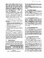
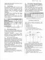
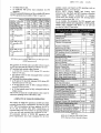
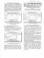
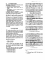
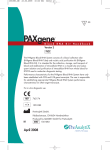
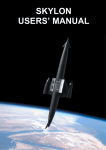
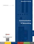
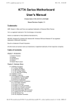
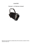
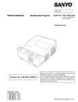
1122
IEPC-97-184
CONSTRAINTS ON ELECTRICAL POWER SYSTEM DESIGN FROM IPS OPERATION
L. Croci, P. Galantini, A. Trivulzio
FIAR S.p.A, Space Division - a Fiiccanica
company
Via Montefeltro, 8 - 20126 MILAN0 (I)
tel. (++39) (2) 35790.1 - fax (++39) (2) 33400981 - E-mail: [email protected]
H. Bassner
Daimler-Benz Aerospace AG, Space Infrastructure
Postfach 801168 - 81663 MUNICH, Germany
tel. (49)
(89) 60723126 - fax (++49) (89) 60725070
ABSTRACT
Ion Propulsion Systems (IPS), like the Radiofrequency
Ion Thrusters Assembly (RITA) from DASA, are now at
the threshold of application on commercial satellites and
appear to be a very attractive alternative to the chemical
propulsion systems to perform the North-South Station
Keeping (NSSK) manoeuvres of geostationary (GEO)
satellites as well as to perform orbit raising manouvres.
RITA IPSs are available in several configurations from
15 to 200 mN thrust levels and are characterised by a
large throttling capabilities to adjust the thrust level to
meet the optimum combination of operating time and
Electrical Power System (EPS) load during the different
mission phases.
Starting from the operational characteristics in terms of
electric power demand, daily switching cycle and
operating time of the different RITAs, the influence of
the relevant requirements over the electrical power
system (EPS) characteristics is evaluated, with particular
consideration for the energy source sizing.
A trade-off is carried out between the supply of the IPS
power demand at beginning of life either via the solar
generator or via the spacecraft batteries.
The increased number of battery charge/discharge cycles
is also considered versus battery expected lifetime,
battery charge rates and battery charge regulator
configuration.
Main bus protection and thermal dissipation constraints
are also discussed.
The results of the above trade-off is then summan‘sed in
defting the optimum configuration of an EPS sized to
supply a GE0 satellite equipped with an IPS with the
minimum overall mass. The specific design constraints
are also highlighted.
Plasma Thruster), RITAs, being characterised by a high
specific impulse (Isp), allow significant propellant mass
saving. Typical RITA advantages vs. arcject and SPT
electric propulsions are shown in Figure 1.1 where the
launch mass saving and the spacecraft (S/C) platform
capability improvements are reported in applications
where JPS is used for NSSK tasks in GE0 satellites.
Additional S/C dry mass capability increase is expected
to be gained replacing the apogee motor with ion
thrusters of some hundreds of mN thrust level coupled
a different
GE0
transfer
orbit
(e.g.
with
supersynchronous transfer orbits).
Am@ct SPT 100 RITA 10
EP Technology #or NSSK
~_r
Figure 1.1 - *ical
.dvantages of RZTA IPS
To meet commercial market requirements, four RITA
versions art available with thrust levels from 15 to 200
mN [Ref. 11.
RITAIPS
I
Kev Words: Electric Propulsion, IPS, Ion Propulsion,
RITA, EPS, NSSK, GE0 satellites
“0ao4050ao
rnfw
w
L-I
120
IAN)
140
16~
iao
zoo ”
MTA 10 WA 15 RITA la RITA 28 IS’S ME Power
-e-----c
-v-
1. INTRODUCTION
Ion thrusters require electric energy to operate. When
compared with the chemical systems or other electric
propulsion systems like the arcject and SPT (Stationary
I
I
1
Figure 1.2 - RITA Ion Propulsion Systems
One of the most interesting capability of the RITAs is the
throttling performance associated to high specific
Copyright 1997 by the Electric Rocket Propulsion Society. AU rights reserved.
IEPC-97:184
impulse: with this capability the thrust level can be
adjusted to meet the optimum combination of operating
time and EPS load constraints during the different
mission phases. Figure 1.2 provides the thrust level
capability and Elated overall Main Bus (MB) power
consumption of the planned RITA systems. Even if
primarily designed for commercial GE0 satellites, RlTA
lPSs can find application also in scientific, earth
observation and planetary missions.
However, IPS implementation
is not a simple
straightforward approach and requires accurate trade-off
on the different subsystems of the spacecraft to analyse
impacts and constraints. On the EPS, these constraints
are function of several parameters like satellite mass,
mission time, IPS thrust level and related power
consumption, thruster allocation and AOCS strategy,
needed to operate also during eclipse periods etc.
2. IPS OPERATIONAL
CHARACTERISTICS
IPS can be used on GE0 satellites to perform efficiently
several tasks:
l
autonomous and smooth NSSK manoeuvres, with
consequent improved antenna pointing accuracy, less
frequent ranging operations and easier collocation of
satellites;
l
efficient and fast satellite repositioning in orbit;
l
End-of-Life (EOL) de-orbiting;
l
orbit raising and final orbit circularisation with hybrid
propulsion (chemical plus IPS) or full ion
propulsion.;
l
East-West Station Keeping (EWSK) manoeuvres.
The first major application of lPS on GE0 spacecraft’s is
the replacement of chemical propulsion for NSSK tasks.
NSSK manoeuvres are performed to compensate the
required thrust velocity increment (47 m/s year) around
the orbit’s nodes that occur at 90” and 270” positions of
the orbit. Today the NSSK manoeuvres are executed
about every 70 days and manually controlled from the
ground staff. With IPS the NSSK manoeuvres are to be
executed once or two times per day and can be done
autonomously by the spacecraft itself.
.
Satellite Performances
GE0 satellites are growing in mass, installed electrical
power and mission lifetime as well. Table 2.1 provides
the four satellite categories that have been considered,
representing the largest GE0 satellites market expected
in the future.
Satellite Cat. 1 Cat. 2 Cat. 3 Cat. 4
BOLMassF
]
1,500 2,000 2500
3,000
Launch Mass k ]
2,430 3,240 4,050 4,840
EOL MB Power [w][l]
3,000 6,000 8,000 12,000
Mission
Tie
[
r.]
15
cc
Overall minimum MB Power (P/L power + SM power + Batteries
Charge power)
Table 2.1- GE0 Satellite Main Pelfomances
1123
The launch masses reported assume chemical propulsion
for apogee injection into GE0 orbit from geostationary
transfer orbit @TO).
A Fully regulated EPS, i.e. Main Bus (MB) voltage kept
constant in both sunlight and eclipse conditions, has been
considered.
2.2
IUTA Thrusters Allocation
The ion thrusters for NSSK tasks can be allocated in the
Anti-Earth configuration or in the more simple and
efficient E/W configuration [Ref. 11.
The Anti-Earth allocation is easily adaptable to existing
S/C’s platforms while the JYW allocation is
recommended for the platforms conceived for lPS
operation since the beginning.
2.2.1
Anti-Earth accomodation for NSSK
In the Anti-Earth configuration the thrusters are to be
mounted on gimbals for alignment towards the
spacecraft’s COG (Centre of Gravity); canting angle
depends on satellite geometry, 45” towards N-S axis is a
standard. A North thrust firing (at 90”) has to be followed
by a South thruster firing (at 2700), in order to cancel the
effects of the radial component of the thrust (eccentricity
impact). Therefore the NSSK manoeuvre has to be
executed twice a day with a constant period of 12 hours
or every 36 hours.
East-West accomodation for NSSK
2.2.2
In the E/W configuration the thrusters are to be operated
in pair. No radial component have to be compensated,
and only one firing per day can be done (North or South
thrusters) but duration has to be doubled with respect to
two operations per day. Therefore the NSSK manoeuvre
is executed once a day but with a constant period of 24
hours or twice a day with a constant period of 12 hours.
The canting angle versus the N/S-axis can be decreased
to 3Y.
Allocation for NSSK and Orbit Raising
2.2.3
Two possibility exists:
l
separate and different thrusters for the two tasks, or
l
single thruster for combined tasks.
ln the Anti-Earth approach, mounting the thrusters on
gimbals with large pointing capability makes possible to
change the thrusters position to perform orbit raising or
NSSK manoeuvres.
For orbit raising, two or four thrusters have to be
operated, depending on the power available; inclination
with respect to the flight direction could be 10”. The
payload is off during this phase and all power is availabe
to feed the IPS.
For NSSK manoeuvres, the thrusters will be brought into
a position where the thrust vector pass through the COG
of the satellite. One thruster is operated at a time, at
reduced thrust level, if there are limitation on available
power for IPS operation. The increased thrust available
by operating two thrusters at the same time can be
IEPC-97-184
usefully utilised during satellite repositioning, being the
payload off during this phase.
AOCS Operation
IPS is normally operated
2.3
daily but time for orbit
determination has to be allowed. A seven days AOCS
cycle has been considered e.g. N/S correction every day
except for the 7th day, dedicated to the orbit
determination. Table 2.3.1 provides the IPS operating
requirements
for
the
two
thrusters
allocation
arrangements.
Longer sailing time, e.g. 14 or 28 days cycles, increases
the number of IPS operating days, thus slightly
increasing the system efficiency.
EWSK manoeuvres are still operated with chemical
thrusters; operation of lPS and chemical systems cannot
be done contemporary.
1124
2.6
RITA Selection Vs Spacecraft Performances
Based on the spacecraft’s performances identified in
Table 2.1, the best application of the different RlTA
versions is provided in Table 2.6.1.
However, final selection has to be based on Customer
trade-off since optimum solution from a technical point
of view could be commercially less attractive when
benefits from commonalities among the production are
taken into consideration or, last but not least, lifetime
demonstration required time is evaluated [Ref. 11.
l’able 2.6.1
RITA Applications Vs Spacecraf Per$ormances
3. EPS SIZING WITHOUT IPS
Table 2.3.1 - IPS Operating Constraints
2.4
RITA Redundancy Scheme
Due to the beam grid geometry adopted and the use of a
RF-field for the propellant ionisation, the RIT thrusters
are characterised by a lifetime in excess of 20,000 hours
for all versions of thrust levels.
Consequently,
considering
a minimum
lifetime
qualification factor of 1.3, all mission requirements can
be. met with a 2+2 thrusters redundancy scheme in both
Anti-Earth and EtW configurations.
2.5
RITA Operation During Jklipses
NSSK manoeuvres never take place during eclipses so
that the solar array can always be used to power, at least
partially, the RITA. In particular, the nodes for NSSK
manoeuvres are six hours after or before eclipses.
In the past, IPS operation during eclipse seasons (1.2
hours for 84 days a year) was avoided due to the
maximum allowable battery stress and the large EPS
oversize required to feed the IPS
The ever increase of today GE0 satellite performances
and the replacement of NiCd batteries with NiH2 type has
resulted in:
l
increased available on-board power,
. increased allowable batteries stress,
and, therefore, new trade-offs have to be performed to
quantify the impacts on EPS sizing if lPS has to be
operated also during eclipses.
Figure 3.1 shows a simplified block diagram of a fully
regulated EPS. The following efficiencies/losses have
been considered:
Sk efficiency: 97%
BCR efficiency: 90%
BDR efficiency: 93%
Ll - losses between S3R and SA: 3%
L2 - losses between BCR/BDR and batteries: 2%
K factor (battery charge rate efficiency coefficient):
1.05
Ll
MRU
_
Main&Is
1
SA
IFigure 3. I - EPS Block Diagram
The EOL SA power at Summer Solstice (SS) represents
the minimum SA available power but the worst case for
EPS sizing is represented by the Spring (Vernal) Equinox
(VE) conditions when the SA must provide the power
also to recharge the batteries.
Therefore the EPS has been first sized at VE with the
following constraints:
l
energy in eclipses provided by two batteries,
l
75% nominal Batteries Depth of Discharge (DOD),
l
parallel batteries charge, charge rate C/15,
l
possibility to sequential batteries charge, charge rate
c/10,
IEPC-97-184
SA fitted with Si cells,
no additional MB power load considered for IPS
operation.
The EPS main performances and the available MB power
for lPS operation are provided in Table 3.1 and 3.2.
l
l
Satellite
MB Pm + PSM(w)
MBPBC
(w)
TotalMBpwrCW)
Battery En. (Wh)
EOL SA pwr (W)
-VB
- ss
BOL SA pwr (w)
-VB
- ss
BOL MB pwr for
IPS operation (w)
-VB
-
ss
BOL MB pwr for
IPS operation (w)
- VE
- ss
~,&~,~:
10,860
1,140
12,000
19,064
15,664
15,269
Thrust Level
1,140
838
3.878
3,507
B’S operation for NSSK tasks is possible without impacts
on EPS provided that the following conditions are met:
ZPS operated only outside eclipse seasons
l
satellites classes and based on IPS operating cycle as
described in 9 2.2.1.2.2.2 and 2.2.3.
RlTA’s PSCU (Power Supply and Control Unit)
electronics for Anti-Barth and FYW thrusters allocation
require slightly different architectures to minimise
overall mass and number of boxes still meeting failure
tolerance requirements [Ref. 1,2]:
As an example, the parameters for IPS operated only
outside eclipse seasons and computed for a 2000 kg BOL
satellite mass equipped with RlTA 10, 25 mN are
provided in Table 4.1 here below.
12,754
12,433
EPS Sizing and available MB Powerfor IPS Operation
(NSSK manoeuvres)
l
1125
at SS the EOL batteries DOD during IPS operation
must be 75% max.;
the batteries must be fully recharged before a second
lPS fmng occurs.
0
Canting Angle
45
z,‘,“: ,,:,
Spacecraft(S/C)D~~ai“,
,‘,:,$:<:‘: : .;+;:!:,
S/C Mass in GTO
kg
3240
S/C Mass in GE0 (BOL)
kg
2000
Mission Lifetime
years
15
EOL VE Overall MB Power
W
6000
C/IT
Battery Charee Rate
-. __
MBPIL- t SM Power
I w
1
5430
571)
MB Power for Batten, Charge
I w
I
Min. Battery Energy (for DOD 75%) 1 wh 1
- _
9532
h-417
I w
I
EOL Solar Arrav Power at VP
__.
I
I w
EOL Sob lr Arrav Power at SS
ZPS operated also during eclipse seasons
at SS and at VB the EOL batteries DOD during lPS
operation must be 75% max.:
at SS the batteries must be fully recharged before. a
second lPS firing occurs;
at VB the batteries must be fully recharged before an
eclipse occurs,
and last but not least the overall batteries stress must be
within the operating limits of the battery cells.
4. IMPACTS OF NSSK IPS OPERATION
The impacts of NSSK lPS operation on BPS have been
evaluated for the RlTA configurations provided in Table
2.6.1; B/W accomodation has been analysed for RITA
10, 15 and 18 systems only, after considerations on
available MB power versus number of operating thrusters
at the same time and operating time constraints as well.
All parameters relevant to NSSK IPS operation and
power requirements have been computed for the four
<cquircd Manoeuvre Duration
hours 1
3.19
I
> ..r
. _
~uanncarton racror
1.5
I
I
tequired Thruster Life Qualification ( hours 1
17290
<OL PO%&. &+&&e&
@f+G I.p:” : ,“:,,;,;-,,l~~~,r.i
;‘“::..:i
dB Power Available fm IPS
I
w
..
I
,
1
LB Pwr to be r_ _ ____ _, _________,
1 Wh
dB Energy from Batteries for lPS
{at&es DOD durin ,___
TPS nn~ratinn
_r ___._-.. 1 4/n
I” 1
Table 4.1
RITA IO, 25 mNfor GE0 NSSK Tasks
RITA Operated Only Outside Eclipses
&ICI
d, 1
1309
12 72
._1.,d
IEPC-97-184
4.1
1126
RITA Operated Only Outside JMipses
From a SA sizing point of view, all RITA confqgumtions
evaluated can be handled by the EPS without any
additional requirement in terms of electrical power or
energy to be provided, if RITA is operated only outside
eclipses, i.e. for 241 days/year. The batteries DOD at
EOL is within the 13 to 33 % range. A C/15 batteries
charge rate provides mom than 10% margin to achieve
full batteries charge before another manoeuvre has to be
executed. A typical batteries charge profile is shown in
Figure 4.1.1.
Zoo0 kg BOL, 15 Years Mission,C/15 Satteq Charge Rate
IPS Operated Only Outside Edipoes (241 days/year)
adjusting thrust level, if rcque&d
1
t
$%O
Figure 4.1.1 - Typical EOL Battery Charge Profile
During RITA Operation Outside Eclipses
(E/W Configuration)
4.2
RITA Operated Also During Eclipses
Anti-Easih Thrusters Allocations
All RITAs can be operated also during eclipses without
any SA EOL power increase, with exception of Category
1 spacecraft were a 115 W SA increase is required.
A typical batteries charge profile during eclipses is
shown in Figure 4.2.1.
1500 kg SOL. 15 Years Mission
Figure 4.2.1 - Typical EOL battery cycles during eclipse
seosons (Anti-Eatth Contguration)
B/W Thrusters Allocations (RITA IO, IS and I8 only)
A slightly increase in the EOL SA power at VE is
required as per Table 4.2.1 to operate the system also
during eclipses. A typical batteries charge profile during
eclipses for E/W thrusters allocation is shown in Figure
4.2.2.
power is not available
Table 4.2.1
Additional EOL SA Power Required with E/W Thrusters
Allocation for RKA Operation Also During Eclipses
1500 kg SOL. 15 Years Mission
IPS Operated Also During Eclipses (313 days/year)
44
Figure 4.2.2 - Typical EOL battery cycles during eclipse
seasons (E/W Configuration)
_
4.3
IUTA Operated for Orbit Raising Tasks
IPS application for orbit raising manoeuvres can be
considered to save additional mass. If thrusters are
dedicated to this task they can be mounted in fixed
position and aligned versus the flight direction, or can be
placed on gimbals to be used for both orbit raising and
NSSK tasks. To avoid disturbances to the spacecraft, the
thrusters have to be operated in pair(s).
The high thrust level stability, the tine thrust level
adjustment capability and the large throttling range
associated to a high specific impulse make RITAs a
suitable candidate for this tasks.
The S/C’s payload is normally off in this phase of the
mission, thermal connol has to be active to keep the
equipmet within minimum temperature range and the IPS
must be operated during sunlight conditions only and
switched-off as soon as the satellite is entering into
eclipse, being the batteries utilised for thermal control
purpose only during this phase.
Assuming that the required MB power is available, up to
four thusters can be contemporary operated achieving up
to a nominal thrust of 320 mN for RITA 18 and 800 mN
for RlTA 26 system; 70/100 V MB voltages are
recommended for this application. The throttling
capability of RITAs allow thrust level reduction,
increasing the time required to performed the task, in
case EPS constraints
impose less IPS power
consumption. In case of one thruster failure at beginning
of mission, only two thrusters are stil available to
perform the task.
IEPC-97-184
4.4
EPS Archim
Impacts
The following constraints have to be taken into account
in selecting the EPS architecture:
all SA-power has to be delivered to the MB;
sequential batteries charge strategy should be
avoided
Main Regulation Unit (MRU) dissipation increases
during sunlight operation;
high power loads switch on/off response.
No batteries charge via dedicated SA sections
architecture has to be selected, being SA power dedicated
to battery charge to be used also for IPS operation.
Sequential batteries charge strategy in case of BCR
failure imposes a complicated batteries management and
therefore has to be avoided. Consequently, redundancy of
BCR functions have to be implemented. This approach is
already common on several EPS; if not, about 2 kg BPS
mass increase has to be taken into account. Anyhow, in
case of emergency conditions the IPS can be switchedoff and sequential batteries charge can be performed.
During sunlight conditions some power has to be
provided by the batteries for II’S operation during NSSK
manoeuvres. Therefore, the MRU must be able to operate
when power is provided by both S3R and BDR functions,
with consequent increased unit dissipation. For better
EPS and IPS optimisation a single bus EPS is highly
recommended.
5. BATTERY STRESS
RITA operation places additional stress and increased
cycles on the batteries. This demand, which is repetitive
over the life of the mission, imposes peak power
requirements which will necessitate battery discharge
during both sunlight and eclipse periods.
The maximum stress is obviously reached at EOL, when
the power available from the SA is reaching the
minimum In order to maintain the batteries stress within
the limits it could be necessary to increase the SA size.
The expected NiHs batteries cycles are function of the
DOD [Ref. 31. For 3 1% electrolyte concentration, the
following cycles are expected:
l
70,000 for 30% DOD;
l
25,000 for 60% DOD;
l
9,ooO for 90% DOD.
In order to evaluate the overall batteries stress, the
accumulated cycles x DOD over the lifetime is assumed
not to exceed the value of 450,000 (a factor of 2 margin
from a maximum of 900,000 “cycles x DOD” achievable
with 90% DOD).
For 15 years mission time the worst case computed
overall batteries stress expressed as cyc1e.rx DOD are:
l
002,000 for SIC Category 1;
l
<236,000 for SIC Category 2;
l
<193,000 for S/C Category 3;
l
<133,000 for S/C Category 4.
1127
On the above basis, the combined batteries stress due to
eclipses and RITA operation are well within the
allowable value and enough margin is available for the
increased satellite in-orbit lifetime (e.g. 20 years).
Therefore, no increase of the SA size has to be
considered for IT’S operaton due to battery stress
requirement. However, to achieve these performances,
the guidelines mcomme&d by batteries manufacturers
and, in particular, the optimum Charge and Discharge
cycles operating temperatures have to be followed.
6.
SOLAR ARRAY DEGRADATION
The embarkment of IPS can produce additional power
constraints on the SA due to:
l
additional SA degradation due to the ion beam;
l
additional SA degradation during transfer orbit
manoeuvres due to the longer duration with respect to
chemical propulsion.
RITAs, as all gridded thrusters, are characterised by a
low beam divergency (>90% of the energy concentrated
into *12” beam width). Considering a minimum canting
angle of 35” mspect to N/S axis, the evaluated additional
solar array degradation is expected to be less than 1% for
a 15 year mission, As concerns SA degradation due to
longer permanence into low/medium orbits if orbit
raising and final allocation manoeuvres are performed by
IPS, the relevant amount is function of the selected
transfer orbit and thrust level available to perform the
orbit raising. Use of GaAs solar cells, which are more
tolerant to radiations, reduce the impacts.
7. MB TRANSIENTS RESPONSE
IPS on/off switching generates a very large load variation
to the MB; this variation can cause the MB to go outside
specified variation range, if not properly addressed in the
design of the EPS or in the IPS implementation.
In case of NSSK tasks, the power load variation can be in
the order of 1.5-3 kW depending on the nominal thrust
level and number of thrusters to be switched at the same
time. In case of use of IPS for orbit raising, the value is
much higher and can be in the order of 8-10 kW.
RITAs have been designed to avoid large power load
variations. In fact, a soft start-up is implemented and
moreover it is possible to mitigate the MB load variations
using the throttling capability function. All these
operating modes are executed automatically by the PSCU
of the thruster upon receipt of the on/off command or can
be commnaded from ground.
8. MB PROTECTION
To protect the MB from short circuits two alternatives
exists:
l
fuses
* EF (Electronic Fuses) or SSPC (Solid State Power
Controllers)
IEPC-97-184
Fuse protection is very popular, being very cheap, but
high margin from nominal to actual value have to be
taken and a MB voltage drop of some tens of ms have to
be accepted before a fuse blow.
Considering the in-rush current and the required derating
rules of the different devices, fuses can be used
efficiently for loads up to 15 A nominal.
With a 50 V MB, the nominal IPS MB current is in the
range of 11.6 to 16 A for the RITA 10 versions, 31 A for
RITA 15 and SOA for the RITA 18.
Therefore, fuses can be considered only for the RIT’A 10
version while EF or SSPC are mandatory for RITA 15
and RITA 18, unless specific design architectures are
implemented in the IPS electronics [Ref. 21.
EF or SSPC complexity are almost proportional to the
rated current and therefore power dissipation and cost of
a 32 A device is near twice the value of a 16 A device.
In case of higher MB voltage i.e. 100 V, fuses are the
favourite choice for all RlTAs.
9. EPS THERMAL ASPECTS
IPS implementation requires additional S/C heat rejection
capability due to:
l
dissipated power due to IPS;
l
additional dissipated power in the EPS.
In fact, the MRU has to provide the additional power
required by the IPS via SA and batteries when IPS is
used for NSSK tasks.
Figure 9.1 shows tbe power dissipated by the RITA and
the additional power to be dissipated by the MRU as
consequence of RITA operation. To reduce the MRU
thermal constraints when RlTA 18 or RITA 26 are
implemented, the thrust level can be reduced increasing
tbe IPS operating time.
Figure 9.1
Addirional S/C Thermal Rejection Requirements
For orbit raising tasks, IPS is always operated via SA and
therefore no additional constraints on MRU apply during
this mission phase.
10.ESD CONSTRAINTS
Electromagnetic
interactions between plasma
satellite structure occurs if charged ions arc emitted.
and
1128
No additional precautions have to be taken with RITAs,
since very few charged ions are emitted by the thruster,
as measured and the flight test data from the EURECA
experiment.
11. RITA ADVANTAGES
To compare RITA versus other ion propulsion concepts,
a design exercise similar to the one described before has
been performed considering an IPS malised with SPT
100 thrusters whose main perfomrances are summarised
in Table 11.1.
; :“il;u~~,~~~.~~~~~~,~~~:
,:.i:l;:~,:j:~~~~,.~~~~:~~~,~~~~~~;
y,c
Thrust Level 111
12 mN
Isp
1560 s
Beam Divergence
G5”
IPS required power
1555 w
Expected thruster lifetime
~7,000 hours
[I] 80 mN nominal, corrected for beam divergence
Table II.1 - SPT 100 IPS Main Petionnances
Comparing the results, the RITA systems provides the
following advantages:
in spite of tbe lower thrust to power consumption
ratio with respect to SPT technology, no penalizations
on EPS sizing is caused by RITA;
the low beam divergence allows both Anti-Earth and
E/W thrusters allocations with canting angle as low as
35” for RITA but not for SPT 100;
RITA 10 requires only one half of tbe heat rejection
capability increase compared to SPT 100, RITA 15 is
similar to SPT 100;
RITA does not generate ESD problems: very few
charged ions are emitted and therefore no particular
filters to decouple RITA’s PSCU and thruster are
required. On the contrary. due to the special
ionisation process and to the open extraction area,
SPT emits ions with different exhaust velocities and
filters have to be inserted to avoid conducted
susceptibility problems [Ref. 4, 51. The filter losses
have not been considered in the SPT required power
consumption indicated here above;
RITA’s soft start-up reduces power loads variations.
With SPT, the MB load variation at switch-on is even
amplified because 50% more power is required by
SIT for some millisenconds with respect to normal
power);
the RITA large throttling capability associated to high
specific impulse allows optimum combination of
power consumption and operating time ratio;
The RITA low beam divergence has negligible
impacts on SA degradation. Recent data on SPT 100
thrusters indicates serious problem if 45” canting
angle is used, due to direct impingement of the plume
on the SA in certain orbital conditions [Ref. 5, 61. If
IEPC-97-184
l
cW
a large canting angle has to be
implemented with reduced benefits from tbe high
thrust level;
RITA long thruster lifetime: >20,000 hours expected.
12. SUMMARY
Today GE0 commercial spacecraft can be equipped with
RITA IPS operating also during the eclipse seasons
without impacts in mrms of EPS energy source sizing,
thanks to the increased available on-board electrical
power with respect to previous spacecraft’sgenerations
and due to availability of NiHr batteries.
A combined assembly for NSSK manoeuvres and orbit
raising tasks is possible, accomodating the thrusters on
gimbals with high regulation angle, adjusting the thrust
level according to the satellite mission phase if MB
power constraints exists.
Use of fuses for MB protection from short-circuits is
possible in most of the cases, even if more sophisticated
(and costly) EF or SSPC devices offers best
performances in terms of protection and MB transients.
The soft start-up implemented in the RITA power
electronics generates a smooth MB voltage transient due
to RITA on/off switching. No particular measures due to
ESD phenomena have to be considered for RITA
systems.
The critical aspect of IPS implementation is represented
by the additional S/C thermal rejection capability
requested and in particular, the requirement for the MRU
to provide contemporary power from SA and batteries. In
case the IPS is implemented to reduce launch mass, this
aspect has to be investigated with the available S/C
thermal rejection margins at Winter Solstice. In case IPS
is implemented to allow embarkment of more complex
payload without increasing the launch mass, the available
S/C capability increase is used partially to increase the
payload performances and the rest to increase electric
power availability and thermal rejection capability. In
any case, to perform NSSK tasks, the selection of long
life gridded ion thrusters like the RITA 10 systems
reduces the additional power to be dissipated by the
MRU.
References
1. H.
Trivulzio:
Bassner,
K.
Bohnhoff,
A.
Commercialized Ion Propulsion For North/South
Station Keeping Of Communication Satellites - 25th
IEPC, 1997, Cleveland, Ohio
2. S. Arcisto, M. Gambarara, A Garutti, A. Trivulzio, A.
Truffi, H. Bassner, H. Mtiller: Power Supply And
Control Unit (PSCU) For Radio Frequency Ion
Thrusters (RIT) - 2nd European Spacecraft Propulsion
1997, ESTEC,
Conference,
Noordwjik,
The
Netherlands
3. NiHz User Manual - Eagle-Picher Industries
1129
4. B. Thi&, G. Beaufi, H. De&q: SPT Electrical
Module Development - 2nd European Spacecraft
Propulsion Confenncc, 1997, ESTEC, Noordwjik,
The Nethe&&
5. M. P. Burgasov et. al.: The Results Of Complex Work
Concerning The Problem Of Electric-Rocket Thrusters
Integration With Spacecd And Its Subsystems - 2nd
European Spaacraft Propulsion Conference, 1997,
ESTEC, Noordwjik, The Netherlad
6. J-F. Rousael, J. Bernatd: Numerical Simulation Of
ILNhl&En viromnent, Sputtering And Contamination
Of Satellite Due To Electric Propulsion - 2nd
European Spaaxraft Repulsion Conference, 1997,
ESTEC, Noordwjik, The Netherlands