1
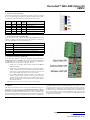
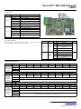
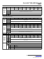
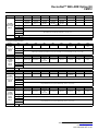
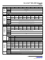
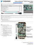
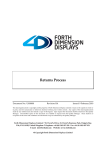
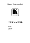
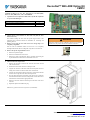
DeviceNet™ With ADR Option Kit
CM012
Applicable products: F7U, G7U, P7U, G5M (Spec F), and G5M (600V)
drives. For G5U (HHP) drives, refer to IG.G5HHP.16.
1. Unpack the DeviceNet Option Kit CM012 and verify that all components
are present and undamaged.
DeviceNet Option Kit CM012 Parts
Qty.
DeviceNet Option Card (UTC000180)
1
Installation Guide (IG.AFD.16)
1
2. Connect power to the Yaskawa AC drive and verify that the drive
functions correctly.
This includes running the drive from the operator keypad. Refer to the
appropriate drive technical manual for information on connecting and
operating the drive.
3. Remove power from the drive and wait for the charge lamp to be
completely extinguished.
WARNING
Dangerous voltages in excess of 400VDC (230V drives) or 800VDC
(460V drives) are present at the DC bus terminals of the drive.
Wait at least five additional minutes for the drive to be completely
discharged. Measure the DC bus voltage and verify that it is at a safe level.
4. Remove the operator keypad and drive cover.
a.
Remove the operator keypad.
b. Remove the terminal and control covers.
c.
Remove the option card hold-down plug by carefully compressing the
top and bottom until it becomes free of its holder. Lift it out.
Option card
hold-down plug
5. Mount the DeviceNet Option Card.
a.
Remove the DeviceNet connector and attach the DeviceNet network
cable as shown below.
b. Reconnect the DeviceNet connector to the Option Card.
c.
Align the J2 connector on the back of the DeviceNet Option Card to its
mating 2CN connector on the front of the drive control board.
d. Align the two stand-offs on the front of the drive control board with the
two holes on the right side of the DeviceNet Option Card.
e.
Press the DeviceNet Option Card firmly onto the drive 2CN connector
and stand-offs until the J2 connector is fully seated on 2CN and the drive
stand-offs have locked into their appropriate holes.
f.
Route the DeviceNet network cable along the left inside of the drive
enclosure.
g. Replace the Option Card hold-down plug.
Note: Do not ground the DeviceNet Option Card (UTC000180).
Yaskawa Electric America, Inc. – www.yaskawa.com
IG.AFD.16, Page 1 of 7
Date: 06/15/2007 Rev: 07-06
DeviceNet™ With ADR Option Kit
CM012
6. DeviceNet Network Connection
Connect the DeviceNet cable to the connector as shown. If the drive is the last
device on a network segment, make sure to install the terminating resistor (120Ω,
1%, metal film, 1/4W) between the CAN terminals 2 (blue) and 4 (white).
Name
Wire
Color
Black
V-
Black
Network Common
Blue
CAN_L
Blue
CAN Data Low
Green
Shield
Green
Cable Shield
White
CAN_H
White
CAN Data High
Red
V+
Red
Terminal
Color
1
2
3
4
5
Description
+24VDC
7. Set the DeviceNet Option Card Baud Rate
Set the drive baud rate by selecting the appropriate Baud Rate SW setting.
Settings of 3 through 8 will load the previously stored baud rate. A setting of 9
will enable Auto Sense. The factory default setting is 3.
Setting
Description
0
125 kbps
1
250 kbps
2
500 kbps
3~8
9
NVRAM (last stored baud rate) (3 = default setting)
Auto Sense
8. Set the DeviceNet Option Card MAC ID
Set the drive MAC address by selecting the appropriate settings of the address
MSD and LSD switches. The MSD switch sets the MAC address tens digit while
the LSD switch sets the ones digit. Valid MAC addresses are 0 through 63
although addresses of 0, 1, 62, and 63 are typically reserved.
•
Settings of 0 ~ 63: The MAC address will be selected from the MSD &
LSD switch settings.
•
Settings of 64 ~ 99: The MAC address will be set to the last saved MAC
address. The CM012 kit comes from the factory with the MAC address
switches set to 63 and the MAC address last saved to 63 (for use with
some vendor's faulted or automatic device recovery features).
•
For use with ADR-enabled controllers/scanners, power off the drive
and set the MAC ID rotary switches to 63. Power cycle the drive ON
and OFF. Change the MAC ID rotary switch setting to 64. Power the
drive ON. The MAC ID will be set at 63 and will be resettable through
the DeviceNet network.
Note: The drive's power must be cycled to accept new switch settings.
9. EDS Files
EDS files can be obtained from the CD that was included with the drive or
downloaded from www.yaskawa.com. Select Downloads, By Inverter Drives,
By Product, and Network Comms-DeviceNet. Then select the appropriate EDS
file based on the option kit and drive series and the latest version from those
listed. EDS files for individual drive models are compressed into a single Zip file
and need to be unzipped into a temporary directory in order to be installed. It is
recommended that the EDS file be downloaded from www.yaskawa.com to be
sure that the latest version is used. Install the EDS file into the DeviceNet
configuration tool (i.e., RSNetworx for DeviceNet). There is a separate EDS file
for each drive model. Verify that the correct EDS file has been installed for the
drive model configured. Refer to the documentation that came with the
DeviceNet master configuration tool for information on installing EDS files and
configuring a DeviceNet node.
Yaskawa Electric America, Inc. – www.yaskawa.com
IG.AFD.16, Page 2 of 7
Date: 06/15/2007 Rev: 07-06
DeviceNet™ With ADR Option Kit
CM012
10. LED Status
LED
MOD
NET
State
Indication
Off
No Power
On Green
Device Operational
Flash Green
Device in Standby
Flash Red
Minor Fault
On Red
Unrecoverable Fault
Flash Red-Green
Device Self-Test
Off
Not Powered/Not On-line
Flash Green
On-Line/Not Connected
On Green
Link OK/On-Line and Connected
Flash Red
Connection Time-Out
On Red
Critical Link Failure
Flash Red &
Green
Communication Faulted
11. Set Drive Parameters
Set drive parameters b1-01 and b1-02 to their appropriate values. Refer to the
table to the right for available b1-01 and b1-02 values.
Parameter
b1-01
b1-02
Function
Reference
Source
Run
Command
Source
Data
Description
0
Digital Operator
Default
1
Terminal Strip
2
Built-in Modbus RTU RS-485
Terminals
3
Option Kit (DeviceNet Option)
4
Pulse Input (F7 and G7 Only)
0
Digital Operator
1
Terminal Strip
2
Built-in Modbus RTU RS-485
Terminals
3
Option Kit (DeviceNet Option)
1
1
12. Supported Input Instances
Instance
20 (14h)
Basic Speed
Control
4 Bytes
22 (16h)
Basic Speed
and Torque
Control
6 Bytes
Bit 6
Bit 5
Bit 4
Bit 3
Bit 2
Bit 1
Bit 0
–
–
–
–
–
Fault Reset
–
Run Forward
Reserved
2
Speed Reference (Scaled by Parameter o1-03) (U1-01)
3
Byte
21 (15h)
Extended
Speed
Control
4 Bytes
Instance
Bit 7
0
1
Instance
Note:
Byte
0
Bit 7
Bit 6
Bit 5
Bit 4
Bit 3
Bit 2
Bit 1
Bit 0
–
Network
Reference1
Network Run
Command1
–
–
Fault Reset
Run Reverse
Run Forward
1
Reserved
2
Speed Reference (Scaled by Parameter o1-03) (U1-01)
3
1
Not available for G5
Byte
Bit 7
Bit 6
Bit 5
Bit 4
Bit 3
Bit 2
Bit 1
Bit 0
0
–
–
–
–
–
Fault Reset
–
Run Forward
1
2
3
4
5
Reserved
Speed Reference (Scaled by Parameter o1-03) (U1-01)
Torque Reference (0.1%) (FVC Mode Only, A1-02 = 3) (U1-09)
Yaskawa Electric America, Inc. – www.yaskawa.com
IG.AFD.16, Page 3 of 7
Date: 06/15/2007 Rev: 07-06
DeviceNet™ With ADR Option Kit
CM012
Instance
Byte
Bit 7
0
23 (17h)
Extended
Speed and
Torque
Control
6 Bytes
–
Bit 6
Bit 5
Bit 4
Bit 3
Bit 2
Bit 1
Bit 0
Network
Reference1
Network
Run
Command1
–
–
Fault Reset
Run Reverse
Run Forward
Bit 1
Bit 0
1
Reserved
2
Speed Reference (Scaled by Parameter o1-03) (U1-01)
3
4
Torque Reference (0.1%) (FVC Mode Only, A1-02 = 3) (U1-09)
5
Note:
1
Not available for G5
13. Yaskawa Supported Input Instances
Instance
Byte
Bit 7
0
100 (64h)
Modbus
Message
5 Bytes
Bit 6
Bit 5
Bit 4
1
3
Data
Refer to output assembly instance 150 (96h) for response.
Instance
Byte
Bit 7
Bit 6
Bit 5
Bit 4
Bit 3
Bit 2
Bit 1
Bit 0
0
Terminal S81
Terminal S7
Terminal S6
Terminal S5
Terminal S4
Terminal S3
Terminal S2
Terminal S1
1
Terminal
M5-M6
Terminal
M3-M4
Terminal
M1-M2
–
–
–
Fault Reset
External Fault
2
101 (65h)
Standard
Control
8 Bytes
Speed Reference (Scaled by Parameter o1-03) (U1-01)
3
4
Torque Reference (0.1%) (FVC Mode Only, A1-02 = 3) (U1-09)
5
6
Torque Compensation (0.1%) (FVC Mode Only, A1-02 = 3)
7
Note:
1
Instance
105 (69h)
Enhanced
Control/
Modbus
Message
8 Bytes
Bit 2
Register Number
2
4
Note:
Bit 3
Function Code (Only Modbus functions register read (03h) and register write (10h) are supported)
G5, F7, and G7 Only
Bit 7
Bit 6
Bit 5
Bit 4
Bit 3
Bit 2
Bit 1
Bit 0
0
Byte
Terminal S81
Terminal S7
Terminal S6
Terminal S5
Terminal S4
Terminal S3
Terminal S2
Terminal S1
1
Terminal
M5-M6
Terminal
M3-M4
Terminal
M1-M2
–
Function Bit 22
Function Bit 12
Fault Reset
External Fault
2
Speed Reference (Scaled by Parameter o1-03) (U1-01)
3
4
Register Number
5
6
Data
7
Refer to output assembly instance 155 (9Bh) for response.
1
Notes:
2
G5, F7, and G7 Only
Bit 1
Bit 2
0
0
Function Description
No Function
0
1
Read Register
1
0
Write Register
1
1
No Function
Yaskawa Electric America, Inc. – www.yaskawa.com
IG.AFD.16, Page 4 of 7
Date: 06/15/2007 Rev: 07-06
DeviceNet™ With ADR Option Kit
CM012
Instance
107 (6Bh)
Standard DI/
DO Control
8 Bytes
Byte
Bit 7
Bit 6
Bit 5
Bit 4
Bit 3
Bit 2
Bit 1
Bit 0
0
Terminal S81
Terminal S7
Terminal S6
Terminal S5
Terminal S4
Terminal S3
Terminal S2
Terminal S1
1
–
–
Terminal S122
Terminal S112
Terminal S102
Terminal S92
Fault Reset
External Fault
2
Terminal
P4-C42
Terminal
P3-C32
Terminal
M5-M6
Terminal
M3-M4
Terminal
M1-M2
–
–
–
3
Reserved
4
Analog Output Terminal FM (Terminal 21 on G5) (-726 ~ +726 (-11VDC ~ +11VDC))
5
6
Speed Reference (Scaled by Parameter o1-03) (U1-01)
7
Notes:
1
G5, F7, and G7 Only
2
G7 only
14. Supported Output Instances
Instance
Byte
0
70 (46h)
Basic Speed
Control
4 Bytes
–
Bit 6
–
–
Bit 4
–
Byte
0
Bit 7
Speed Agree
0
Fault
Bit 5
Bit 4
Bit 3
Bit 2
Bit 1
Bit 0
Network
Reference1
Network
Run
Command1
Drive Ready
Running in
Reverse
Running
Forward
Alarm
Fault
Bit 7
–
Bit 6
–
Bit 5
–
Bit 4
–
1
Bit 2
Bit 1
Bit 0
–
Running
Forward
–
Fault
Motor Speed (Scaled by Parameter o1-03) (Not Available in V/F Control Mode, A1-02 = 0) (U1-05)
3
4
Torque Reference (0.1%) (FVC Mode Only, A1-02 = 3) (U1-09)
5
Byte
0
Bit 3
Reserved
2
Bit 7
Speed Agree
1
Bit 6
Bit 5
Bit 4
Bit 3
Bit 2
Bit 1
Bit 0
Network
Reference1
Network
Run
Command1
Drive Ready
Running in
Reverse
Running
Forward
Alarm
Fault
Reserved
2
Motor Speed (Scaled by Parameter o1-03) (Not Available in V/F Control Mode, A1-02 = 0) (U1-05)
3
4
Torque Reference (0.1%) (FVC Mode Only, A1-02 = 3) (U1-09)
5
1
–
Not available for G5
Byte
73 (49h)
Extended
Speed and
Torque
Control
6 Bytes
–
Motor Speed (Scaled by Parameter o1-03) (Not Available in V/F Control Mode, A1-02 = 0) (U1-05)
3
Instance
Bit 0
Reserved
2
72 (48h)
Basic Speed
and Torque
Control
6 Bytes
Bit 1
Bit 6
1
Instance
Bit 2
Running
Forward
Motor Speed (Scaled by Parameter o1-03) (Not Available in V/F Control Mode, A1-02 = 0) (U1-05)
3
1
Bit 3
Reserved
2
71 (47h)
Extended
Speed
Control
4 Bytes
Note:
Bit 5
1
Instance
Note:
Bit 7
Not available for G5
Yaskawa Electric America, Inc. – www.yaskawa.com
IG.AFD.16, Page 5 of 7
Date: 06/15/2007 Rev: 07-06
DeviceNet™ With ADR Option Kit
CM012
Instance
Byte
Bit 7
Bit 6
Bit 5
150 (96h)
Modbus
Message
5 Bytes
Bit 4
1
3
Bit 1
Bit 0
Bit 3
Bit 2
Bit 1
Bit 0
Zero Speed
Running
Forward
Power Loss
Ride Thru
OPE Error
Data
Refer to input assembly instance 100 (64h) for command.
1
Instance
A Modbus message error is returned if the function code has the MSB (bit 80h) set.
Byte
151 (97h)
Standard
Control
8 Bytes
Bit 7
Bit 6
Bit 5
0
Fault
Alarm
Drive Ready
Speed Agree
Fault Reset
1
Zero Servo
Complete1
–
Terminal
M5-M6
Terminal
M3-M4
Terminal
M1-M2
Local Mode
2
Output Frequency (Scaled by Parameter o1-03) (U1-02)
3
4
Torque Reference (0.1%) (FVC Mode Only, A1-02 = 3) (U1-09)
6
Output Current (0.01A or 0.1A, Based on Drive Capacity) (U1-03)
7
1
Instance
Flux Vector Control Mode Only (A1-02 = 3)
Byte
155 (9Bh)
Enhanced
Control/
Modbus
Message
8 Bytes
Bit 4
Running in
Reverse
5
Note:
Bit 2
Register Number
2
4
Notes:
Bit 3
Function Code1
0
Bit 7
Bit 6
Bit 5
Bit 4
Bit 3
Bit 2
Bit 1
Bit 0
Zero Speed
Running
Forward
Undervoltage
OPE Error
0
Fault
Alarm
Drive Ready
Speed Agree
Fault Reset
Running in
Reverse
1
Terminal
M5-M6
Terminal
M3-M4
Terminal
M1-M2
Local Mode
Function Bit
21
Function Bit
11
2
Output Frequency (Scaled by Parameter o1-03) (U1-02)
3
4
Register Number
5
6
Data
7
Refer to input assembly instance 105 (69h) for command.
Notes:
Instance
157 (9Dh)
Standard
DI/DO
Control
8 Bytes
Bit 1
Bit 2
0
0
None
0
1
Message Accepted
1
0
Message Error
1
1
Complete
1
Byte
Function Description
Bit 7
Bit 6
Bit 4
Bit 3
Bit 2
Bit 1
Bit 0
Zero Speed
Running
Forward
0
Fault
Alarm
Drive Ready
Speed Agree
Fault Reset
Running in
Reverse
1
Zero Servo
Complete3
–
–
–
–
Local Mode
Undervoltage
OPE Error
2
Terminal
S102
Terminal S92
Terminal S81
Terminal S7
Terminal S6
Terminal S5
Terminal S4
Terminal S3
3
Terminal
P4-C42
Terminal
P3-C32
Terminal
M5-M6
Terminal
M3-M4
Terminal
M1-M2
–
Terminal S122
Terminal S112
4
Analog Input Terminal A1 Monitor (Terminal 13 on G5) (0.1%) (U1-16)
5
6
Output Frequency (Scaled by Parameter o1-03) (U1-02)
7
Notes:
Bit 5
1
G5, F7, and G7 only
2
G7 Only
3
Flux Vector Control Mode Only (A1-02 = 3)
Yaskawa Electric America, Inc. – www.yaskawa.com
IG.AFD.16, Page 6 of 7
Date: 06/15/2007 Rev: 07-06
DeviceNet™ With ADR Option Kit
CM012
Copies of this Installation Guide along with all technical manuals in “.pdf” format and support files may be obtained from either the CD supplied with the drive or from
www.yaskawa.com. Printed copies of any Yaskawa manual may be obtained by contacting the nearest Yaskawa office. Information on DeviceNet may be obtained from
www.odva.org.
Reference Documents:
G5U Technical Manual - TM.4515
GPD515/G5 Modbus Technical Manual - TM.4025
F7U Drive User Manual - TM.F7.01
F7U Drive Programming Manual - TM.F7.02
F7U Drive Parameter Access Technical Manual - TM.F7.11
G7U Drive Technical Manual - TM.G7.01
G7U Drive Parameter Access Technical Manual - TM.G7.11
P7U Drive User Manual - TM.P7.01
P7U Drive Programming Manual - TM.P7.02
P7U Drive Parameter Access Technical Manual - TM.P7.11
DeviceNet Option Kit CM012 Technical Manual - TM.AFD.16
YASKAWA ELECTRIC AMERICA, INC.
Chicago-Corporate Headquarters
2121 Norman Drive South, Waukegan, IL 60085, U.S.A.
Phone: (800) YASKAWA (800-927-5292) Fax: (847) 887-7310
Internet: http://www.yaskawa.com
YASKAWA ELECTRIC CORPORATION
New Pier Takeshiba South Tower, 1-16-1, Kaigan, Minatoku, Tokyo, 105-0022, Japan
Phone: 81-3-5402-4511 Fax: 81-3-5402-4580
Internet: http://www.yaskawa.co.jp
YASKAWA ELECTRIC EUROPE GmbH
Am Kronberger Hang 2, 65824 Schwalbach, Germany
Phone: 49-6196-569-300 Fax: 49-6196-888-301
Data subject to change without notice
Yaskawa Electric America, Inc. – www.yaskawa.com
IG.AFD.16, Page 7 of 7
Date: 06/15/2007 Rev: 07-06