1
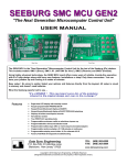
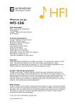
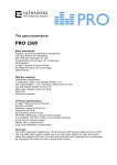
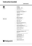
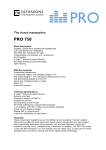
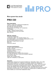
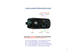
Invacare® REM A/B
Remote
Operating manual
1529173.doc - English
10.04.2012
REM A keypad
Notes on operating manual
This manual describes operation of your wheelchair using the REM A remote (without lighting), or the
REM B (with lighting). The basic functions of each model are the same. For reasons of legibility, the
author will use the name "remote" for the description of common functions if both models are being
referred to. The additional functions of the REM B will be described additionally at the appropriate
location.
Figures and explanations refer to standard settings made at the works. If you are using a remote
which has been configured for you personally, please contact your Invacare® dealer.
The remote is a component of the entire wheelchair. You should therefore read all manuals
supplied before using it for the first time!
Safety instructions!
It is imperative that you observe and follow the safety information!
Non-observance of these warnings can lead to serious injuries or death,
and to considerable damage to the wheelchair.
The term Programming used in this manual refers to parameter changes and configuration of the
remote software. Programming may only be carried out by authorised persons.
The term Accessories used in this manual refers to all devices additional to the remote main functions.
It does not refer to all accessories available for the wheelchair.
if the wheelchair is used improperly, or if unauthorised manipulation is made to the remote or at
electronic components, the manufacturer's guarantee ceases to apply and the manufacturer is
relieved of all liability.
2009
2
Displays and controls
Contents
1
2
3
Displays and controls ....................................................................................................................... 4
1.1
REM A keypad............................................................................................................................ 4
1.2
REM B keypad............................................................................................................................ 4
1.3
Joystick....................................................................................................................................... 5
1.4
Light sensor ................................................................................................................................ 5
1.5
Charging socket.......................................................................................................................... 5
Functions.......................................................................................................................................... 6
2.1
Switching on/off .......................................................................................................................... 6
2.2
Activate / deactivate the immobiliser .......................................................................................... 7
2.3
Driving ........................................................................................................................................ 7
2.4
The horn ..................................................................................................................................... 9
2.5
Seat adjustment........................................................................................................................ 10
2.6
Lighting REM B......................................................................................................................... 12
2.7
Display battery charging status ................................................................................................ 13
2.8
Service/fault display.................................................................................................................. 15
Maintenance/programming ............................................................................................................ 18
3.1
3
Drive program recovery ............................................................................................................ 18
REM B keypad
1 Displays and controls
1.1 REM A keypad
(1)
Display battery charging status
(2)
Display battery empty
(3)
Drive profile down
(4)
Horn
(5)
Light sensor
(6)
Display seat adjustment profile
(7)
Actuator select down
(8)
Display companion mode
(9)
Remote on/off
(10)
Display battery full
(11)
Drive profile up
(12)
Driving profile display
(13)
Immobiliser LED
(14)
Actuator select up
(15)
Service/fault display
1
9
2
10
3
11
4
12
5
13
6
14
7
15
8
1.2 REM B keypad
(16)
Display indicator left
(17)
Indicator left on/off
(18)
Hazard blinker on/off
(19)
Display indicator right
(20)
Indicator right on/off
(21)
Light on/off
(22)
Display light
16
19
17
20
21
18
22
4
Displays and controls
1.3 Joystick
The joystick function depends on the operating mode selected.
In drive mode, you drive the wheelchair using the joystick and regulate the speed.
In seat setting mode, you change the setting profile with the joystick and adjust the seat
components.
The black arrow on the figure symbolises the travel direction of the joystick as seen by the
driver.
1.4 Light sensor
The light sensor adapts the brightness of the display to the surrounding light conditions.
1.5 Charging socket
(23)
Charging socket
23
5
Switching on/off
2 Functions
2.1 Switching on/off
Switching on the remote
How to switch the remote on:
Note: The joystick must be in the neutral position (centre).
Press the on/off button.
All displays on the keypad illuminate briefly.
The wheelchair is ready to drive as long as the battery charging status and the driving
profile selected are displayed.
Joystick not in neutral position when switching on
If the remote is switched on when the joystick is not in the central position, the "not in neutral position"
stop will be set during booting. This function prevents the wheelchair driving off unintentionally.
How to recognise the "out of neutral position" stop:
All diodes on the driving profile display blink permanently.
The wheelchair does not move.
+
How to rectify the "out of neutral position" stop within the first 4 seconds:
Move the joystick to the neutral position.
The error has been rectified if the driving profile display is no longer blinking.
How to rectify the "out of neutral position" stop after the first 4 seconds:
Switch the remote off.
Switch the remote on again.
If the error has not been rectified, please contact your Invacare® dealer immediately.
Switching the remote off
How to switch the remote off:
Stop the wheelchair.
Press the on/off button.
All displays on the keypad go out.
The remote is switched off.
If the remote is switched off during a journey the wheelchair will carry out
emergency braking. The remote only switches off after this.
6
Functions
2.2 Activate / deactivate the immobiliser
You can use the drive immobiliser to prevent unauthorised people using the wheelchair.
Activate the immobiliser
Whilst the remote is switched on:
Press and hold the ON/OFF button (9) for 4 seconds.
The remote will switch off immediately. After 4 seconds the driving profile display and the
immobiliser LED will illuminate.
The immobiliser is activated.
Deactivate the immobiliser
Whilst the immobiliser is activated:
Switch on the remote using the ON/OFF button (9).
The immobiliser LED will illuminate.
Press the horn button (2) twice. You have about 10 seconds to do this.
The immobiliser is deactivated.
2.3 Driving
How to drive the wheelchair with the joystick:
Move the joystick in the direction in which you wish to travel.
The wheelchair starts to move.
You can now use the joystick to move your wheelchair
variably in any required direction. For reasons of clarity,
only four directions are shown in this manual.
forwards
to the right
backwards
to the left
7
Driving
The following applies to all joystick movements:
the further the joystick is moved away from the middle,
the quicker the wheelchair will drive or the quicker the
seat settings will change.
The further the joystick is moved in a particular direction,
the more dynamically the wheelchair reacts.
The G-Trac™ option
If your mobility device has been fitted with the G-Trac™ option, it will enable you to enjoy fatiguefree and safer driving.
• G-Trac™ supports you in staying at the same driving speed and travel direction, and therefore
reduces fatigue.
• It improves the tracking and therefore increases the user's driving comfort.
• G-Trac™ stabilises the mobility device tracking in the case of front-wheel-drive devices and
finds the optimum driving speed for travelling round bends. This prevents skidding, slipping or
tipping of the mobility device and therefore increases safety.
Driving profile
You can use the driving profile to adapt the top speed and dynamic behaviour of your wheelchair to
your personal requirements and the surroundings. You can select between up to 6 driving profiles.
The number of available profiles is dependent on how the control system is programmed. You can see
which driving profile has been set by looking at the driving profile display.
Your Invacare® dealer can configure the driving profile to match your personal requirements.
Display
Meaning
Driving profile 1
Driving profile 2
Driving profile 3
Driving profile 4
Driving profile 5
Driving profile 6/Attendant control mode
Please refer to Section 0 Attendant control mode (optional) on page 9.
8
Functions
Information for mobility devices with G-Trac™
If your mobility device has been fitted with the G-Trac™ option you will NOT be able to change
driving profiles while travelling.
How to select a driving profile:
Press the "Drive profile up" button.
The next driving profile is active.
Press the "Drive profile down" button.
The previous driving profile is active.
Attendant control mode (optional)
The attendant control mode becomes active as soon as an attendant remote is
switched to the "attendant control" function.
The attendant control display illuminates.
The REM A/B joystick is deactivated.
The attendant control mode driving profile cannot be changed.
All other functions are retained.
If you change to the seat setting mode, attendant control mode will be cancelled.
For more information, please read Section Seat adjustment from page 10.
2.4 The horn
How to use the horn:
Press the horn button.
The horn will sound fur as long as you keep the button pressed.
9
Seat adjustment
2.5 Seat adjustment
The adjustment facilities described in this section are optional. Not every wheelchair has all the
options. You can only select the options that are actually available on the wheelchair.
The joystick function changes from driving to selection of seat setting profile or adjustment of seat
components in seat setting mode.
Seat adjustments can only be made when the wheelchair is at a standstill.
If you have already carried out seat adjustments, you will automatically be in the last seat
setting profile used when you change to seat setting mode.
Each active profile is displayed in the seat setting profile display.
How to change to seat setting operating mode:
Press one of the actuator select buttons.
The driving profile display will go out.
The display for the last-used seat setting profile illuminates.
You are now in the seat setting profile displayed.
/
How to change to the next seat setting profile:
Press “Actuator select up” or
move the joystick to the right.
/
How to change to the previous seat setting profile:
Press “Actuator select down” or
move the joystick to the left.
How to change to driving mode:
Press one of the two “drive profile” buttons.
The seat setting profile display will go out.
The driving profile display illuminates and shows the last driving profile used.
The wheelchair is ready to drive.
10
Functions
Seat tilting (Profile 1)
How to adjust seat tilting:
Select seat setting profile 1.
Display 1 illuminates.
Move the joystick forwards to tilt the seat forwards/downwards.
Move the joystick to the rear to tilt the seat to the rear/upwards.
Backrest (Profile 2)
How to adjust the backrest:
Select seat setting profile 2.
Display 2 illuminates.
Move the joystick forwards to tilt the backrest forwards.
Move the joystick to the rear to tilt the backrest to the rear.
Left-hand legrest (Profile 3)
How to adjust the left-hand legrest:
Select seat setting profile 3.
Display 3 illuminates.
Move the joystick forwards to lower the left-hand legrest.
Move the joystick to the rear to raise the left-hand legrest.
Left-hand and right-hand legrests / continuous legrest (Profile 3+4)
How to adjust the backrest:
Select seat setting profile 3+4.
Displays 3 and 4 illuminate.
Move the joystick forwards to lower both legrests or the continuous legrest.
Move the joystick to the rear to raise both legrests or the continuous legrest.
11
Lighting REM B
Right-hand legrest (Profile 4)
How to adjust the right-hand legrest:
Select seat setting profile 4.
Display 4 illuminates.
Move the joystick forwards to lower the right-hand legrest.
Move the joystick to the rear to raise the right-hand legrest.
2.6 Lighting REM B
Light
How to switch the light on:
Press the light on/off button.
The light display illuminates.
The light is switched on.
To switch off, press the light on/off button again.
The display will go out as soon as the light has been switched off.
Direction indicators
How to indicate:
Press either the indicator left or indicator right button.
The indicator left or indicator right display blinks as appropriate.
The required indicator is switched on.
To switch off, press the indicator left or indicator right button again.
The indicator switches off automatically after 20 seconds.
The display goes out as soon as the indicator has switched off.
Hazard lamps
How to switch the hazard lamps on:
Press the hazard lamp button.
Both indicator left and indicator right displays blink.
The hazard lamps are switched on.
To switch off, press the hazard lamp button again.
The display will go out as soon as the hazard lamps have been switched off.
12
Functions
2.7 Display battery charging status
This display shows the battery charging status and gives information about driving status or possible
wheelchair faults.
Charging status
Caution!
Charge the battery regularly and before long journeys!
The battery charging status displayed is not necessarily the same as the driving
range available from your wheelchair.
The driving range is dependent on the surrounding temperature, battery
performance, age and condition of the battery in addition to the user's driving style
and the condition of the route travelled. All these factors can vary from journey to
journey and also during one particular journey.
Attention!
Complete discharge can permanently damage the battery.
If the battery should be completely discharged or stored for long periods at a very low
charging status, the charging capacity reduces which means that the wheelchair
driving range also reduces.
Charge the battery regularly.
Display
Meaning
All diodes blink: battery too full!
Drive slowly down inclines and switch the light on (if fitted)!
All diodes illuminate:
maximum driving range!
All red and yellow diodes illuminate:
decreased driving range!
Start your return journey or charge the battery before a long journey.
All red diodes illuminate or blink: very low driving range!
Charge the battery as soon as possible.
One red diode blinks, warning signal sounds: battery reserve!
Recharge batteries immediately!
13
Display battery charging status
Further displays
Display
Meaning
All diodes on the battery charge display start illuminating from left to right:
driving restraint; wheelchair will not travel
The diodes on the battery charge display start illuminating from left to right.
The current charging status will be displayed afterwards for one second:
the battery charger is connected.
All diodes start illuminating from left to right.
The error display diode also illuminates:
Fault!
Driving restraint. Wheelchair will not travel
(Please refer to Section 0 Error codes from page 15)
Charge battery
Attention!
Only ever use the original battery charger!
Battery chargers with the wrong rated voltage can destroy the battery!
Attention!
Never switch the wheelchair on during the charging process!
If you switch the wheelchair on during the charging process, you can cause a system
error. This error will prevent the remote from detecting the real battery charging
status. This can lead to overloading the battery and to considerably reduced battery
service life.
14
Functions
How to charge the battery:
Switch the remote off.
Connect the battery charger cable to the remote using the charging socket.
All diodes on the battery charge status display start illuminating from left to
right: After this, the charging status is displayed briefly.
Full charging capacity is achieved as soon as all battery charging status
diodes on the display illuminate permanently.
Remove the charging cable by lightly pulling at the plug.
You can now use your wheelchair again.
2.8 Service/fault display
The service/fault display notifies you of any necessary service work or faults on your wheelchair.
The following service or fault signals are possible:
Display
Meaning
Remote error
+
Service/fault display and driving profile display illuminate
simultaneously:
Please contact your workshop.
Repeated multiple
illumination
Remote system error
For more information, please read Section 0Error codes from page
15.
Error codes
If there is a system error in your remote, the service/fault display illuminates briefly several times and
then stops. The error code is the number of sequential illuminations until the display stops flashing.
Flash
Fault
Meaning
1
Joystick box
Internal remote communication error
Switch the remote on and off again.
(DX module)
If the fault ontinues to occur Please contact your workshop.
15
Service/fault display
Flash
Fault
Meaning
2
Remote
programming
Wheelchair slows down
Put the seat in the neutral position.
(DX accessories
A safe driving position set at the works is required
depending on the model. If your current seat settings are
considerably different from this position, the maximum
speed can be reduced for safety reasons.
Check to see whether a lightbulb is defective, whether a coupling
connection has become loose or a switch connection has
short-circuited with the battery "+" terminal.
Check all the accessory devices connected to the remote.
Motors
The motor is not connected to the drive module, or there is a
short-circuit in the motor connection. The motor brushes are
possibly no longer connected.
Rotate the wheelchair wheels.
Switch the remote on and off again.
3/4
If this fault occurs often it is possible that the motors are
defective:
Check to see whether the motor cables are loose or
damaged.
Please contact your workshop.
5/6
Parking brake
The parking brake hass been manually released.
Apply the parking brake.
Switch the remote on and off again.
The parking brake is no longer connected to the drive
module or there is a short-circuit in the parking brake
connection.
Check to see whether motor cables are loose or damaged.
Please contact your workshop.
7
Battery voltage
Battery voltage is too low.
Check batteries, battery connections and cables.
Batteries are discharged
Charge batteries.
Batteries are possibly damaged
Please contact your workshop.
16
Functions
Flash
Fault
Meaning
8
Battery voltage
The battery voltage is too high. Batteries are overcharged
When driving downhill, drive more slowly and switch the lights on
(if fitted)
If this error occurs during the battery charging process, then the
battery charger is defective or not correctly adapted.
Please contact your workshop.
The error occurs when stopping or driving downhill or when
the batteries are not completely charged: battery connection
loose contact
Check battery cable and connectors.
9/10
11
Remote cable
error
Wheelchair drives, but only slowly
Motor
Motors overloaded
Remote switched on while hazard lamps were on?
Switch the remote on and off again.
Check remote cables for damage.
Please contact your workshop.
Motors are possibly not strong enough for thethe selected ground
or selected route.
Switch the remote off, allow it to cool down, then switch it on
again and select another route.
Wheels rubbing on frames
Ensure that the wheels can turn freely.
Motor error
Please contact your workshop.
12
17
Joystick box
Remote error; wheelchair will not travel
(module
mismatch)
There is a compatibility problem in the remote modules or the
module has been incorrectly programmed.
Please contact your workshop.
Drive program recovery
3 Maintenance/programming
WARNING: Any alteration to the drive program can influence vehicle handling and
the tipping stability of the electric vehicle!
• Alterations to the drive program may only be carried out by trained Invacare® dealers!
• Invacare® supplies all electric vehicles from the factory with a standard drive program.
Invacare® can only assume a warranty for the safe vehicle handling of the electric
vehicle – in particular tipping stability - for this standard drive program!
This information is intended exclusively for authorised dealers.
3.1 Drive program recovery
How to recover the drive program:
Switch the remote on again.
Any drive program discrepancies between the remote and the power module will be
recognised automatically. After switching on, the user will be requested to select the
module containing the correct drive program.
The displays for seat setting profiles 1 and 4 blink simultaneously:1 = power module
configuration
4 = remote configuration
Use the "next" or "previous seat setting profile" button to select the module whose
drive program should be accepted.
Depending on your selection, either display 1 or display 4 will blink.
To confirm the selection, now press the "drive profile up" button and the horn button
simultaneously for 3 seconds.
The system will restart automatically.
+
Both modules now have the same drive program to.
If you don't press these buttons within 3 seconds, the system will switch off without
changes.
18