1
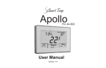
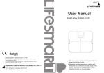
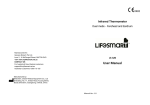
TM
Smart Temp
User Manual
Congratulations on the purchase of your new Electronic Thermostat!
Your new Smart Temp ISIS thermostat has been built using the best components and design
philosophy currently available. As a result, if properly installed your new electronic programmable
thermostat will provide you with many years of trouble free and reliable service.
Your Smart Temp ISIS Thermostat has been designed to be an attractive, highly reliable and easy
to use thermostat. By taking the time to read and understand these simple instructions you can
take advantage of many of the capabilities that are offered in the ISIS.
Overview
To assist in your understanding and use of the Isis, a brief description of the
functions and controls is given below. A more complete step-by-step
instruction on using the ISIS is given later in the manual.
ON / OFF Button
To turn the ISIS on, press the ON/OFF button. To turn the ISIS off press and hold the
ON/OFF button for 3 seconds. The Green ON/STBY LED will be illuminated when the
ISIS is on.
Set Buttons
The set (or desired) room temperature can be adjusted by pressing the plus or minus
SET buttons on the face of the ISIS. Each press will increase or decrease the set
temperature by 1 deg C. The ISIS is a single set point thermostat. For example, setting
the desired temperature at 21 deg C will bring on the AC heating if the room
temperature falls below 20 deg C and bring on the AC cooling if the room temperature
raises above 22 deg C. (Depending on the Deadband values set by the installer)
Prog Button
The ISIS is a 7 day programmable thermostat. This programmability permits you to set
the days and times that the ISIS automatically turns you AC System on and off. You
access these settings from the PROG button.
Alarm / Limits
This button has multiple functions. It is
used to enter the LOCK menu, the installer
menu and to cancel any equipment fault, over
or under temperature alarms that are present.
These functions are described later in the document.
ON/STBY LED
As the ISIS has two operational modes, two descriptions of this LED's
functions are given.
The ISIS in manual ON/OFF Mode.
This LED is illuminated when the ISIS is active and is not illuminated
when the ISIS is off.
This LED flashes when the 4-minute compressor short cycle protection
delay is active.
The ISIS in Programmable Mode.
This LED is always illuminated regardless of whether the ISIS is in Start
(System running) or Stop (System off) mode to indicate that the AC
system is under ISIS control.
This LED flashes when the 4-minute compressor short cycle protection
delay is active.
Clock Button.
The ISIS relies on an inbuilt real time clock to turn the system off and on at the times
required. The Clock button is used to set this real time clock.
OVERRIDE button
Pressing this button will turn the AC system on (in the last mode and at the last set
temperature) for an installer pre-set period of time. This override can be activated
regardless of whether the ISIS is in the manual OFF mode (Green ON/STBY LED off),
or the programmed STOP mode (Green ON/STBY LED on). When the override is
active a flashing clock symbol will be shown in the lower centre of the LCD.
To turn off the override simply press the OVERRIDE button once again.
ALARM LED
As well as being an AC controller, the ISIS is also capable of activating a remote
alarm should the room temperature fall out of a pre set temperature range. As well
as an alarm LED, the ISIS is also fitted with a normally open contact that closes
when an alarm condition exists.
If the AC equipment is fitted with a fault output, this can also activate the Alarm led
and fault relay if appropriately wired.
Important Considerations
Mode Button
The MODE button cycles the ISIS through Heat only, Cool Only, Auto-Change over or
Fan only operational modes. These modes are detailed below.
Remote Sensors
Smart Temp
Heat only mode The ISIS will turn on the AC Heating when the room
temperature falls below the set temperature. In Heat only mode the ISIS will
not bring on the AC Cooling regardless of the room and Set Temperature. In
Heat only mode the word “HEAT” will be displayed in the LCD.
Cool only mode - The ISIS will turn on the AC Cooling when the room
temperature raises above the set temperature. In Cool only mode the ISIS will
not bring on the AC Heating regardless of the room and Set Temperature. In
Cool only mode the word “COOL” will be displayed in the LCD.
Auto-change over mode - The ISIS will turn on the AC Heating if the room
temperature falls below the SET temperature and the AC Cooling if the room
temperature rises above the SET temperature. Auto changeover mode is
indicated by words, “HEAT” & “COOL” in the LCD.
Fan Only mode. In Fan only mode the ISIS will turn on the system fan for
continuous operation. The ISIS will not control the AC heating or cooling
system regardless of the room and set temperature. In Fan only mode a small
fan symbol will appear in the lower left of the LCD.
For security and convenience the ISIS may be
installed in a more remote or secure location. In
such applications the ISIS will measure the
temperature in the room to be controlled via a
remotely connected temperature sensor(s). Pict 1
shows the Smart Temp adjustable version of this
sensor.
It is important that consideration is given to this
sensor as placing hot items (such as kettles or
urns) or cold items (such as chest freezers) under
or in the vicinity of these sensors could result in
uncomfortable room temperatures.
Pict 1
Override
The ISIS has an after hour run on timer. This timer can be activated by pressing the
OVERRIDE button on the front of the thermostat, or alternatively via a remotely
wired switch. (Often, where there is a remote sensor installed and the override
option is used, the override switch will be mounted on the remote sensor).
To turn off the override simply press the override switch again.
Keyboard Lock
Auto Fan Button
The ISIS can control the system fan in two ways. Each press of the Auto Fan button
alternates the ISIS between Auto fan mode or continuous (Occupied) fan mode.
Auto Fan Mode - The fan will run only while the AC system is heating or
cooling. When the need for Heating or cooling stops, so does the fan.
Continuous Fan Mode (Occupied Fan). - In this mode, the fan will turn on
when the ISIS is on and remain on until the ISIS turns off. The fan will remain
on during this time regardless of whether there is a need to bring on the AC
system heating or cooling.
Please note - As the ISIS is a start / stop thermostat, when the system is OFF
(either in programmable or manual modes) the fan is also off.
For added security and to prevent un-authorised tampering with the ISIS program or
temperature settings the ISIS has a PIN protected key board lock. When this lock is
active, the only buttons that will respond are the OVERRIDE button and the Alarm
Reset button.
The procedure to lock and unlock the ISIS is provided in the Installation manual.
Only authorised persons will pe provided with this information in an effort to maintain
the security of the thermostat.
Temp
Making LifeSmart
Comfortable
Australia
Making Life Comfortable
Smart Temp
TM
The ISIS from Smart Temp Australia P/L is a multistage auto
change-over programmable thermostat. It offers industry
leading features, an impressive warranty and is extremely
simple to use and set up. By taking the time to follow these
instructions the ISIS will perform faultlessly and provide the
end user with many years of trouble free service.
Use this installer instruction sheet for mounting and setting up the
ISIS, and the User manual for information on programming and
setting the real time clock etc.
Mounting the ISIS or Optional Remote Sensor.
The ISIS can only be as accurate as the temperature sensor permits.
It is therefore essential that the ISIS (or remote sensor(s)) are
installed in a location that is typical of the ambient room temperature.
Do not install the ISIS in a draft, near a floor/wall/roof register.
Consideration also needs to be given to drafts that may be present
near external opening doors, chillers or windows. Where possible
mount the ISIS or temperature sensor out of direct sunlight and on
internal walls.
Further, when mounting the ISIS be aware of drafts that may travel
down the inside of walls, (especially if mounted on external walls). It
is important to fully block all cable entry holes to prevent any of these
drafts effecting the internally mounted ISIS temperature sensor.
It is recommended to mount the ISIS or remote sensors between
1.5 & 1.8 metres from the floor where possible.
Cabling
Normal “AC style” low voltage cabling can be used for the ISIS control
wiring. Where long cable runs are likely for the remote temperature
sensor and/or remote override switch it is recommended that
screened cable be used, especially where this cable is run close to
high voltage electrical wiring.
Do not used twisted DATA cable (CAT 5).
Wiring
Refer to the wiring diagrams on the reverse of this sheet to connect
the ISIS to the equipment. Please note, the ISIS is both a Heat Pump
& Heat Cool thermostat. The mode of operation is selected with
clearly marked jumpers. It is important that you have the jumpers in
the correct position for the type of AC equipment installed.
Programming & Set Up
DO NOT INSTALL THE LITHIUM BACK UP BATTERY UNTIL
AFTER THE REAL TIME CLOCK HAS BEEN SET.
After first connecting the AC power to the ISIS it is important to wait
15 ~ 20 seconds before attempting to press any buttons, this gives
the ISIS time to “BOOT UP” and run its internal diagnostics routine.
The ISIS will FAIL this initial BOOT sequence if the lithium battery is
installed at this point. If the battery has been mistakenly installed at
this point, remove the battery, power the ISIS down and wait 2~3
minutes before re applying power to the ISIS.
Use the programming instructions supplied in the user manual to set
the realtime clock and program the ISIS to the end user requirements.
After the ISIS has been set up and programmed insert the lithium
battery into the battery holder on the base of the main PCB.
Turn of the power to the ISIS wait 10 seconds and re connect the
power to confirm that the ISIS retains memory and the backup
battery and electronics functions correctly.
With the ISIS in Auto Change Over mode, test all thermostat modes
by both raising the set temperature above the ambient temperature
and verifying correct heater operation. Next lower the set
temperature to below the ambient temperature and verify the
correct operation of the cooling equipment.
Installation Instructions
Advanced Installer Functions
The ISIS has two concealed menus that are used to either fully lock
the thermostat (or restrict the temperature control range) or to adjust
the advanced installer functions. Each menu uses its own security
code. It is important that these security codes are only given to
authorised persons as these codes are fixed in ePROM and cannot
be changed. If these codes are compromised then unauthorised
persons will be able to make changes that will effect the
performance or efficiency of the AC system.
Locking & Unlocking the ISIS
Press the ALARM / RESET button. The ISIS will display “C50”.
Using the Set - button adjust this to read “C45”. Press the ALARM /
RESET to enter the Lock menu. Pressing the ALARM / RESET
button again will lock the ISIS.
Repeat this procedure to unlock the ISIS.
Setting Advanced Functions.
Press the ALARM / RESET button. The ISIS will display “C50”.
Using the Set + button adjust this to read “C55”. Press the ALARM /
RESET again to enter the Setup menu.
The ISIS will display “HL XX” This is the highest value you wish the
user to be able to adjust the set temperature to. This value can be
adjusted using the Set + or SET - buttons. Default value is 31
Press the ALARM / RESET button again to display “LL XX” This is
the lowest value you wish the user to be able to adjust the set
temperature to. This value can be adjusted using the Set + or
SET - buttons. Default value is 16
Press the ALARM / RESET button again to display “HA XX” This is
the value you wish the ISIS to activate the over temperature alarm.
This value can be adjusted using the Set + or SET - buttons.
Default value is 45
Press the ALARM / RESET button again to display “LA XX” This is
the value you wish the ISIS to activate the under temperature alarm.
This value can be adjusted using the Set + or SET - buttons.
Default value is 04
Press the ALARM / RESET button again to display “Db XX” This
permits adjustment of the dead band value, which is the value in
deg C between heat and cool modes that you wish the ISIS to
remain idle. This value can be adjusted using the Set + or SET buttons. Default value is 1 deg C.
Press the ALARM / RESET button again to display “Ot XX” This
activates the ISIS optimised start function “Ot 00” is optimised start
off. “Ot 01”is optimised start on. This value can be adjusted using
the Set + or SET - buttons. Default value is “OO” (off). Optimised
start will Start the ISIS before the programmed start time to ensure
the area is at the desired temperature by the programmed start time.
Press the ALARM / RESET button again to display “AH XX” This
sets the ISIS After Hours run on time period. This value can be
adjusted to values between “0” and “4” hours using the Set +
or SET - buttons.
Default value is “02” (Use “00” to set the after hours run on time period to Off)
Press the ALARM / RESET button again to display “ t 00”
This permits you to adjust the temperature calibration of the
thermostats temperature sensor. This value can be adjusted to
o
o
values between “-6 c” and “+6 c” using the Set + or SET - buttons.
Default value is “00” (Calibration Offset is nil)
Press the ALARM / RESET button again to return the ISIS to normal
mode.
Electrical Diagram
Flat cable connector
ISIS Heat Cool Configuration
ISIS
24 Volt Control
Jumper
Position
Heat / Cool Connections
Link must be installed
between RH &RC
Y1 Y2 W1 W2 W3 G1 N/A AL AL Rc
Fault Input
Remote
Sensor
Remote
Override
Rh
C
Aux
T1
T1
T0
T0
24V Active
24V Common
JP3 Jp4 Jp5 JP6 JP7
Off
4 min
Time
Delay
Clock
24 Hour
N/A
On
Time
Delay
Off
Clock
AM/PM
N/A
Must be
in this
position
Fan ON
immediate
with Heat call
(Elec. Heat)
Fan controlled
by plenum switch
(Gas. Heat)
Position A = Internal Sensor
JP-1 Position
B = Remote Sensor
Alarm Output
Dry Contact (Max 24V)
Cool 1
Cool 2
Heat 1
Heat 2
Heat 3
Fan
ISIS Heat Pump Configuration
Flat cable connector
ISIS
24 Volt Control
Jumper
Position
JP3 Jp4 Jp5 JP6 JP7
Off
4 min
Time
Delay
Clock
24 Hour
N/A
Rev Valve
Energize “O”
(cooling)
On
Time
Delay
Off
Clock
AM/PM
N/A
Must be Rev Valve
in this Energize “B”
position (heating)
Position A = Internal Sensor
JP-1 Position
B = Remote Sensor
Heat Pump Connections
Link must be installed
between RH &RC
Y1 Y2 O/B W2 W3 G1 N/A AL AL Rc
Fault Input
Aux
Remote
Sensor
T1
T1
T0
T0
Remote
Override
Rh
C
24V Active
24V Common
JP7 Fan / RV Select
Jp6 Heat Pump / Heat Cool select
JP 5 Factory USE ONLY - N/A
Jp4 12/24 hour clock
Jp3 Compressor Protection
Alarm Output
Dry Contact (Max 24V)
Compressor 1
Compressor 2
Rerversing Valve
Auxilary Heat
Fan
Jp1
Internal or
Remote Sensor
Optional 240V Interface available
Specifications
Range:
Deadband:
Alarms:
After Hours:
Cal Offset:
Resolution:
Accuracy:
Load rating:
Lithium Bat:
5° to 35° c.
1~5 deg C (Adjustable)
2~45 deg C (Adjustable)
0~4 Hours (Adjustable)
+/- 6 C (Adjustable)
1°c
+/- 0.3°c
2 Amps @ 24 VAC max.
10 Years
Voltage:
Connectors:
Material:
Weight:
Size:
Warranty:
24VAC.
Screw type.
PC/ABS
210g
82 x 140 x 27
1 year R.T.B
Smart Pak
B
A
Battery
Holder
Optional Adjustable Remote Sensor
(Non Adjustable and Duct Mount Sensors available)
Smart Temp
(Or 8 weeks accumulated power outage)
Rev G June 2007
Smart Temp Australia Pty Ltd
Optional Smart Pak Cover Shown
Unit 20, 1488 Ferntree Gully Road
Knoxfield 3180 Victoria Australia
Phone:(03) 9763 0094 Fax (03) 9763 0098
www.thermostat.com.au
SmartAustralia
Temp
Making Life Comfortable
Programming your ISIS
7
Setting the Desired Temperature
Use the SET + button to increase the desired room temperature. Use the
SET - button to decrease the desired room temperature. While pressing
these buttons the ISIS will display both the SET temperature and the
current room temperature on the LCD. Normally the ISIS display will
alternate between Temperature Display & Time display.
Setting the Clock
Please note. During programming and set up, the ISIS will resume normal
mode if no buttons are pressed for 15 seconds. This is an important
consideration during set up of the ISIS as if there is to long a period
between pressing buttons the thermostat will return to normal mode forcing
you to commence the programming procedure from the start.
As the ISIS can operate as a programmable thermostat it is essential that
the clock is set correctly otherwise the ISIS will not operate the AC system
at the desired times.
07 00
CLOCK
1
2
3
4
Press the CLOCK button once. The
Hours will flash in the LCD. Using the Set
+ or SET - button adjust the hours to the
correct time making sure that the AM or
PM (if in 12 hour mode) indicator is
correct. (Pict 2)
Press the CLOCK button again. Now the
minutes flash in the LCD. Using the Set +
or SET - button adjust the minutes to the
correct time. (Pict 3)
Press the CLOCK button again. Now the
day of the week flash in the LCD. Using
the Set + or SET- button adjust the day
indication to the correct day. (Pict 4)
Press the Clock button once again. The
ISIS clock is now set.
AM
Pict 2
07 26
CLOCK
AM
LCD but this time we are adjusting the
Start time for the Tuesday program.
Repeat steps 2 through 6 to adjust the
hours and minutes of the remaining
Monday to Sunday start and stop
times. (Pict 10)
08 32
SET
MON
AM
PROGRAM
STOP
1
Pict 9
12 03
SET
Should you wish the ISIS to remain in the
OFF mode completely for one day
(I.E. Sunday) set the Start & Stop times to
the same value.
TUE
PM
PROGRAM
1
START
Pict 10
TIP: Press the clock button to advance rapidly through the days while in
program mode.
Please note. The ISIS is able to operate as a manual (non
programmable thermostat) or as a 7 day programmable thermostat as
previously described.
To operate the ISIS in Non Program or manual mode (Not under any
automatic time clock control) press and hold the PROG button for 5
seconds. When the ISIS is running in non program mode the program
indicator in the lower right of the ISIS LCD will be missing. This ISIS can
then be manually turned off and on when required with the ON/Off button.
To reactivate program mode simply press and hold the “prog” button for 5
seconds until the Program indicator is active.
Pict 3
07 26
CLOCK
AM
SET
Used to adjust the desired or “set” temperature.
TUE
ON/STB
Indicates System Status
Indicates Comp Protection delay active.
Pict 4
ALARM
Indicates Over / Under Temperature alarm active.
Indicates Equipment Fault.
Programming the ISIS to turn on and off at your required times.
Please note. During programming and set up, the ISIS will resume normal
mode if no buttons are pressed for 15 seconds. This is an important
consideration during set up of the ISIS as if there is to long a period
between pressing buttons the thermostat will return to normal mode forcing
you to commence the programming procedure from the start.
ON / OFF
Toggles the ISIS between on and off modes.
MODE
Used to select Heat, Cool, Auto or Fan Only Mode.
AUTO FAN
Used to Select Auto or Manual Fan mode.
The ISIS is a 7 day programmable thermostat. Each day of the week can
have a different start and stop time for each of the program “starts” and
program “stops”. For example, the ISIS can turn the AC system on at 9:30
am Sunday and off again at noon Sunday.
ALARM LIMITS / RESET
Used to Reset Over/Under Temp alarms.
Used to enter Lock / Unlock mode.
Used to acknowledge equipment fault
For simplicity, your ISIS has a default factory installed program of 7:30 AM
Start ~ 5:00 PM Stop Monday to Friday. This default program may be
modified if required
OVERRIDE
Used to toggle the Two Hour System Run Override
To program the ISIS
CLOCK
Used to set the ISIS Real Time clock.
1
2
Press the PROG button and the time will flash in the LCD. Monday
is displayed and the program indicator on the lower right of the LCD
is on. (Pict 5)
Press the PROG button again, The Hour flashes, START and
Program 1 is displayed. Note that
Monday is displayed indicating that this
SET
days program is being set. Press the
Set + or SET - button to adjust the hours
PM
to the time you want the ISIS to turn the
PROGRAM
AC system on during Monday. (Pict 6)
1234
Press the PROG button again, Now the
Pict 5
Minutes flash, Press the Set + or SET SET
button to adjust the minutes to the time
AM
you want the ISIS to turn the AC system
on. (Pict 7)
PROGRAM
START
1
Press the PROG button; the Hour
Pict 6
flashes again but this time the word
STOP is displayed in the LCD. Using the
SET
Set + or SET - button adjust the hours to
AM
the time you wish the ISIS to turn the AC
system OFF. (Pict 8)
PROGRAM
START
1
Press the PROG button again and the
Pict 7
minutes flash. Using the Set + or SET button adjust the minutes to the time you
SET
wish the ISIS to turn the AC system OFF.
AM
(Pict 9)
6 Press the PROG button again; the
PROGRAM
Hour flashes again with the
STOP
1
word START shown in the
Pict 8
09 26
MON TUE WED THU FRI SAT SUN
3
06 00
MON
4
PROG
Used to program the ISIS start and Stop times.
Used to Toggle between Program & Manual Modes.
Time & Temperature Display
AM/PM Indicator
Auto Fan on indicator
(Not used in 24 Hour clock mode)
Note: Both HEAT and
COOL on together
indicates Auto Changeover mode on.
88 88
SET CLOCK
Heat mode indicator
Cool mode indicator
AUTO FAN
HEAT
COOL
Stage indicators
TEMP
MON TUE WED THU FRI SAT SUN
Day indicator
Fan only mode indicator
START
Program Start Indicator
Program Indicator
06 42
(Flashes when in override mode)
STOP
AM
PM
PROGRAM
1234
Current Program running
Program Stop Indicator
MON
5
SmartAustralia
Temp
08 00
MON
Ver 06-07
Making Life Comfortable
Unit 20, 1488 Ferntree Gully Road
Knoxfield 3180 Victoria Australia
Phone:(03) 9763 0094 Fax (03) 9763 0098
www.thermostat.com.au