1
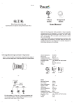
Inground 200
™
User Manual
Single Color
Dimensions
Measurements are in millimeters
340
7
310
496
© 2004-2009 Martin Professional A/S. Information subject to change without notice. Martin
Professional A/S and all affiliated companies disclaim liability for any injury, damage, direct or
indirect loss, consequential or economic loss or any other loss occasioned by the use of, inability to use or reliance on the information contained in this manual. The Martin logo, the Martin
name and all other trademarks in this document pertaining to services or products by Martin
Professional A/S or its affiliates and subsidiaries are trademarks owned or licensed by Martin
Professional A/S or its affiliates or subsidiaries.
P/N 35000152, Rev C
Contents
Introduction . . . . . . . . . . . . . . . . . . . . . . . . . . . . . . . . . . . . . . . . . . . . . . . 5
Inground 200 model range. . . . . . . . . . . . . . . . . . . . . . . . . . . . . . . . . .
Optics and accessories . . . . . . . . . . . . . . . . . . . . . . . . . . . . . . . . . . . .
Mains power options . . . . . . . . . . . . . . . . . . . . . . . . . . . . . . . . . . . . . .
Included items . . . . . . . . . . . . . . . . . . . . . . . . . . . . . . . . . . . . . . . . . . .
5
5
6
6
Safety information . . . . . . . . . . . . . . . . . . . . . . . . . . . . . . . . . . . . . . . . . 6
Operation . . . . . . . . . . . . . . . . . . . . . . . . . . . . . . . . . . . . . . . . . . . . . . . . . 8
General guidelines . . . . . . . . . . . . . . . . . . . . . . . . . . . . . . . . . . . . . . . . 8
Service and troubleshooting . . . . . . . . . . . . . . . . . . . . . . . . . . . . . . . . 9
Clearing excess humidity . . . . . . . . . . . . . . . . . . . . . . . . . . . . . . . . . .
Cleaning. . . . . . . . . . . . . . . . . . . . . . . . . . . . . . . . . . . . . . . . . . . . . . .
Seals . . . . . . . . . . . . . . . . . . . . . . . . . . . . . . . . . . . . . . . . . . . . . . . . .
Component removal and reinstallation . . . . . . . . . . . . . . . . . . . . . . .
10
10
11
11
Set-up and adjustment . . . . . . . . . . . . . . . . . . . . . . . . . . . . . . . . . . . . 20
Beam adjustment . . . . . . . . . . . . . . . . . . . . . . . . . . . . . . . . . . . . . . . . 20
Troubleshooting . . . . . . . . . . . . . . . . . . . . . . . . . . . . . . . . . . . . . . . . . . 22
Specifications: Inground 200 Single Color . . . . . . . . . . . . . . . . . . 23
Ordering information. . . . . . . . . . . . . . . . . . . . . . . . . . . . . . . . . . . . . . 26
1. Introduction
Thank you for selecting the Martin™ Inground 200™ Single Color, a 150
watt uplight designed for permanent burial installation.
This User Manual contains details of how to operate and service this fixture.
For details of installing the Inground 200 Single Color, please refer to the
Installation Guide shipped with the product. The most recent versions of the
Installation Guide and this User Manual are also available in the Product
Support area of the Martin website at http://www.martin.com
Inground 200 model range
The Inground 200 is available in two models:
Inground 200 Single Color
The Inground 200 Single Color can be operated with or without a color filter
and can be manually dimmed, but it is not programmable and cannot be
controlled by DMX.
Inground 200 CMY
The Inground 200 Full Spectrum CMY offers seamless full spectrum colormixing, giving a virtually limitless color palette, and 0-100% intensity
control. It can be programmed to run synchronized stand-alone light shows
with pre-defined start/stop times using a Windows PC with Martin MUM™
software, or it can be operated using a DMX controller. A separate user
manual, P/N 35000153, exists for this product.
Optics and accessories
The following optional lenses are available for the Inground 200:
•
•
•
•
Medium – 32° one-tenth peak angle
Wide – 56° one-tenth peak angle
Very wide – 98° one-tenth peak angle
Wallwash
A range of accessories is available for the Inground 200. See “Ordering
information” on page 26. See also www.martin.com for the most recent
information.
Introduction
5
Mains power options
Inground 200 Single Color and CMY models are both available in three
configurations to match local AC mains power:
• 210 V, 60 Hz (US model)
• 277 V, 60 Hz (US model)
• 230 V, 50 Hz (EU model)
Included items
The Inground 200 Single Color is supplied with the following items:
• Philips CDM-SA/T 150W/942 lamp
• Silica gel sachet inside fixture for shipping (must be removed and
disposed of)
• Silica gel sachet packed separately in sealed aluminum bag (must be
fastened inside fixture and fixture closed within 20 minutes of opening
aluminum bag)
• 3 m (9.8 ft.) hard-wired power cable tail
• Installation guide
• User manual
2. Safety information
Warning!
This product is not for household use.
This product presents risks of lethal or severe injury due to fire, heat,
electric shock and lamp explosion.
Read this guide before operating the fixture, follow the safety precautions
listed below and observe all warnings in this guide and on the fixture.
If you have questions about how to operate or service the fixture safely,
please contact your Martin supplier or call the Martin 24-hour service
hotline on +45 8740 0000, or in the USA on 1-888-tech-180.
Guarding against electric shock
• Isolate the fixture from AC power before removing or installing the lamp,
fuses, or any part.
• Always ground (earth) the fixture electrically.
6
Safety information
• Use only a source of AC power that complies with local building and
electrical codes and has both overload and ground-fault protection.
• Refer any service not described in this user manual to a Martin service
technician.
Lamp safety and eye protection
• Never operate the fixture with missing or damaged lenses and/or covers.
• Do not stare directly into the light. Never look at an exposed lamp while it
is lit.
• Wear safety glasses during beam adjustment.
• Use only approved lamp types (see “Source” on page 23).
• Replace the lamp if it becomes defective or worn out. The average life of
the Philips CDM-SA/T 150W/942 lamp supplied with the Inground 200 is
9000 hours. If one of the approved alternative lamp types listed under
“Source” on page 23 is fitted, see the lamp supplier’s documentation.
Guarding against burns and fire
• Allow the fixture to cool for at least 15 minutes after use before opening it
for service or adjustment.
• Wear heat-resistant safety gloves during beam adjustment.
• Never attempt to bypass the thermostatic switch or fuses. Always replace
defective fuses with ones of the specified type and rating.
• Keep all combustible materials (for example fabric, wood, paper) at least 1
meter (39 inches) away from the fixture. Keep flammable materials well
away from the fixture.
• Ensure that litter, dry leaves or other combustible materials cannot
accumulate on or near the fixture.
• Prevent vehicles from being parked over or near fixtures – including unlit
fixtures that may later be switched on.
• Do not illuminate surfaces within 0.5 meters (20 inches) of the fixture.
• Install the fixture outdoors or in a well ventilated area.
• The exterior of the fixture can become very hot, up to 80° C (176° F)
during normal operation. Ensure all local safety regulations and legal
requirements are observed, and take appropriate measures to warn or
restrict access.
• Do not modify the fixture or install other than genuine Martin parts.
• Never place filters or other materials over the front glass.
Guarding against injury
• The front glass can be slippery, especially when wet. Ensure that
pedestrians are warned and/or kept away from the fixture.
• Block public access during service.
Safety information
7
3. Operation
General guidelines
The Inground 200 Single Color does not have a power on/off switch. The
lamp strikes as soon as power is applied to the fixture via the power input
cable.
To avoid voltage drops which may result if many lamps strike at the same
time, apply power to circuits one after the other at intervals of a second or
two if you have groups of fixtures on separate circuits in the installation.
For optimum lamp life and performance, allow the lamp to warm up fully for
five minutes before cutting power to the fixture.
8
Operation
4. Service and
troubleshooting
This section describes service procedures that can be performed by the
user. Refer all service not described here to a qualified Martin Architectural
technician.
Warning!
Isolate the fixture from power and allow to cool for at least 15
minutes before removing any cover.
Trim ring
Front glass with seal
Lens
Beam adjustment ring
Lamp module
Housing
Power compartment
Service and troubleshooting
9
Clearing excess humidity
Each time the Inground 200 is opened, the silica gel anti-humidity sachet
fastened to the lamp module must be removed and a new item fastened in
its place (see “Anti-humidity sachet replacement” on page 13).
Excess humidity inside the fixture can be experienced in the following
situations:
• The installation well is waterlogged
• The trim ring and front glass are not sealed correctly on the top of the
housing.
• The anti-humidity sachet fastened to the lamp module is saturated or
missing.
Warning!
If you clear excess humidity as described below:
• The exposed lamp and internals present a risk of electric shock,
burns and ultra-violet radiation. A hot discharge lamp is under
pressure and there is a risk of lamp explosion. Block public access,
wear safety glasses and heat-resistant gloves, handle the lamp
module with care, and do not look into the light beam.
• Choose dry weather.
• Ensure that no dust or objects enter the fixture while it is open.
If there is excess humidity in the Inground 200, condensation will appear
under the front glass. To eliminate excess humidity:
1. Check that the installation has adequate drainage and that the top glass
and trim ring are sealed correctly. Rectify any problems.
2. Install a new anti-humidity sachet and reinstall the front glass
immediately (new anti-humidity sachets are available from Martin
suppliers – see “Spare parts” on page 26).
Cleaning
Wash the front glass with a soft brush or sponge and a mild, non-abrasive
car washing detergent. Wipe off traces of detergent with a sponge or brush
soaked in clean water.
Do not use a hose or high-pressure spray equipment on the fixture. The
Inground 200 is water-resistant, but is not designed for submerged
operation. Excessive use of water may flood the installation sleeve.
10
Service and troubleshooting
Seals
To maintain the fixture’s resistance to dust and moisture, it is important that
you replace seals and covers carefully after removal.
The power compartment cover Allen screws must first be screwed in until
they are finger-tight, and then given an extra 3/4 to one full turn. This will
ensure that seals are compressed by about one-third. When fitting the front
glass trim ring, use a torque driver and cross-tighten the screws gradually to
a torque of 6 Nm (4.4 ft.-lbs.).
Warning!
Do not use silicone or any other kind of sealant on the front glass seal,
front glass, housing or trim ring. Doing so will invalidate the product
warranty.
The silicone seals should maintain their sealing ability for the life of the
fixture. However, when servicing the fixture, note the condition of the seals
and replace any seal that is cracked, torn, brittle, or inflexible. Replacement
seals may be ordered as follows:
Front glass seal ....................................................P/N 20600441
Power compartment seal ......................................P/N 20600450
Component removal and
reinstallation
Tasks such as beam adjustment and lamp replacement require the removal
and refitting of certain components. This section contains instructions for
these procedures.
Besides safety gloves and safety glasses, you will need a torque driver with
a range that includes 6 Nm (4.4 ft.-lbs.) as well as 4mm and 2.5mm Allen
bits for these procedures.
Warning!
Danger of burns, electric shock and lamp explosion!
• These procedures must be carried out by authorized electrical
personnel and in clean, dry conditions only.
• Wear heat-resistant safety gloves and safety glasses throughout
these procedures.
• Do not look directly into the lamp.
• Make sure that nothing falls into the fixture while the front glass and
lens are removed.
Service and troubleshooting
11
Important!
Any damaged seals or screws must be replaced with new items. Two
spare 4mm countersunk Allen screws for the trim ring are supplied
with the fixture.
The front glass seal, its seating surface in the housing, the front glass
and the trim ring must all be perfectly clean and dry during reinstallation to maintain a waterproof seal.
Do not use silicone or any other kind of sealant on the front glass seal,
front glass, housing or trim ring. Doing so will invalidate the product
warranty.
The anti-humidity sachet inside the fixture must be renewed each time
the fixture is opened for service.
Removing the front glass and lens
The front glass and lens must be removed for beam adjustment and all
other service interventions.
To remove the front glass and lens:
1. Isolate the fixture from AC power and ensure that power cannot be
reapplied, even accidentally. Allow the fixture to cool for at least 15
minutes.
2. Brush or if possible vacuum sand, dirt, etc. away and clean the top of the
fixture and the surrounding area to ensure that dirt does not fall into the
fixture.
3. Remove the six countersunk 4mm Allen screws and lift the trim ring off
the fixture
4mm
4. Taking care to avoid damaging the seal, lift off the front glass and its seal.
5. The lens is under the front glass, resting on the beam adjustment ring on
top of the lamp module. Lift the lens out of the fixture.
6. If a light spill limiter ring (shading plate) and/or a louvered anti-glare plate
are installed under the lens, lift them out of the fixture.
12
Service and troubleshooting
Removing the lamp module
The lamp module must be removed for replacement of the anti-humidity
sachet, lamp replacement, and all other service interventions apart from
beam adjustment.
To remove the lamp module:
1. Remove the front glass and lens, then any shading pate and/or louvered
anti-glare plate fitted, noting the orientation of the louvered anti-glare
plate (see “Removing the front glass and lens” on page 12).
2. Do not loosen the beam adjustment screws and do not disturb the beam
adjustment settings, or the beam will have to be readjusted. Holding the
lamp module by the beam adjustment ring, gently lift the whole module
upwards until it is clear of the housing.
3. Note the positions of the lamp module wiring connectors, then disconnect
them and lift the lamp module away from the fixture.
Anti-humidity sachet replacement
Each time the Inground 200 is opened for service, or to clear excess
humidity at any time, the silica gel anti-humidity sachet fastened to the lamp
module inside the fixture must be removed and a new item fastened in its
place. The fixture must be closed within 20 minutes of opening the
aluminum bag holding the new anti-humidity sachet.
New anti-humidity sachets are available from Martin suppliers (see “Spare
parts” on page 26 for details).
To renew the anti-humidity sachet:
1. Remove the front glass, lens and lamp module (see “Removing the front
glass and lens” on page 12 and “Removing the lamp module” on page
13).
Service and troubleshooting
13
2. See illustration below. Cut the cable tie holding the silica gel antihumidity sachet to the side of the lamp module above the cooling fan
and remove the sachet.
Cooling fan
3. Remove a new anti-humidity sachet from its sealed aluminum packet
and fasten it with a cable tie in the place of the sachet you have
removed. You must now reinstall components and close the fixture within
20 minutes.
Lamp replacement
The Inground 200 is supplied with a Philips CDM-SA/T 150W/942 discharge
lamp. The Inground 200 may be used with the following lamp types:
Lamp
Efficiency
Color Temp.
Average Life
Philips CDM-SA/T 150W/942
88 Lm/W
4200 K
9 000 hours
Philips CDM-T 150W/830
93 Lm/W
3000 K
12 000 hours
Osram HCI-T 150W/WDL*
97 Lm/W
3000 K
12 000 hours
Osram HCI-T 150W/NDL*
91 Lm/W
4200 K
12 000 hours
Table 1: Lamp specifications
*WDL = warm daylight, NDL = neutral daylight
If in any doubt about suitable lamp types, consult your Martin Architectural
dealer.
14
Service and troubleshooting
Important!
Installing any other lamp type may damage the fixture.
Warning!
Allow the fixture to cool for at least 15 minutes before removing the
front glass.
To replace the lamp:
1. Remove the front glass, lens and lamp module (see “Removing the front
glass and lens” on page 12 and “Removing the lamp module” on page
13).
2. Turn the lamp module upside down and loosen – but do not remove – the
three 2.5mm Allen screws on the lamp baseplate pillar bolts.
2.5mm
Service and troubleshooting
15
3. Turn the lamp baseplate anti-clockwise a few degrees to release it from
the three Allen screws, then gently lift the baseplate assembly off the
lamp module.
4. Remove the old lamp from the socket. Holding the new lamp by its
ceramic base - do not touch the glass bulb - insert it firmly and squarely
into the lamp socket. Clean the glass bulb with an alcohol wipe or a
clean, lint-free cloth wetted with 99.9% isopropyl alcohol.
5. Refit the lamp baseplate on the three pillar bolts, twisting clockwise to
locate it, and retighten the three Allen screws to secure it.
6. If no further service is required, fasten a new anti-humidity sachet to the
lamp module, then reinstall the lamp module, any shading or anti-glare
plates originally fitted, the lens and the front glass (see “Anti-humidity
sachet replacement” on page 13, “Reinstalling the lamp module” on page
18 and “Reinstalling the lens and front glass” on page 19).
16
Service and troubleshooting
Accessing the power module
The PSU (power supply unit) and ballast are located in the power
compartment in the base of the housing.
Removing the power module
1. Remove the front glass, lens and lamp module (see “Removing the front
glass and lens” on page 12 and “Removing the lamp module” on page
13).
2. The power compartment is the larger of the two compartments in the
bottom of the fixture. Note the positions of the connectors and disconnect
the connections to this compartment.
3. See illustration below. Remove the five 5mm Allen screws from the power
compartment cover plate.
4. Holding the cover plate by its wire service handle, lift it carefully upwards,
avoiding damage to the seal. The power components are mounted on the
cover plate itself, forming the power module. Lift this entire module
carefully out of the fixture.
5. The power compartment and cable inlet compartment share one seal.
Check this seal for damage. If it is damaged or brittle, it must be replaced
with a new seal (available from your Martin Architectural dealer: P/N:
20600450). Cable entry is sealed for life, so replacement of this seal is
the only reason ever to open the cable inlet compartment.
Service and troubleshooting
17
6. After service in the power compartment is completed, ensure that the
seal and mating surfaces in the power compartment cover plate and
housing are perfectly clean and dry.
Note: Do not apply silicone or any other type of sealant to the seal or
mating surfaces. Doing so will invalidate the product warranty.
7. Lower the power module carefully into place, being careful not to damage
the seal or trap wires.
8. Tighten the five power compartment cover plate Allen screws by hand
until they are finger tight. Then use an Allen key to further tighten each
screw by between three quarters of a turn and one full turn. Screws will
now be tight enough to achieve a waterproof seal.
Note: Do not overtighten, or you may damage the seal and invalidate the
product warranty.
9. If no further service is required, fasten a new anti-humidity sachet to the
lamp module, then reinstall all components as described in this chapter
before reapplying power.
Connecting lamp leads to the starter
If it ever becomes necessary to disconnect the lamp wiring harness from
the starter, make sure that the wires in the harness are reconnected to the
starter as follows:
• White wire with blue sleeve to screw terminal marked N
• White wire without sleeve to screw terminal marked LP
• Wire without insulation (bare copper) and ring terminal to chassis where
the ground (earth) wire was originally fastened.
Reinstalling the lamp module
1. Remove a new anti-humidity sachet from its sealed aluminum packet and
fasten it with a cable tie in the place of the existing sachet (see “Antihumidity sachet replacement” on page 13). You must now close the
fixture within 20 minutes.
2. Reconnect the lamp module wiring connectors.
3. Note the position of the screw in the lamp module seating in the housing.
Lower the lamp module into the housing, rotating it if necessary so that
the notch in the top of the lamp module engages with the screw. The
lamp module is now correctly oriented.
4. If beam settings have been disturbed, readjust the beam (see “Beam
adjustment” on page 20).
18
Service and troubleshooting
Reinstalling the lens and front glass
Important!
Before reinstalling the lens and front glass, ensure that the antihumidity sachet fastened to the lamp module has been replaced with a
new item.
Replace any damaged seals or screws with new items.
The front glass seal, its seating surface in the housing, the front glass
and the trim ring must all be perfectly clean and dry to maintain a
waterproof seal.
Inspect the front glass seal for signs of damage or deterioration before
refitting. Replacement front glasses and seals are available from
Martin Architectural dealers (standard front glass: P/N 41700007, front
glass seal: P/N 20600441).
Inspect the six countersunk Allen screws from the trim ring before
reuse. Threads must be clean and undamaged. Two spare screws are
supplied with the fixture. Replacement screws are available from
Martin Architectural dealers (P/N: 08111314)
Do not use silicone or any other kind of sealant on the front glass seal,
front glass, housing or trim ring. Doing so will invalidate the product
warranty.
1. Inspect the front glass seal for damage before refitting. Replacement
front glasses and seals are available from Martin dealers (standard front
glass: p/n 41700007, front glass seal: p/n 20600441).
2. Reinstall any shading plates and louvered anti-glare plates that were
originally installed.
3. Refit the lens by lowering it into the housing, rotating the lens if
necessary so that the screw in the seating engages in the notch in the
lens flange.
4. Any dirt between the front glass seal and housing or front glass seal and
trim ring will prevent a proper seal and encourage moisture build-up
inside the fixture, so clean the mating surfaces carefully. The trim ring
overlaps the top of the fixture and any hard obstruction immediately
beside the fixture will prevent the trim ring from sealing properly, so
ensure that a space the diameter of the trim ring around the top of the
fixture is clear at the level of the top of the housing.
5. Place the front glass complete with its seal in the top of the housing and
place the trim ring over the front glass.
6. Inspect the six countersunk Allen screws from the trim ring. Threads
must be clean and undamaged. Replace any damaged screws. Two
spare screws are supplied with the fixture. Replacement screws are
available from Martin dealers (p/n: 08111314). To make future service
easier, apply a small amount of copper-based or silicone grease to the
threads of the trim ring screws.
Service and troubleshooting
19
7. See illustration on right. Gradually
cross-tighten the trim ring screws in the
sequence illustrated to 6 Nm
(4.4 ft.-lbs.).
Important!
Cross-tighten gradually. Do not exceed
the maximum torque of 6 Nm
(4.4 ft.-lbs.), or you may distort the trim
ring and damage the seal. This will
impair the Inground 200’s waterproof
properties and invalidate the product
warranty.
A
F
C
D
E
B
5. Set-up and adjustment
This section assumes that the Inground 200 has already been
commissioned. For installation details, see the Inground Installation Guide
supplied with the product and available for download under Product Support
on the Martin website at www.martin.com.
B e a m a d j u s tm e n t
Correct adjustment of the beam of the Inground 200 is critical for correct
illumination of the target. Adjustment must be carried out with the lamp
powered on and is best carried out after dark.
Warning!
Danger of burns, electric shock and lamp explosion!
• Beam adjustment must be carried out by authorized electrical
personnel and in clean, dry conditions only.
• Wear heat-resistant safety gloves and safety glasses throughout this
procedure.
• Do not look directly into the lamp.
• Make sure that nothing falls into the fixture while the front glass and
lens are removed.
To adjust the beam:
1. Depending on whether the Inground 200 has been in operation or not,
ensure that the fixture is at optimum temperature for adjustment by
following one of these two alternatives:
a) If the fixture has been in operation before you want to adjust the beam,
do not switch it off. Instead, remove the front glass and lens (see
20
Set-up and adjustment
“Removing the front glass and lens” on page 12) and wait 15 minutes
for the lamp module to cool slightly.
b) If the fixture has not been in operation before you want to adjust the
beam, remove the front glass and lens (see “Removing the front glass
and lens” on page 12), apply power and wait 15 minutes for the lamp
to warm up to operating temperature.
2. Loosen the two 2.5mm beam adjustment ring Allen screws (A) and rotate
the lamp module until it can be tilted towards the target.
A
2.5mm
A
A
B
3. Make sure the beam adjustment ring screws (A) are pushed out towards
the edges of the lamp module to engage the retaining clips, and retighten
the screws to clamp the beam adjustment ring in place.
4. Loosen the tilt adjustment Allen screw (B) on the side of the beam
adjustment ring. Adjust the tilt angle from 0 - 15° by pushing down gently
on the side of the lamp module top plate closest to the target. Retighten
the tilt adjustment screw (B) to lock tilt adjustment. Replace the lens.
5. Check that the target is illuminated as intended. If not, repeat step 4.
When the desired illumination is obtained, the tilt angle can be read from
the guide next to the tilt adjustment screw and noted for future reference.
6. Disconnect the fixture from power, lift the lens and lamp module out of
the fixture temporarily to renew the anti-humidity sachet, then reinstall all
components (see “Anti-humidity sachet replacement” on page 13,
“Reinstalling the lamp module” on page 18 and “Reinstalling the lens and
front glass” on page 19) before reapplying power.
Set-up and adjustment
21
6. Troubleshooting
Problem
Probable cause(s)
Remedy
Inadequate front glass
sealing.
Ensure that front glass and
trim ring make a correct seal
in top of fixture housing.
Check that there are no
obstructions under the trim
ring that may have prevented it
from fastening down correctly
onto the top of the housing.
Ensure that trim ring screw
torque is 6 Nm (4.4 ft.-lbs.).
Replace front glass seal if
damaged.
Excess moisture build-up in
fixture (condensation under
front glass).
Install a new sachet and close
Silica gel anti-humidity sachet fixture within 20 minutes of
fastened to lamp module is
opening new sachet’s
saturated or missing.
aluminum bag
Flooded installation well.
Fixtures cut out after 1 - 3
hours. Problem is relieved if
water is poured into fill
material around fixture.
22
Improve drainage.
Temperature too high: thermal Modify fill material in sleeve to
cutout shutting down power to improve heat conduction away
avoid overheating.
from fixture.
No response from fixture when No power to fixture.
power is applied.
Mains fuse blown.
Check power cables.
Lamp blown.
No light, lamp cuts out
intermittently, or burns out too
quickly.
Fixture or lamp is too hot.
Disconnect fixture and replace
lamp.
Troubleshooting
Replace fuse.
Allow fixture to cool. If problem
persists, contact service
technician.
7. Specifications: Inground
200 Single Color
Specifications subject to change without notice
Physical
Height ................................................................................................. 496 mm (19.53 in.)
Trim ring outer Ø ................................................................................. 340 mm (13.39 in.)
Trim ring thickness .................................................................................... 7 mm (0.28 in.)
Housing top flange outer Ø .................................................................. 310 mm (12.2 in.)
Weight ............................................................................................. approx. 20 kg (44 lb.)
Included items
User manual, Inground 200 Single Color ................................................... P/N 35000152
Installation guide ........................................................................................ P/N 35000151
Philips CDM-SA/T 150W 942 lamp ............................................................ P/N 97010111
Silica gel anti-humidity sachet (inside product, must be removed during installation)
Silica gel anti-humidity sachet (separate, must be fastened in fixture during installation)
Two spare trim ring screws (4mm Allen cap, countersunk)
Construction
Housing ......................... Combination of extruded and high pressure die-cast aluminium
Finish .........................................................................................................Black anodized
Trim ring......................................................................................Various options available
Fasteners....................................................... M6 stainless steel Allen cap screws (6 off)
Front glass...................................Ø 254 mm (10 in.), 19 mm (3/4 in.) tempered optiwhite
Ingress protection factor .......................................................................................IP 65/67
AC power input .............................................................3 m (9.8 ft.) cable tail, hard-wired
Front glass weight resistance (load from pneumatic tire) ................ 5 000 kg (11 000 lb.)
Fixture overall weight resistance
(in installation sleeve with suitable groundwork) ......................... 5 000 kg (11 000 lb.)
Source
Lamp ...................................................................................................... 150 W discharge
Base ........................................................................................................................... G12
Approved models................................ Philips CDM SA/T 150W/942 (lifetime: 9 000 hrs.)
Philips CDM-T 150W/830 (lifetime: 12 000 hrs.)
Osram HCI-T 150W/WDL (lifetime: 12 000 hrs.)
Osram HCI-T 150W/NDL (lifetime: 12 000 hrs.)
Specifications: Inground 200 Single Color
23
Optics
Model
One-tenth peak angle
Medium ........................................................................................................................ 32°
Wide............................................................................................................................. 56°
Very wide ..................................................................................................................... 98°
Wallwash.................................................................................................................... 104°
Photometrics
Inground 200 Medium
Efficiency ...................................................................................................................41%
Total output .................................................................................................. 5777 lumens
Half peak angle ........................................................................................................... 20°
One-tenth peak angle ................................................................................................. 32°
Illuminance ...................................................................................... 50556/distance2 [lux]
Half-peak diameter .............................................................................0.35 x distance [m]
One-tenth-peak diameter ....................................................................0.56 x distance [m]
Measurement conditions ................................................... 230 V, 50 Hz, no color applied
Measurement source .............................................................Philips CDM-SA/T 150/940
Inground 200 Wide
Efficiency ...................................................................................................................41%
Total Output ................................................................................................. 5794 lumens
Half peak angle ........................................................................................................... 32°
One-tenth peak angle ................................................................................................. 56°
Illuminance ...................................................................................... 17063/distance2 [lux]
Half-peak diameter .............................................................................0.57 x distance [m]
One-tenth-peak diameter ....................................................................1.06 x distance [m]
Measurement conditions ................................................... 230 V, 50 Hz, no color applied
Measurement source .............................................................Philips CDM-SA/T 150/940
Inground 200 Very Wide
Efficiency ...................................................................................................................43%
Total Output ................................................................................................. 5993 lumens
Half peak angle ........................................................................................................... 54°
One-tenth peak angle ................................................................................................. 98°
Illuminance ........................................................................................6291/distance2 [lux]
Half-peak diameter .............................................................................1.02 x distance [m]
One-tenth-peak diameter ....................................................................2.30 x distance [m]
Measurement conditions ................................................... 230 V, 50 Hz, no color applied
Measurement source .............................................................Philips CDM-SA/T 150/940
Inground 200 Wallwash
Efficiency ...................................................................................................................39%
Total Output ................................................................................................. 5526 lumens
Half peak angle ........................................................................................................... 54°
24
Specifications: Inground 200 Single Color
One-tenth peak angle ................................................................................................104°
Illuminance ....................................................................................... 5059/distance2 [lux]
Half-peak diameter ............................................................................. 1.02 x distance [m]
One-tenth-peak diameter ................................................................... 2.56 x distance [m]
Measurement conditions .................................................. 230 V, 50 Hz, no color applied
Measurement source ............................................................. Philips CDM-SA/T 150/940
Installation
Minimum distance to combustible materials.................................................... 1 m (39 in.)
Minimum distance to illuminated surfaces.................................................... 0.5 m (20 in.)
Thermal
Cooling ................................................................................Convection (with internal fan)
Maximum heat output (calculated)
208 V, 50/60Hz .......................................................................................... 625 BTU/hour*
230 V, 60Hz .............................................................................................. 635 BTU/hour*
230 V, 50/60Hz .......................................................................................... 648 BTU/hour*
250 V, 50/60Hz ......................................................................................... 652 BTU/hour*
* These measurements have a margin of error of +/- 10%
Maximum power consumption
208V, 60Hz
230V, 60Hz
230V, 50Hz
250V, 50Hz
..................................................................................................... 1 A, 183 W
.................................................................................................. 0,9 A, 186 W
..................................................................................................... 1 A, 190 W
.................................................................................................. 0.9 A, 191 W
AC mains power
AC mains power options................................... 210 V, 60 Hz; 230 V, 50 Hz; 277 V, 60 Hz
Compliance
Ingress protection .................................................................................................IP 65/67
Specifications: Inground 200 Single Color
25
8. Ordering information
Spare parts
Anti-humidity sachet in sealed aluminum bag ............................................P/N 37220000
Ten anti-humidity sachets in sealed aluminum bag (Service Kit)................P/N 37220001
Front glass .................................................................................................P/N 41700007
Front glass seal ..........................................................................................P/N 20600441
Power compartment seal ...........................................................................P/N 20600450
Accessories
Installation sleeve, bevelled mount ............................................................P/N 91611194
Installation sleeve, flush mount ..................................................................P/N 91611215
Trim ring kit, bevelled, aluminum ................................................................P/N 91611210
Trim ring kit, bevelled, brass ......................................................................P/N 91611211
Trim ring kit, flush mount, aluminum ..........................................................P/N 91611213
Trim ring kit, flush mount, brass .................................................................P/N 91611214
Trim ring screw (4mm Allen cap, countersunk) ...........................................P/N 08111314
Tamperproof hex screws (6 pcs.) and key .................................................P/N 91611200
Anti-skid front glass, design etched ............................................................P/N 91611198
Anti-skid front glass, circular etched ...........................................................P/N 91611238
Eyelid .........................................................................................................P/N 91611201
Ring louver .................................................................................................P/N 91611202
Rock guard kit, steel ..................................................................................P/N 91611199
Rock guard kit, brass .................................................................................P/N 91611208
Rock guard kit, aluminum ..........................................................................P/N 91611209
See www.martin.com for the latest ordering information for Inground 200 fixtures and
accessories
26
Ordering information
Disposing of this product
Martin products are supplied in compliance with Directive
2002/96/EC of the European Parliament and of the Council of the
European Union on WEEE (Waste Electrical and Electronic
Equipment), as amended by Directive 2003/108/EC, where
applicable.
Help preserve the environment! Ensure that this product is
recycled at the end of its life. Your supplier can give details of
local arrangements for the disposal of Martin products.
Ordering information
27
www.martin.com • Olof Palmes Allé 18 • 8200 Aarhus N • Denmark
Tel: +45 8740 0000 • Fax +45 8740 0010