1
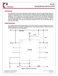
SITE MASTER 2015 INCLINOMETER SOFTWARE User's manual 30/May/2015 Version 4.0.1.0 copyright 2011-2015 @Deep Excavation LLC www.deepexcavation.com SiteMaster: Deep Excavation LLC Page 1 CONTENTS 1. Introduction .......................................................................................................................................................................... 3 2. Supported inclinometer manufacturers.................................................................................................................... 3 4. User's Interface .................................................................................................................................................................... 8 5.1. Inclinometer reading options .................................................................................................................................. 12 5.2. Create new site ............................................................................................................................................................... 17 5.3. Open site ........................................................................................................................................................................... 22 5.4. Cross-section options .................................................................................................................................................. 23 5.5. Edit site information .................................................................................................................................................... 26 5.6. Company information ................................................................................................................................................. 27 5.7. Create new inclinometer button ............................................................................................................................. 27 5.8. inclinometer settings dialog ..................................................................................................................................... 28 5.9. Project images dialog................................................................................................................................................... 32 5.10 DXF drawings and site plan view .......................................................................................................................... 37 5.10. Report options ............................................................................................................................................................. 39 6. Probe configurations ....................................................................................................................................................... 40 7. Result tables and graphs ................................................................................................................................................ 42 7.1. Site summary tab/Summary table .................................................................................................................... 42 7.2 Displacement vs. elevation graphs ..................................................................................................................... 44 8. INCLINOMETER CORRECTIONS ................................................................................................................................. 52 8.1 spiral corrections ...................................................................................................................................................... 52 8.2 rotational corrections on a reading ................................................................................................................... 55 8.3 BIAS SHIFT CORRECTIONS on a reading ......................................................................................................... 55 8.4 TRANSPOSE CORRECTIONS ON A READING ................................................................................................. 56 9. THEORETICAL BACKGROUND .................................................................................................................................... 58 10. MANUFACTURER WALKTHROUGH ....................................................................................................................... 59 10. TERMS OF USE / LICENSE AGREEMENT ............................................................................................................. 63 SiteMaster: Deep Excavation LLC Page 2 1. INTRODUCTION SiteMaster is a software program for processing and presenting inclinometer readings and results. With SiteMaster you can import any type of inclinometer data in .TXT format or use the currently available inclinometer manufacturers. SiteMaster offers a modern interactive environment that allows you to easily process and present critical information. 2. SUPPORTED INCLINOMETER MANUFACTURERS You can import any type of inclinometer data as long as the data is stored in an ordered .TXT file (see section 3). Otherwise, SiteMaster currently automatically supports Digitilt, GEOKON, ENCARDIO, RST, ITMsoil, OTR, SISGEO, SINCO, and Technopenta inclinometer raw data files. 3. Software logic SiteMaster is organized per project site. Each project contains relative information such as inclinometers, cross-sections, images etc. All project files are automatically created at a special folder within c:\\......\MyDocuments\SiteMaster Project Site (conf.xml) Images (_IMAGE directory) Cross-sections (_SECTIONS directory) Other settings (_SETTINGS directory) Inclinometers (Inclinometers directory) Inclinometer 1 (separate directory with conf.xml file) Inclinometer 2 etc (separate directory with conf.xml file) SiteMaster: Deep Excavation LLC Page 3 The following figures illustrate the sample directory files within the SiteMaster document directory. _UserProbeConfigurations: Holds the configuration files for inclinometer probes specified by the user. Figure 3.1: SiteMaster directory in Documents Figure 3.2: Project sites with SiteMaster directory in Documents (sample projects are shown) SiteMaster: Deep Excavation LLC Page 4 _IMAGES: Directory that holds the project images such as plan and key image. _SECTIONS: Directory that holds cross-sections (that can be used in any inclinometer). _SETTINGS: Directory that holds other optional settings. Inclinometers: Directory that stores all inclinometer data and configuration files. SPIRAL: Directory that stores spiral correction files (if present). conf.xml: This is the site project configuration file that holds basic project data. Figure 3.3: Sample project site directory 2762 within SiteMaster directory in Documents Figure 3.4: Images directory for sample project site 2762 SiteMaster: Deep Excavation LLC Page 5 Figure 3.5: Sections directory for sample project site 2762. Two sections are included. Figure 3.6: Settings directory for sample project site 2762. Warnings.xml file shown (this includes warning displacement levels) SiteMaster: Deep Excavation LLC Page 6 Figure 3.7: Inclinometers directory for sample project site 2762, six inclinometer directories are present. Figure 3.8: Contents of inclinometer KE202 for sample project site 2762. Conf.xml contains specific inclinometer settings, .TXT files contain individual readings. SiteMaster: Deep Excavation LLC Page 7 4. USER'S INTERFACE Figure 4.1 presents the basic user's interface. Two tabs are present in the upper part: a) General, and b) Probes. Most of the time you will only need to work on the general tab. Once a valid site is selected, you can select or modify inclinometer readings from the left vertical tab. The inclinometer axis alignment and a key plan are visible right below. A key plan can be presented only if it is included within the project and assigned to the inclinometer. The summary table presents a summary of critical inclinometer results for the last readings and also for the maximum measured displacements. Next where the "other graphs" is pointing below, you can select to view any of the available result diagrams. In the 2015 version the SitePlan view is presented in a separate popup form. Figure 4.1: General user's interface SiteMaster: Deep Excavation LLC Page 8 In the general tab the first available buttons can be used to create a new project, open an existing project, create or modify cross-sections, and edit site and company information. The remaining options include editing warning levels, adding inclinometers, site images, modifying the language, and generating reports. Button Description Launches the window for creating a new project site. Launches a dialog for opening a project (from the SiteMaster directory under MyDocuments) Launches the dialog for editing site information such as project name etc. Launches the dialog for editing your company name, engineer name. Adds a new inclinometer to the project and launches the inc Reprocesses all readings and data. SiteMaster: Deep Excavation LLC Page 9 Button Description Click on the image button to launch the Images dialog. In this dialog you can specify which images act as a general Site plan and as a key plan. Import images to site: Imports an image to the _IMAGES directory Open images folder: Opens the _IMAGES folder Import DXF site plan: Select this button to import a DXF drawing as a site plan Show Site Image: Select this option to launch a new dialog showing the site plan image (jpg or DXF) Select this option to launch a new dialog showing the site plan image (jpg or DXF) Select a cross-section to edit (when cross-sections are available) Click on the button to launch the Cross-Sections dialog. If no cross-sections are available, select "Add new section" to add a cross-section. Delete selected and Delete section options erase a crosssection from the project (permanently). Change the current language Report options button: Click on the main button to Launch the Reports dialog. Print quick report: Prints a quick summary report Print report for current inclinometer: Prints a report (according to the current format) for the currently selected inclinometer. Exporting to excel: With these two options results for either the current inclinometer or all inclinometers can be exported. This operation can take quite some time if numerous readings are to be exported, or if the PC memory limit is reached. For this reason it is recommended to export only the selected readings. SiteMaster: Deep Excavation LLC Page 10 In the probes tab, the following options are available: Button SiteMaster: Deep Excavation LLC Description Launches the dialog for creating a probe configuration file. A probe configuration file is a .xml file that is generated according to user preferences. This configuration file is visible across projects and can be used to read standard inclinometer .TXT files. Launches the dialog for defining and importing spiral correction data. Spiral corrections can be applied when the axes grooves are not aligned exactly as defined. This phenomenon can take place in deeper inclinometers. Launches the dialog for defining transpose axis correction data. Transpose corrections are for advanced users and should be handled with care. These corrections can be used in any inclinometer or any reading. Launches the dialog that regarding the software information. Page 11 5.1. INCLINOMETER READING OPTIONS The "Reading dates and options" table is generated once an inclinometer is selected and readings are available. First one has to select the applicable inclinometer from the drop down menu. . SiteMaster: Deep Excavation LLC Page 12 In the following part of the interface we are presented with the following options: Button Description Select the inclinometer to plot or modify. Launches the Zone dialog. A "Zone" is an elevation region where inclinometer results are processed. Initially each inclinometer has one zone that includes the whole inclinometer casing. This or new zones can be modified and results can only capture part of the inclinometer elevations. Launches the "Inclinometer settings dialog". Opens the folder where the raw reading text files are located. Use this dialog to add new readings for each inclinometer. These following options are used to select or deselect readings from the reading table: The Import reading button can be used to sequentially import inclinometer data files into the project (alternatively one can copy paste all files in the appropriate folder). Imported files will be renumbered in the destination folder as InclinometerName0000.extention, InclinometerName0001.extention etc. Important: Data files must be imported in chronological sequence, i.e. starting from the initial to each subsequent reading. Supported data currently include: .TXT, .CSV, .CSV by Encardio, .gkn (Geokon), rpp (RST instruments). The button can be used to delete (permanently) the selected reading. SiteMaster: Deep Excavation LLC Page 13 Figure: Import inclinometer data dialog The alpha angle is the angle from north of the A+ axis for the inclinometer. The following image illustrates a 25 deg angle from the north, and also the inclinometer shown on a key plan to the right. SiteMaster: Deep Excavation LLC Page 14 On the reading table, we have a number of options as shown below. V: Select to view reading in graphs, unselect to not display reading. Date: The date when the reading was taken. Quality: Used/Disregard options available. A used reading is utilized in time rate diagrams while a disregarded reading is not processed. Marker: The marker style used for this reading in graphs. Color: The line color used for this reading. Options: Edit. Select this button to edit further options (Reading data dialog shown below) SiteMaster: Deep Excavation LLC Page 15 The reading data dialog provides the some additional options compared to the reading table. First, the reading date can be changed manually within this dialog. The Use specific probe constant option allows the user to specify a different instrument constant for this reading. This could be used to simulate a different probe that was used in this reading (for example in case the standard probe is repaired). In tab 5, statistical results are presented for the current reading. These include the mean A and B sums and the respective standard deviations. A perfect reading would have Mean A= 0 and Mean B=0. Tab 6 includes possible corrections that can be applied to the reading (see Inclinometer corrections chapter). The 2nd tab as shown below contains a table with reading results. Cum. A and Cum. B refer to cumulative displacements in the A and B axes while Rot A. and Rot. B. present the calculated rotated displacements. Chk. A and Chk. B. are the check sums. SiteMaster: Deep Excavation LLC Page 16 The third tab (3 results in specified points) provides the ability to interpolated displacement results along different elevations (or depths) for all readings. The elevations within the included table are passed automatically to all other readings for the selected inclinometer. 5.2. CREATE NEW SITE Select the button above to create a new project site. After selecting the button the following dialog appears. On the right a list of existing projects is presented. SiteMaster: Deep Excavation LLC Page 17 The Site ID is the ID by which the project will be created in the file system. It is recommended that the ID refers to your internal project number. Otherwise, the form contains critical project information such as: Name: Project name Description: Project description Client: The client of this project Status: The project status, i.e. active, completed, etc. Within this dialog, we have the option to either select Metric or Imperial units. Please note that the raw data files and the project units have to be consistent. When the site is created, SiteMaster asks us if we want to use the project wizard: SiteMaster: Deep Excavation LLC Page 18 If we select yes, then the following dialog appears: Select Next, and in Tab 1. Inclinometer probe select the inclinometer probe manufacturer and insert the probe constant. SiteMaster: Deep Excavation LLC Page 19 Select Next, and the 2. Inclinometers tab appears. Here you can define the inclinometers and their azimuth angle to the A+ axis. Select Next, and the 3. Warning Levels tab appears. By clicking on “Edit displacement levels”, we can define various warning levels. SiteMaster: Deep Excavation LLC Page 20 Select Next, and the program takes you to the 4. Images tab. If the check buttons are selected, the program gives you the options to insert a key image and a site plan image. The key image is a small image that appears next to the inclinometer plots, while the site plan image is a larger drawing or image where the maximum inclinometer displacements can be tracked with time. The site plan image can be either a .jpg file or a DXF file if the DXF module (Plus version) is activated. The site plan can be either a DXF or a jpg. One key image can be used for all inclinometers. SiteMaster: Deep Excavation LLC Page 21 5.3. OPEN SITE The Open Project button launches the following dialog. Here we can select one of the existing (or sample) projects to open. When one selects any of the projects on the right the project info is updated. SiteMaster: Deep Excavation LLC Page 22 5.4. CROSS-SECTION OPTIONS A cross-section can be used to add a sketch of the inclinometer with current excavation levels, water elevations, and installed supports. A cross-section can be assigned to any inclinometer. Before we can edit a cross-section we will have to create a new section by selecting the option "Add new section". Then we can select the new section from the drop down menu on the left. Then by clicking on the SiteMaster: Deep Excavation LLC button we can launch the Cross Sections dialog as shown below: Page 23 In the General tab of the Cross-section dialog we can edit the section name, define if the section has a wall (as well as the wall dimensions), and define the stage levels. The following items refer to: Add new stage level: Select this button to add a new stage level (excavation status) Cross-section has wall: Select this option to include a wall within the section Ztop: Top of wall elevation in m or ft Zbottom: Bottom of wall elevation in m or ft Width: Wall width in m or ft Date: Date when this stage started Left elevation: The surface elevation immediately left of the main section axis. Right elevation: The surface elevation immediately right of the main section axis (or right of the wall). Left angle: The surface angle in degrees left of the main section axis. Right angle: The surface angle in degrees immediately right of the main section axis (or right of the wall). Use water: Option that enables the display of water elevations. Water left: The water elevation immediately left of the main section axis. Water right: The water elevation immediately right of the main section axis (or right of the wall). SiteMaster: Deep Excavation LLC Page 24 The 2nd tab Supports (tiebacks etc), allows the user to define support braces at various elevations. Data includes the support name, elevation, installation angle, support type, installation date, and removal date if specified. It is recommended that this data is added as the project construction evolves so that a complete time history is systematically created for each inclinometer. In the 3rd tab titled Boring, we can define the soil stratigraphy in terms of Top of layer elevation, layer name, layer color, and hatch style. Layers should always be defined from top to bottom. If the Use boring option is unselected then the boring will not be used. SiteMaster: Deep Excavation LLC Page 25 5.5. EDIT SITE INFORMATION This button launches the Project settings dialog as shown below. The Site ID is the ID by which the project will be created in the file system. It is recommended that the ID refers to your internal project number. Within this dialog the site ID is locked and cannot be edited. Otherwise, the form contains critical project information such as: Name: Project name Description: Project description Client: The client of this project Status: The project status, i.e. active, completed, etc. Within this dialog, we have the option to either select Metric or Imperial units. Please note that the raw data files and the project units have to be consistent. SiteMaster: Deep Excavation LLC Page 26 5.6. COMPANY INFORMATION Select this button to launch the Company info dialog. Here you can define the compay name and the engineer's name that is preparing the report. 5.7. CREATE NEW INCLINOMETER BUTTON Select this button to launch the dialog that allows the creation of a new inclinometer (as shown below). The dialog presents the list of available inclinometers (within the current site) and prompts us to enter the new inclinometer name. Once the inclinometer name is defined, press "Create new inclinometer" to generate the new inclinometer. Then the software launches the dialog that defines the specific inclinometer settings. SiteMaster: Deep Excavation LLC Page 27 5.8. INCLINOMETER SETTINGS DIALOG The inclinometer settings dialog appears when the user selects the Edit button next to the inclinometer list. The Open Folder button right next to the edit button opens the directory where inclinometer data files are stored. The Inclinometer settings dialog includes options regarding the inclinometer depth, position, casing inclination (A axis) etc. On the right side of the dialog a series of group boxes allow us to specify the inclinometer brand, assign a Cross-section to the inclinometer. The coordinate box allows the specifications of the exact elevations and inclinometer coordinates. The top elevation is utilized in all displacement-elevation graphs, while the X and Y coordinates are used when one views displacements on a plan view image (such as a project plan). The lower tabs provide a series of options for adjusting the style, base reading, and other options. SiteMaster: Deep Excavation LLC Page 28 Item Inst ID Name Date Status Type Probe constant Description Instrument ID Inclinometer name Installation date The status of the instrument (active, destroyed etc) Describes where the inclinometer is installed The inclinometer probe constant (for non digital inclinometers). Digital inclinometers do not use this value. Alpha The azimuth angle from north for the A+ axis. Note that the B+ axis is defined at A+ +90 deg (clockwise). Depth The inclinometer depth Step The probe step (between wheels). Metric probes 0.5m while US probes 0.6m or 2ft. Xpos X plan position in coordinates Ypos Y plan position in coordinates Top Elevation at top of casing Marker style The marker style used in time and polar graphs Line color The line color used in time and polar graphs Report rotated When this option is selected, the rotated displacements are reported displacements on angle on the Alpha Rotated angle (from North). Otherwise, each rotated displacement plot is reported on the maximum displacement direction (for each reading). Alpha Rotated Angle for reporting rotated displacements Include additional point at This option adds an additional point at the inclinometer base where base for zero dx displacements are assumed to be zero. Otherwise, the displacements at the first reading are taken as zero. This option is not applicable to SISGEO inclinometers. Report results with SiteMaster by default reports inclinometer readings along elevations. depths (not elevations) If this option is selected, then readings are reported vs. depth. In order to read data, the probe type must be defined for each inclinometer). As shown below, two options are available: a) Select from an already supported brand, or b) Use a custom probe file. If the option “Sum displacements from top” is selected, then the displacement at the top of the casing is assumed as zero. SiteMaster: Deep Excavation LLC Page 29 By selecting the Use a cross section option we can assign a cross section to the inclinometer graph (appears in reports). The relative x location of the inclinometer can also be specified (+ value moves inclinometer to the left, while negative to the right). There are options to also plot the excavation depth or the water table elevations on the time-displacement graphs. The base reading can be adjusted by selecting a specific reading: Base reading Graph limits on reports can also be adjusted manually as shown: A series of corrections can be applied to the selected inclinometer. These include spiral corrections, transposing the inclinometer base position, or transposing the true vertical position for a number of points. These corrections will be overwritten if the same correction type has been applied on the reading level (in other words, corrections applied at the reading level take precedence). Spiral correction options Transpose base options Transpose a number of points options SiteMaster: Deep Excavation LLC Page 30 When additional casing is added (or casing is removed), the program can automatically adjust for the elevation change. At this time the reference point is always the bottom of the base reading. Additional casing options Sisgeo inclinometers offer options to change the sign convention/direction of axes as shown below. Please refer to the dedicated SISGEO chapter within this document for further information. SiteMaster: Deep Excavation LLC Page 31 5.9. PROJECT IMAGES DIALOG The project images dialog currently allows the user to select up to two images. One image can be used to act as a general plan, while the other image can be used to act as a general key location image. Example project 2762 illustrates how these functions work. This dialog works with jpg. images only. In the general image, we can relate actual project coordinates with pixels. This image can be as large as desired. The key image should generally be a small image with size up to 200 pixels width by 160 pixels in height. SiteMaster: Deep Excavation LLC Page 32 Site plan instructions: a) First select the Site plan from image type b) Select an image from the available project images. c) Select if inclinometer drawing coordinates will be assigned using Pixel coordinates or not. d) If the actual coordinates are selected, then we need to define two points with actual coordinates on the image. This allows the program to calculate a drawing scale. To do this follow the next steps: d1) Set the first point actual coordinates in meters or feet. d2) Define the pixel location for the 1st point. To do this, click Set 1st point pixel coordinates. Then select on the image where the reference coordinates are located. d3) Define the actual pixel location for the 2nd point. d4) Define the pixel location for the 2nd point. To do this, click Set 2nd point pixel coordinates. Then select on the image where the reference coordinates are located. Once the point is selected, the image scale is automatically calculated. d5) Next we can select an inclinometer and set the coordinates on the screen by clicking on the image. See example project 2762. SiteMaster: Deep Excavation LLC Page 33 SiteMaster: Deep Excavation LLC Page 34 e) If the use pixel coordinates option is selected then we need to assign the pixel coordinates on the site plan image by 1st selecting the inclinometer, then selecting the option “Set coordinates on screen”, and last by selecting on the desired point on the image. SiteMaster: Deep Excavation LLC Page 35 Key plan instructions: A key plan is used to plot the inclinometer location in each legend key in inclinometer reports. A key plan uses only pixel coordinates to reference the location of the inclinometer. To do so, select the "Set coordinates on screen" button and select the location on the image. This will report the Xpixels and Ypixels coordinates that do not affect the actual inclinometer coordinates. SiteMaster: Deep Excavation LLC Page 36 5.10 DXF DRAWINGS AND SITE PLAN VIEW DXF drawigns can be imported in SiteMaster. Once a DXF drawing is imported as a SitePlan, we can view it from the SitePlan window. We can move around the image with the mouse, select inclinometers, as well as set the inclinometer positions on the DXF image. If a cross-section is assigned to an inclinometer then that cross-section can be seen on the left. By moving the timeline tracker on the bottom we can see how maximum displacements evolve over time on the plan. If we click on an inclinometer, then we can display a time graph showing the maximum and displacements along the x, y axes: SiteMaster: Deep Excavation LLC Page 37 Options on the left menu: a) Select inclinometer: Select which inclinometer is selected for the cross-section displacements b) Reposition inclinometer: Select this option to reposition the selected inclinometer by clicking on the screen. c) Show time line: This option displays the time line at the bottom of the dialog. d) Show cross-section: If a cross-section is assigned, then the cross-section can be displayed along with selected inclinometer displacements e) Show displacements: Select which displacements to view along the inclinometer crosssection f) Layers: Select which DXF layers are visible g) Fixed graph size: Option to control size of plotted polar displacements on site plan By right clicking on the DXF the following menu appears: Zoom to drawing: Option to refocus the image with all items included Zoom to inclinometers: Option to refocus the image along the center point of all inclinometers. Produces a smaller focused area. Inclinometer size automatic: Resizes the inclinometer sign on the image. Set Export Viewport: Option to select the viewport that can be exported as an image with the Export Image option. Once selected, we need to define with the mouse two points for defining a rectangular export area. Export Image: Select this option to export the selected export view as an image. Save State: Saves the current state of the drawing (layers, etc). SiteMaster: Deep Excavation LLC Page 38 5.10. REPORT OPTIONS Click on the previous button to launch the Report options dialog. In this dialog we can select which Report sections to include from the Available Report Sections. To add a section, select an item from Available Report Sections and drag to the Report format box. Reports can be generated either for all inclinometers or for one inclinometer. Reports can be exported to PDF or Word formats. SiteMaster: Deep Excavation LLC Page 39 6. PROBE CONFIGURATIONS Probe configurations are settings files that are visible on all SiteMaster projects. These configuration files contain settings that can be used to process inclinometer readings from any standard text file. A standard file must have the table form reading data start at a regular line number. First we have to select a sample file so that each field can be defined. To select a field, check Define and then select the item in the text file. Once an item is properly selected, the associated text will be highlighted with the same color as the field color (see following image). Only critical field items have to be selected. The number of points and the reading date must always be included. The date format is a string layout that determines how dates are written within the file. For four digit years use dd.MM.yyyy format. Select the Table start line item, to define where the table data starts. Once table data are successfully detected, the table grid is populated. Here the type of data contained in each column has to be defined. Some columns can be ignored. SiteMaster: Deep Excavation LLC Page 40 A sample probe configuration file Kerameikos is included. For each imported column, we have to define the type of data, and the if this column contains valid data or not. Crucial data must always be defined otherwise results will not be properly processed. Depth, elevation, or node must always be included. Also, A+, A-, B+, B- must also be defined. Column type/option 0: Depth 1: Elevation 2: node 3: A+ 4: A5: B+ 6: B7: Not used Description This is the depth of the reading point (from the top) This is the reading point elevation This is a reading node (1, 2, etc from the top). The depth is converted by node x inclinometer step. A+ axis reading A- axis reading B+ axis reading B- axis reading Use this option to ignore this reading column SiteMaster: Deep Excavation LLC Page 41 7. RESULT TABLES AND GRAPHS A number of result table and graphs are automatically generated by the software. These results are presented in detail in the following sections: 7.1. SITE SUMMARY TAB/SUMMARY TABLE The "Site summary" tab contains a summary of all inclinometers on site and a rotated displacement vs. time for all included inclinometers (Fig. 7.1). The summary table reports the last reading date and the last valid cumulative and rotated displacements for each inclinometer. Maximum cumulative and rotated displacements are also reported because maximum displacements can possibly occur in past dates. An inclinometer can be ignored in the report by unselecting the "Include in report" option. If a site plan is included and the inclinometers are properly positioned, then a view is generated at the "Site plan view" (Fig. 7.2). Figure 7.1: Site summary tab (select an item from Curve to move the tracker along the data). SiteMaster: Deep Excavation LLC Page 42 Figure 7.2.a: Site summary tab, site plan view with polar displacements plotted. SiteMaster also offers exciting options for reviewing results. The program offers the option to show displacements based on the available project timeline (based on first and last reading dates). By selecting the Show cross-section option, the user is presented with the capability to plot a cross-section and related inclinometer displacements next to the plan diagram. The plotted result type (cumulative, rotated, and other displacements) can be changed. Furthermore, an option to automatically show the displacement progress is available. Mouse the mouse on top of an inclinometer and click once. Then the program displays a tool tip that informs of the last valid reading that relates to the selected inclinometer (see figure 7.2.b). If we double click then the selected inclinometer settings dialog appears. SiteMaster: Deep Excavation LLC Page 43 Figure 7.2.b: Single click on a selected inclinometer (when a plan view is available) 7.2 DISPLACEMENT VS. ELEVATION GRAPHS SiteMaster generates a number of displacement graphs vs. elevation. These graphs can be seen by selecting one of the relative tabs in the main program view. Graphs include: Cumulative displacements tab: These are the total displacements from the reference reading (Fig. 7.3). Rotated tab: Rotated displacements along critical rotated axis (Fig. 7.4) Vector displacements tab: These displacements represent the resultant (absolute) movement at each point. The vector displacements are reported in the direction angle (Fig. 7.5) Vector top: This graphs presents the actual cumulative resulting displacement at each point as viewed from the top (Fig. 7.6). Last increment tab: These are the displacement changes from the last valid reading (Fig. 7.7) Time graphs tab: These are maximum displacement vs. time graphs (Fig. 7.8) Incremental graphs: These graphs show the change in the tube verticality on each reading (Fig. 7.9) Polar tab: This graph plots the evolution of the maximum polar displacement in x -y coordinates (Fig. 7.10). When more zones are available, the program offers the ability to choose which elevation zone to visualize. Velocity tab: This graph plots the displacement change rates in mm/day or inch/day for all type displacements (Fig 7.11). SiteMaster: Deep Excavation LLC Page 44 Table tab: This tab contains a table that summarizes the reading number and date. The tables also present critical check sums in the A and B axes. If the check sums are deviating significantly from zero, the program gives progressive color warnings. Check sum tab: This tab plots the Check sums in the A and B axes. Check sums can be used to check the quality of each reading (Fig. 7.12). Checks sums are the differences between the first and second inclinometer pass. A zero value indicates that the two passes agree and most likely a very good reading. Welcome tab: A tab that describes the program and simply says hello! Figure 7.3: Cumulative displacements vs. elevation SiteMaster: Deep Excavation LLC Page 45 Figure 7.4: Rotated displacements vs. elevation Figure 7.5: Vector displacements and direction (from project North) 7.6: Vector displacements top view SiteMaster: Deep Excavation LLC Page 46 Figure 7.7: Last increment vs. elevation for each selected reading SiteMaster: Deep Excavation LLC Page 47 Figure 7.8: Time graphs for current inclinometer Figure 7.9: Incremental displacements vs. elevation for current inclinometer SiteMaster: Deep Excavation LLC Page 48 Figure 7.10: Polar displacement graph for current inclinometer (and selected elevation zone) Figure 7.11: Velocity graph for current inclinometer (and selected elevation zone) SiteMaster: Deep Excavation LLC Page 49 Figure 7.12: Table data for current inclinometer. SiteMaster: Deep Excavation LLC Page 50 Figure 7.13: Check sum graphs vs. elevation for current inclinometer (and selected elevation zone) SiteMaster: Deep Excavation LLC Page 51 8. INCLINOMETER CORRECTIONS Inclinometer data might be erroneous due to various factors. Errors can be generated from systematic or random reasons. In some cases these errors need to be corrected in order to properly evaluate readings. Available correction options in Sitemaster are described in the following sections. Corrections are applied with the following sequence: a) Bias shift correction defined on probe constant units. b) Spiral corrections. c) Rotation corrections. d) Bias shift correction defined on specified displacement at a depth. Corrections should be carefully applied by experienced engineers or personnel. In general it best to apply only one type of correction to an inclinometer reading. 8.1 SPIRAL CORRECTIONS Spiral corrections may be required when the inclinometer casing grooves deviate significantly from the A-A and B-B defined axis angles with depth. In this case, the readings in A-A and B-B taken by the inclinometer are not on the original directions and need to be projected to the reported initial axes. The corrected readings are computed with the following equations: aNew = a1 * Cos(DELTA_A) + b1 * Cos(DELTA_B + 90o) bNew = a1 * Sin(DELTA_A) + b1 * Sin(DELTA_B + 90o) Where: aNew = Corrected reading in basic Alpha axis a1 = Initial reading in Alpha axis DELTA_A = Alpha angle spiral - Alpha inclinometer bNew = Corrected reading in basic Beta axis (alpha +90deg) b1 = Initial reading in Beta axis DELTA_B = Beta angle spiral - Beta inclinometer Spiral corrections can be applied either to all inclinometer readings or to a specific reading. Spiral corrections defined on a specific inclinometer reading will take precedence over spiral corrections SiteMaster: Deep Excavation LLC Page 52 The spiral corrections dialog can be launched from the Inclinometer Settings dialog, the Reading dialog, and from the "Edit spiral correction data" in the probes tab. Data are defined in terms of depth, Alpha, and Beta angle (from north). Depth data must be entered in sequence otherwise erroneous results will be produced. Select the Import readings from file button to import spiral data from a spiral data file (currently Geokon .gks and RST instruments .CSV, Sisgeo SPI, and Sisgeo TXT files are supported). From version 2.4.0.0 spiral data also includes the Operator that took the readings and an option that indicates if the angles are relative to the original azimuth or not. If this option is selected, then the tabulated angle data represent the actual angle deviation from the original axes and not true azimuth values. In this respect, the angles should be referenced to the known axis orientation which is measurable at the top of the inclinometer casing. RST files report the cumulative spiral deviation from the bottom of the inclinometer. In this case, the cumulative angular deviation is adjusted and the starting point is set at the top of the casing, as the azimuth angle is always referenced at the top. SiteMaster: Deep Excavation LLC Page 53 SiteMaster: Deep Excavation LLC Page 54 8.2 ROTATIONAL CORRECTIONS ON A READING Rotational corrections can be applied to rotate a reading by a specified angle (in radians). These corrections are applied to the A+ and B+ axis and a positive value rotates the true positive position initially back towards the vertical. 8.3 BIAS SHIFT CORRECTIONS ON A READING a) Bias shift on probe units b) Bias shift of displacements and depth Bias shift errors are usually systematic errors generated from long term use of a probe and probable misalignment due to the probe taking hits etc. With this error while a probe should give a zero reading when it is suspended vertically it instead produces a non-zero value. Bias shift corrections can be applied either a) on the probe units or b) to the obtained cumulative displacements as previously shown (Reading dialog). In sitemaster, the bias shift is applied as: a) A value = [(A+ reading) - (A-reading) + Correction] x Probe step / (2 x Probe constant) b) By defining where the cumulative displacements should pass at a specified depth (typically at a fixed zone where zero displacements are known. SiteMaster: Deep Excavation LLC Page 55 8.4 TRANSPOSE CORRECTIONS ON A READING Transpose corrections can be used to modify either the true vertical position of a reading, or change the inclination increment (in reading or displacement units) to allow adjusting for various errors. Transpose corrections are geared towards advanced users and should be handled with extreme care. a) Transpose corrections applied to true vertical position b) Transpose base correction (moves horizontally the true vertical axis on all points) c) Modify initial A or B readings (modifies the incremental displacements on a number of points) SiteMaster: Deep Excavation LLC Page 56 The button Launches the Transpose true vertical axis settings dialog as shown below. When applied as true shifts in the absolute position, the program looks to match the selected depth point and change the calculated vertical position by the specified value in A or B. These corrections can also be applied as a change to the A and B incremental displacements. Care should be taken as there is a different treatment for digital and analog probes (the following equations are also applicable to the B axis): a) For analog probes the change is calculated as: ANEW (mm or inches) = AINITIAL+ (A change x Probe constant x depth step /2) b) For digital inclinometers: ANEW (mm or inches) = AINITIAL + A change Currently, digital probes include Encardio, RSTdigital, and Automatic MM/dd/yyyy. SiteMaster: Deep Excavation LLC Page 57 9. THEORETICAL BACKGROUND This section summarizes the theoretical methods used in SiteMaster for calculating inclinometer displacements. When a reading is taken, the probe is first lowered on the 1st guide of the A axis and then on the 2nd guide of the A axis. As the probe is lifted at regular intervals, readings are taken that represent the tube inclination along the recorded axes. Theoretically the two readings should have the same absolute value but different signs. Because of imperfections the readings usually display some differences, so if we call the first set A1 and A2, then the step increment can be established as: 𝐴= 𝐴1 − 𝐴2 + 𝐶𝑅𝐴 𝐷𝑒𝑝𝑡ℎ 𝑆𝑡𝑒𝑝 2 𝑃𝑟𝑜𝑏𝑒 𝑐𝑜𝑛𝑠𝑡𝑎𝑛𝑡 Where: Depth step: Is the increment for taking readings CRA = Correction applied by user to account for errors along A axis A1 = 1st guide reading in A axis A2 = 2nd guide reading in A axis (opposite to 1st guide) Probe constant: Provided by manufacturer, usually 20000 If the probe is bidirectional then the inclinometer is taking readings along the B axis at the same time. However, as these readings are not as reliable, the probe can be lowered along the 3 rd and 4th guides along the B axis. Then the vertical increment along the B axis can be established as: 𝐵= 𝐵1 − 𝐵2 + 𝐶𝑅𝐵 𝐷𝑒𝑝𝑡ℎ 𝑆𝑡𝑒𝑝 2 𝑃𝑟𝑜𝑏𝑒 𝑐𝑜𝑛𝑠𝑡𝑎𝑛𝑡 Where: CRB = Correction applied by user to account for errors along B axis B1 = 1st guide reading in B axis B2 = 2nd guide reading in B axis (opposite to B1 guide) SiteMaster: Deep Excavation LLC Page 58 10. MANUFACTURER WALKTHROUGH Geokon adopts SiteMaster We are very proud that Geokon, a highly reputed monitoring instrumentation manufacturer has recently adopted SiteMaster as their professional standard inclinometer software program. How does it work? Create a new inclinometer, and set the inclinometer brand to Geokon. Select to import readings: Select Geokon (*.gkn), select files to import, and done. SiteMaster: Deep Excavation LLC Page 59 SISGEO Inclinometers SiteMaster supports recent and older SISGEO output file formats. The most recent format is the SISGEO 2012+ format on the standard probe options. The raw data files from SISGEO have to be first converted into readable text files before they can be imported in SiteMaster. SISGEO inclinometers use a different layout of the default guides from what is typical of other manufacturers. Guide 1 is typically assigned to the A- axis, whereas guide 2 is assigned to the A+ axis. Guides 3 and 4 are usually assigned to the B- and B+ axis respectively. The user has the option to change the assigned guides for each inclinometer, although the default values are set as -1 for each axis. The default axis arrangement can be seen below: To set the A- axis on the top set the alpha angle of the inclinometer to 180 degrees. SiteMaster: Deep Excavation LLC Page 60 Readings can be taken in different sequences as shown below: SiteMaster: Deep Excavation LLC Page 61 To setup a SISGEO inclinometer, in the inclinometer settings dialog, select the “Sisgeo (2012+ Format)”. If the 8 reading sequence is performed, then SiteMaster automatically adjusts and makes the readings. The drop down menu then selects which guide measures are considered for displacements. The software can automatically adjust if a measurement was performed by reading all guides or four. The Direction signs change were the guides 1, 3 and 2-4 are defined. If we wish to match the exact SISGEO definitions then the Alpha angle needs to be set as 180 degrees (with the A+ axis pointing south). In the default scenario, as shown below, the (1) guide is assigned to the A- axis, the (2) guide is assigned to the B- axis, the (3) guide is assigned to the A+ axis, and the (4) guide is assigned to the B- axis. These settings are demonstrated in the previous image. SiteMaster: Deep Excavation LLC Page 62 10. TERMS OF USE / LICENSE AGREEMENT This legal document is an agreement between you (the end user) and Deep Excavation. BY CONTINUING WITH/OPENING/DOWNLOADING THIS SOFTWARE PROGRAM, YOU ARE AGREEING TO BECOME BOUND BY THE TERMS OF THIS AGREEMENT, WHICH INCLUDES THE SOFTWARE LICENSE, SOFTWARE DISCLAIMER OF WARRANTY, AND HARDWARE LIMITED WARRANTY "collectively the "Agreement". This agreement constitutes the complete agreement between you and Deep Excavation. IF YOU DO NOT AGREE TO THE TERMS OF THIS AGREEMENT, DO NOT CONTINUE WITH THIS SOFTWARE PROGRAM. Promptly return or delete the software program (cd and jewel case) and other items that are part of this product to Deep Excavation, for a complete refund if a purchasing fee was charged. THIS SOFTWARE PROGRAM SITEMASTER CAN ONLY BE DOWNLOADED FROM OUR WEBSITE OR ANY OTHER OFFICIAL DISTRIBUTOR. SHOULD YOU USE A PIRATED VERSION OF THIS SOFTWARE, YOU AGREE TO BE HELD PERSONALLY LIABLE FOR DAMAGES TO DEEP EXCAVATION LLC FOR A MINIMUM AMOUNT OF US $50000 UNLESS YOU OFFICIALLY PURCHASE THE SOFTWARE FOR 3 TIMES THE OFFICIAL PRICE WITHIN 30 DAYS OF REALIZING THAT YOU PURCHASED A PIRATED VERSION. THE LICENCE APPLIES TO PURCHASHED AND FREE OF PURCHASE VERSIONS OF THE SITEMASTER SOFTWARE. LICENSE. In consideration of payment of the LICENSE fee, which is a part of the price you paid for this product, Deep Excavation, as Licensor grants to you, the LICENSEE, a nonexclusive right to use and display this copy of Deep Excavation Engineering Program, Trench, Steel-Connect, Steel Beam, Software (hereinafter referred to as "SOFTWARE" on a single COMPUTER (i.e., with a single CPU) at a single location. Any "networking", namely operating this program on a "network" is strictly forbidden. You as a Licensee are strictly forbidden to operate, utilize, transfer, distribute, connect, network, link to, attach, or operate in any manner this software on the internet, worldwide web, via email, any website, networking, any multimedia device, electronic or otherwise or any form of electronic media whatsoever. This includes but is not limited to the written materials, results, output, or resulting answers and/or printed matter without the prior written consent of Deep Excavation. Deep Excavation reserves all rights not expressly granted to LICENSEE. SOFTWARE OWNERSHIP. As the LICENSEE, you own the magnetic or other physical media on which the SOFTWARE is originally or subsequently recorded or fixed, however, Deep Excavation retains title and ownership of the SOFTWARE recorded on the original disk copy(ies) and any subsequent copies of the SOFTWARE, regardless of the form or media in or on which the original and other copies may exist. This License is not a sale of the original SOFTWARE or any copy thereof. SiteMaster: Deep Excavation LLC Page 63 COPY AND/OR MODIFY RESTRICTIONS. All Licensed Products are copyrighted and may not be further copied, without the prior written approval of Deep Excavation except that You may make one copy for backup purposes provided You reproduce and include the complete copyright notice, disclaimer, etc., on the backup copy. Any unauthorized copying is in violation of this Agreement and also a violation of the United States Copyright law. You may not use, transfer, modify, copy of otherwise reproduce the License Product, or any part of it, except as expressly permitted in this End User License Agreement. USE RESTRICTIONS. As the LICENSEE, you may physically transfer the SOFTWARE from one computer to another provided that the SOFTWARE is used on only one computer at a time. You may not electronically transfer the SOFTWARE from one computer to another over a network. You may not distribute copies of the SOFTWARE or accompanying written materials to others. You may not operate, utilize, transfer, distribute, connect, network, link to, attach, or operate in any manner this software on the internet, worldwide web, via email, any website, networking, any multimedia device, electronic or otherwise or any form of electronic media whatsoever. You may not modify, adapt, translate, reverse engineer, decompile, disassemble, or create derivative works based on the SOFTWARE. In addition, you may not modify, adapt, translate, or create derivative works based on the written materials, results, output, or resulting answers and/or printed matter without the prior written consent of Deep Excavation. RESTRICTIONS AGAINST TRANSFER. This SOFTWARE is licensed only to you, the LICENSEE, and may not be transferred to anyone without the prior written consent of DEEP EXCAVATION. Any authorized transferee of the SOFTWARE shall be bound by the terms and conditions of this Agreement. In no event may you transfer, assign, copy, rent, lease, sell, or dispose of the SOFTWARE in any manner on a temporary or permanent basis except as expressly provided herein. TERM. This End User License Agreement is effective from the date of purchase by You or granting to you of the Licensed Product and shall remain in force until terminated. You may terminate this End User License Agreement at any time by destroying the Licensed Product together with any backup copy in any form made by You or received by You. In addition, your right to use the Licensed Product will terminate if You fail to comply with any of the terms or conditions of this End User License Agreement. Upon such termination You shall destroy the copies of the Licensed Product in your possession. DISCLAIMER OF WARRANTY AND LIMITED WARRANTY THE SOFTWARE AND ACCOMPANYING WRITTEN MATERIALS (INCLUDING RESTRICTIONS FOR USE) IF ANY, ARE PROVIDED "AS IS" WITHOUT WARRANTY OF ANY KIND. FURTHER, DEEP EXCAVATION DOES NOT WARRANT, GUARANTEE, OR MAKE ANY REPRESENTATIONS REGARDING THE USE, OR THE RESULTS OF THIS USE, OF THE SOFTWARE OR WRITTEN MATERIALS IN TERMS OF CORRECTNESS, ACCURACY, RELIABILITY, CURRENTNESS, OR OTHERWISE. THE ENTIRE RISK AS TO THE RESULTS AND PERFORMANCE OF THE SOFTWARE IS ASSUMED BY YOU . SiteMaster: Deep Excavation LLC Page 64 Deep Excavation warrants to the original LICENSEE (a) the disk(s) on which the SOFTWARE is recorded to be free from defects in materials and workmanship under normal use and service for a period of sixty (60) days from the date of delivery as evidenced by a copy of the receipt. In addition, Deep Excavation hereby limits the duration of any implied warranty(ies) on the disk or such hardware to the respective period stated above. Deep Excavation's entire liability and your exclusive remedy as to the disk(s) or hardware shall be, at Deep Excavation's option, either (1) return of the purchase price or (2) replacement of the disk or hardware that does not meet Deep Excavation's Limited Warranty and which is returned to Deep Excavation with a copy of the receipt. If failure of the disk or hardware has resulted from accident, abuse or misapplication, Deep Excavation shall have no responsibility to replace the disk or hardware or refund the purchase price. Any replacement disk or hardware will be warranted for the remainder of the original warranty period or thirty (30) days, whichever is longer. WHILE DEEP EXCAVATION LLC MAKES EVERY EFFORT TO HAVE ALL SOFTWARE ERROR FREE, DEEP EXCAVATION LLC MAKES NO EXPRESSED GUARANTEE TO THE ACCURACY OF PERFORMED CALCULATIONS. THE ABOVE ARE THE ONLY WARRANTIES OF ANY KIND, EITHER EXPRESS OR IMPLIED, INCLUDING BUT NOT LIMITED TO THE IMPLIED WARRANTIES OR MERCHANTABILITY AND FITNESS FOR A PARTICULAR PURPOSE THAT ARE MADE BY DEEP EXCAVATION ON THIS PRODUCT. NO ORAL OR WRITTEN INFORMATION OR ADVICE GIVEN BY DEEP EXCAVATION, ITS DEALERS, DISTRIBUTORS, AGENTS, OR EMPLOYEES SHALL CREATE A WARRANTY OR IN ANY WAY INCREASE THE SCOPE OF THIS WARRANTY, AND YOU MAY NOT RELY ON ANY SUCH INFORMATION OR ADVICE. NEITHER DEEP EXCAVATION NOR ANYONE ELSE WHO HAS BEEN INVOLVED IN THE CREATION, PRODUCTION, OR DELIVERY OF THIS PRODUCT SHALL BE LIABLE FOR ANY DIRECT, INDIRECT, CONSEQUENTIAL, OR INCIDENTAL DAMAGES (INCLUDING DAMAGES FOR LOSS OF BUSINESS PROFITS, BUSINESS INTERRUPTION, LOSS OF BUSINESS INFORMATION, AND THE LIKE) ARISING OUT OF THE USE OF OR INABILITY TO USE SUCH PRODUCT EVEN IF DEEP EXCAVATION HAS BEEN ADVISED OF THE POSSIBILITY OF SUCH DAMAGES. IN ALL CASES A LICENCED PROFESSIONAL ENGINEER SHALL APPROVE AND STAMP ANY RESULTS BY D.E.E.P. AND THAT ENGINEER IS ULTIMATELY RESPONSIBLE FOR ANY CONSEQUENCES OR MISUSE OF THE SOFTWARE. This Disclaimer of Warranty and Limited Warranty is governed by the laws of the State of New York. Should you have any questions regarding this agreement please email: Deep Excavation, [email protected] SiteMaster: Deep Excavation LLC Page 65