1
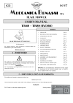
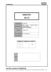
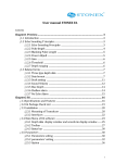
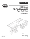
INSTALLATION AND
OPERATING MANUAL
ELECTRONIC PLATFORMS
ET – EL – ES
SERIES
ET-EL-ES_11.10_EN
ET – EL - ES series
ET-EL-ES_11.10_EN
INDEX
IMPORTANT WARNINGS ..................................................................................................................... 3
1 INTRODUCTION................................................................................................................................. 4
1.1 ET/EL TECHNICAL SPECIFICATIONS ........................................................................................ 4
1.2 ES TECHNICAL SPECIFICATIONS ............................................................................................. 5
2 INSTALLATION OF THE ET / EL / ES PLATFORMS ........................................................................ 5
2.1 UNPACKING THE PRODUCT ...................................................................................................... 5
2.2 INSTALLATION ON THE FLOOR AND CONNECTION OF THE PLATFORM ............................. 5
2.3 FLUSH-FLOOR INSTALLATION AND CONNECTION OF THE PLATFORM ............................... 6
3 CALIBRATION ................................................................................................................................... 7
4 MAINTENANCE AND REPAIRS ........................................................................................................ 8
4.1 TO OBTAIN THE BEST PERFORMANCE .................................................................................... 8
4.2 BREAKDOWNS AND OVERLOADS ............................................................................................ 8
5 TRANSPORTATION OF THE PLATFORM ........................................................................................ 8
6 DRAWINGS AND CONNECTION DIAGRAMS .................................................................................. 9
6.1 ET PLATFORM – FLOOR INSTALLATION................................................................................... 9
6.2 ET PLATFORM – FLUSH TO FLOOR INSTALLATION .............................................................. 10
6.3 EL PLATFORM – FLOOR INSTALLATION ................................................................................. 11
6.4 EL PLATFORM – FLUSH TO FLOOR INSTALLATION .............................................................. 12
6.5 ES PLATFORM – FLOOR INSTALLATION ................................................................................ 13
6.6 ES PLATFORM – FLUSH TO FLOOR INSTALLATION .............................................................. 15
6.7 MOUNTING FRAME FOR FLUSH FLOOR INSTALLATION OF THE PLATFORM .................... 17
7 INSTRUCTIONS FOR EQUALIZING THE ET / EL / ES PLATFORMS ............................................ 18
8 SHIELDED CABLE FOR CONNECTION OF JUNCTION BOX (JBOX) TO THE INDICATOR ....... 19
WARRANTY ........................................................................................................................................ 20
2
ET – EL - ES series
ET-EL-ES_11.10_EN
IMPORTANT WARNINGS
Make sure the following conditions are met:
- Flat, level, stable support surface isolated from vibrations, dust, and corrosive vapors.
- Moderate temperature and humidity (15-30°C and 40-70%). No large air draughts.
- Main power supply restricted to within + 10% ÷ - 15% of the rated voltage.
- Adjust the feet of the platform until the air bubble level is centered.
-Temperature and humidity moderated (do not expose to direct light of the sun, or near a source
of heat).
- Floor hardness of at least 100 kg/cm2.
Make sure the platform is level trough the feet and the air bubble (see “INSTALLATION OF THE ET /
EL / ES PLATFORMS”).
Do not weld, perforate or modify the structure without consulting the reseller. If it is damaged or
tampered with the warranty conditions will be annulled.
If the place of use is a humid or wet environment, the installation must be carried out in such a way so
that water stagnation and/or scraps under the structure are avoided.
The platform must be connected to a weigh indicator using the fitted cable, following the indicator’s
instructions.
Do not step, crush or expose to sunlight the connecting screen cable.
YOU NEED TO GROUND the metallic structure of the platform using the appropriate plug, which
has this symbol
, especially if you need to weigh materials that, while handled, can cause
electrical discharges (dust, plastic materials, etc.). If there are any doubts, consult the reseller.
DO NOT INSTALL IN HAZARDOUS ENVIRONMENTS.
(unless specifically made for this use)
Do not use solvents when cleaning.
3
ET – EL - ES series
ET-EL-ES_11.10_EN
1 INTRODUCTION
All weighing modules are built with high quality materials and are calibrated in such a way which
guarantees full reliability and weighing accuracy that will lasts in time. The measuring elements are 4
load cells, produced in conformance to the OIML R60 standards.
The ET/EL/ES platforms have equalized load cells, connected to each other through an IP67 junction
box fitted with a 6-pole shielded cable 5 meters long used for the connection to the weight indicator.
Every weighing module is built and engineered to guarantee a uniform detection of the load on the load
cell weighing modules, even in adverse environment conditions.
The ET, EL and ES electronic platforms are built in such a way so that they can be used in various
industrial applications (simple weighing, batching, belt weighing, etc.). With a weight capacity ranging
from 300 kg to 10.000 kg, they also permits a wide range of applications (see TABLE OF ET/EL/ES
PLATFORM VERSIONS available at www.diniargeo.com).
The platforms are built to perform efficiently in any type of environment. They are protected from a
STATIC overload of over 200% of the nominal platform capacity.
The ET platforms can be of two types:
NORMAL
Structure made of tubular steel, oven fire painted light blue RAL 5007, and removable loading top in
galvanized sheet iron (also available in AISI 304 stainless steel). The measuring element consists of
four shear-beam IP68 stainless steel direct load cells which are also OIML R60 approved.
STAINLESS STEEL
Structure and loading top in AISI 304 stainless steel. The measuring element consists of four shearbeam IP68 stainless steel load cells which are also OIML R60 approved.
The EL platforms have a structure made of tubular steel and with a non-removable loading top made
of sheet steel; everything is oven fire painted light blue RAL 5007. The measuring element consists of
four shear-beam IP68 stainless steel load cells which are also OIML R60 approved.
The ES platforms have a structure made of steel and with a non-removable loading top made of sheet
steel; everything is oven fire painted light blue RAL 5007. The measuring element consists of four offcenter IP68 stainless steel load cells which are also OIML approved.
1.1 ET/EL TECHNICAL SPECIFICATIONS
Load cells
Max power supply tension tolerated
Nominal output (nickel-plated steel cell)
Combined error
Compensated temperature range
Operating temperature range
Cell resistance:
Input
Output
SHEAR BEAM
15 VDC
2 or 3 mV/V +/- 0,25% (depending on the model)
< 0,03 % FSO
-10°C / +40°C
-18°C / +65°C
350 Ohm *
350 Ohm *
* or 1000 Ohm depending on the model
4
ET – EL - ES series
1.2 ES TECHNICAL SPECIFICATIONS
Load cells
Max power supply tension tolerated
Nominal output (aluminum alloy cell)
Combined error
Compensated temperature range
Operating temperature range
Cell resistance:
Input
Output
ET-EL-ES_11.10_EN
OFF-CENTER
15 VDC
2 mV/V +/- 10%
< 0,03 % FSO
-10°C / +40°C
-10°C / +50°C
300 Ohm *
300 Ohm *
* or 500 Ohm depending on the model
2 INSTALLATION OF THE ET / EL / ES PLATFORMS
The weighing module must be connected to its appropriate weight indicator by using the cable coming
from the junction box.
The indicator, connected to the platform, can not be calibrated if not powered.
It is the customer’s responsibility to prepare and calibrate the indicator.
For any further detail, refer to the technical manual, supplied with the indicator.
If the ET / EL / ES platform is supplied with the indicator, the calibration is not necessary; otherwise
follow the instructions in the paragraph “CALIBRATION”.
2.1 UNPACKING THE PRODUCT
a) Unpack the product.
b) Check if any damage was caused by the transportation and make sure that there are:
1 base, 1 plate, 4 adjustable feet, 1connection cable and 1 installation manual.
2.2 INSTALLATION ON THE FLOOR AND CONNECTION OF THE PLATFORM
MAKE SURE TO FOLLOW THE WARNINGS ON PAGE 3.
Refer to fig.1 (paragraph 6.1), fig.3 (paragraph 6.3) or fig.5-6 (paragraph 6.5) when positioning the
platform on the floor.
Follow this procedure when positioning the platform:
a) Screw completely the feet (2) on the cells (3) by lifting the side of the platform. NEVER UNLOOSE
THE BOLTS (4).
b) Level the platform by adjusting the adjustable feet (2) until the bubble (5) is in the centre of the
level. The stability of the platform is very important.
All the corners MUST REST IN A UNIFORM WAY. Carefully check that all feet fully rest on the
ground and that the platform, loaded on the corner, is not unstable (if a corner is not resting on the
ground its relative foot is easier to turn).
5
ET – EL - ES series
ET-EL-ES_11.10_EN
Furthermore, in order to maintain the platform performance, the feet must be adjusted in order that
the height (H) of the platform corresponds to that shown in the table available at
www.diniargeo.com.
In no circumstance, the limits shown in the drawing below must be exceeded.
K
K
K <0
c) Open the trapdoor on the ET platform (located on the load surface, detail 9 fig.1) or the drawer on
the EL platform (located on the side of the platform, detail 9 fig.3), by removing its screws (10), and
pass the screened cable connected to the junction box (detail 6, fig.1 and fig.3), through the hole
(7) under the platform and connect it to the indicator.
On the ES platform connect the screened cable (detail 8, fig.5) to the indicator.
The cable must be free, so that the resistances are not energized, which could alter the
measurement. Refer to chapter “SHIELDED CABLE FOR CONNECTION OF JUNCTION BOX
(JBOX) TO THE INDICATOR” for cables color and function.
d) Reposition the trapdoor on the ET platform (9 fig.1) or the drawer on the EL platform (9 fig.3) in its
place (1) using its screws (10).
2.3 FLUSH-FLOOR INSTALLATION AND CONNECTION OF THE PLATFORM
All the ET, EL and ES series platforms can be embedded for a flush floor use.
The pit should be made with the measurements suitable to the chosen platform model according to
what it is shown in the drawings available at www.diniargeo.com.
For a flush to floor installation of the platform, you need to position in the pit the PIT PROFILE FRAME
and the FIXING PLATES (refer to paragraph 6.2, 6.4 or 6.6, and paragraph 6.7).
Dig up the pit and wall up the PROFILE FRAME as described in the drawings available at
www.diniargeo.com.
MAKE SURE TO FOLLOW THE WARNINGS ON PAGE 3.
Refer to fig.2 (paragraph 6.2), fig.4 (paragraph 6.4) or fig.6 (paragraph 6.6) when positioning the
platform on the floor.
Follow this procedure when positioning the platform:
a) Screw the feet (2) on the cells (3) lifting the side of the platform. NEVER UNLOOSE THE BOLTS
(4).
b) Install the FIXING PLATES on the angles of the pit and lower the platform. Make sure to leave a 5
mm space around the loading top (once it is repositioned), so that it will not touch the pit border
6
ET – EL - ES series
ET-EL-ES_11.10_EN
frame.
c) Remove the plate (ET versions) or the platform (EL and ES versions) from the pit, making sure that
the fixing plates are not moved.
d) Tighten the fixing bolts of the plates in order to maintain the platform in the correct position.
e) Open the trapdoor on the ET platform (located on the load surface, detail 9 fig.2) or the drawer on
the EL platform (located on the side of the platform, detail 9 fig.4), by removing its screws (10), and
pass the screened cable connected to the junction box (detail 6, fig.2 and fig.4), through the hole
(7) under the platform, making it go through its piping (see drawing available at
www.diniargeo.com) and connect it to the indicator.
On the ES platform, pass the screened cable (detail 8, fig.7) through its piping (see drawing
available at www.diniargeo.com) and connect it to the indicator.
The cable must be free, so that the resistances are not energized, which could alter the
measurement. Refer to chapter “SHIELDED CABLE FOR CONNECTION OF JUNCTION BOX
(JBOX) TO THE INDICATOR” for cables color and function.
f) Reposition the trapdoor on the ET platform (9 fig.2) or the drawer on the EL platform (9 fig.4) in its
place (1) by using its screws (10).
g) Reposition the platform into the pit.
h) Adjust the feet (2) until the bubble (5) is in the centre of the level, making sure that the platform
rests on all 4 feet.
3 CALIBRATION
a) If platform and indicator are not supplied together, follow the specific instructions of the indicator to
make the scale operate and then follow the steps b), c), d) and e).
b) The calibration should be done 15 minutes after the indicator has been turned on.
c) Calibrate the indicator by following the instructions on its technical manual.
d) Check the corners (see the paragraph “INSTRUCTIONS FOR EQUALIZING THE ET / EL / ES
PLATFORMS”) of the platform by positioning on these (one at a time) a weight equal to
of the
indicator’s maximum capacity. Check that the error is not greater than + / - 2 divisions and if this is
not the case, contact the RESELLER.
e) Using a reference weight, check the zero and the full-scale capacity.
7
4 MAINTENANCE AND REPAIRS
4.1 TO OBTAIN THE BEST PERFORMANCE
-
One should keep the platform clean. If dirt and dust accumulate on the platform one should clean
it with a damp cloth or with the common cleaning products (do not use SOLVENTS and
ACIDS).
- Avoid platform collisions because this could cause serious damages.
4.2 BREAKDOWNS AND OVERLOADS
If you think the platform is broken or damaged disconnect it in a permanent way. Do this if the
platform:
- appears to be damaged;
- does not work;
- has been loaded more than its tolerable limits (which could happen during the transportation or
at time of storage).
5 TRANSPORTATION OF THE PLATFORM
To pack the platform follow the procedure below:
a) turn off the indicator;
b) disconnect the platform’s indicator;
c) remove the feet.
ET – EL - ES series
ET-EL-ES_11.10_EN
6 DRAWINGS AND CONNECTION DIAGRAMS
Drawings available at: www.diniargeo.com
6.1 ET PLATFORM – FLOOR INSTALLATION
LOAD
SURFACE
LOAD
SURFACE
SHIELDED CABLE
TO INDICATOR
GROUND PLUG
Fig. 1
9
ET – EL - ES series
ET-EL-ES_11.10_EN
6.2 ET PLATFORM – FLUSH TO FLOOR INSTALLATION
ANCHOR
PLATE
LOAD
SURFACE
PIT FRAME
PIT FRAME
SCREENED CABLE TO
THE INDICATOR
Fig.2
10
ET – EL - ES series
ET-EL-ES_11.10_EN
6.3 EL PLATFORM – FLOOR INSTALLATION
LOAD
SURFACE
1
GROUND PLUG
SHIELD CABLE
TO INDICATOR
Fig. 3
11
ET – EL - ES series
ET-EL-ES_11.10_EN
6.4 EL PLATFORM – FLUSH TO FLOOR INSTALLATION
ANCHOR
PLATE
LOAD
SURFACE
1
PIT FRAME
SHIELD CABLE
TO INDICATOR
GROUND PLUG
Fig. 4
12
ET – EL - ES series
ET-EL-ES_11.10_EN
6.5 ES PLATFORM – FLOOR INSTALLATION
6
7
LOAD
SURFACE
1
3
4
9
10
SHIELDED
CABLE TO
INDICATOR
GROUND
PLUG
Fig.5
13
ET – EL - ES series
ET-EL-ES_11.10_EN
5
Fig.6
14
ET – EL - ES series
ET-EL-ES_11.10_EN
6.6 ES PLATFORM – FLUSH TO FLOOR INSTALLATION
3
LOAD SURFACE
1
4
6
7
SHIELDED
CABLE TO
INDICATOR
GROUND
PLUG
Fig.7
15
ET – EL - ES series
ET-EL-ES_11.10_EN
5
Fig.8
16
ET – EL - ES series
ET-EL-ES_11.10_EN
6.7 MOUNTING FRAME FOR FLUSH FLOOR INSTALLATION OF THE PLATFORM
POSITION
1
2
3
4
5
6
7
DESCRIPTION
“L” PROFILE SECTION
“L” PROFILE SECTION WITH FEET
FOOT CENTERING PLATE
Ǿ 10 WIDE BAND WASHER
M10 SELFBLOCKING NUT
Ǿ 8 WASHER
M8X20 HEXAGON HEADED BOLT
QUANTITY
2
2
4
8
8
8
8
WARNING
AFTER HAVING MOUNTED, THE INSIDE ANGLES OF THE FRAME SHOULD BE AT 90°. IF THIS IS NOT SO MAKE SURE THAT THE
INSTALLATION HAS BEEN MADE CORRECTLY AND THAT NO PARTS ARE DAMAGED.
17
ET – EL - ES series
ET-EL-ES_11.10_EN
7 INSTRUCTIONS FOR EQUALIZING THE ET / EL / ES PLATFORMS
1. Make 20 turns (clockwise) of the screws of all the “T” trimmers in order to have the maximum
signal on all the cells.
EQUALIZATION BOARD
T
2. Carry out the calibration with mass in the central point (i.e.: scale’s full scale capacity).
3. Put the indicator in visualization x 10 mode.
4. Place the sample weight (about 1/3 of the capacity) alternatively on each of the four angles of
the platform “1, 2, 3, 4” and identify the cell which shows the lowest weight.
ET/EL PLATFORM CELL LAY-OUT
ES PLATFORM CELL LAY-OUT
3
2
3
2
4
1
4
1
LEVEL
LEVEL
5. Adjust the trimmers of the remaining 3 cells so that all three display the same weight as the
cell with the lowest weight; do as follows:
18
ET – EL - ES series
ET-EL-ES_11.10_EN
a. Position the sample weight on the angle corresponding to the cell with the greatest
signal.
b. Turn (counter-clockwise) the screw of the “T” trimmer of the corresponding cell until
the weight equal to that of the cell with the lowest signal is displayed.
c. Repeat steps “a” and “b” for the remaining two angles.
6. Check again making sure that on all four angles the same weight is displayed, otherwise
adjust the trimmers of the single cells as described in points 4 and 5.
7. Once again calibrate the scale.
Notes:
- So that the equalization is carried out well, it is advisable to use a small-sized sample weight
having a value which is about 1/3 of the capacity in order to concentrate the load on each single
cell; the equalization can be considered satisfactory if the weights displayed differ of about 1
division.
- In weighing systems for hazardous areas, special junction boxes may be used. The equalization
described in this manual is relative to the standard junction box.
8 SHIELDED CABLE FOR CONNECTION OF JUNCTION BOX (JBOX) TO THE
INDICATOR
EXCITATION +
SENSE +
EXCITATION SENSE SIGNAL +
SIGNAL EARTH BRAIDING
Brown
Green
Grey
White
Pink
Yellow
Orange
The cable that comes out from the indicator should be connected to the equalization board inside
the junction box.
It has 4 wires, whose meaning is described in the table:
- Brown and Green wires, together on the same prod, connected to the + of the junction board.
- Grey and White wires, together on the same prod, connected to the – of the junction board.
In case the platform is supplied without the indicator, the end of the cable to connect to the indicator
has 6 wires whose meaning is shown in the above table.
19
ET – EL - ES series
ET-EL-ES_11.10_EN
WARRANTY
The TWO-YEARS warranty period begins on the day the indicator
is delivered and covers spare parts and labour if the
INSTRUMENTS are returned with prepaid shipping to the
DEALER and if the breakdowns are not caused by the customer
(i.e. improper use) or during the transport.
If on site service is requested (or is necessary) the customer will
be responsible for all of the service technician’s costs: travel time
and expenses plus room and board (if any).
The customer pays for the shipping costs (both ways), if the
instrument is shipped to DEALER or manufacturer for repair.
The WARRANTY IS VOIDED if breakdowns happen because
repairs have been made by unauthorized personnel or due to
connections to equipment installed by others or incorrect
connection to the power supply.
This warranty DOES NOT PROVIDE for any compensation for
damages (indirect or direct) which may cause partial or complete
failure of the instruments or systems sold, even if still in the
warranty period.
AUTHORIZED SERVICE CENTER STAMP
20