1
US008421402B2
(12) United States Patent
(10) Patent No.:
Jang
(54)
(45) Date of Patent:
METHOD AND APPARATUS FOR
(58)
PROVIDING CHARGING INFORMATION
REGARDING PORTABLE TERMINAL WITH
SOLAR CELL
(75)
Inventor:
See application ?le for complete search history.
(56)
References Cited
U.S. PATENT DOCUMENTS
5,937,229
A
*
5,939,855 A *
(73) Assignee: Samsung Electronics Co., Ltd.,
Samsung-ro, Yeongtong-gu, SuWon-si,
Gyeonggi-do (KR)
Notice:
Apr. 16, 2013
Field of Classi?cation Search ................. .. 320/101
Jin Yeoul J ang, Gyeongsangbuk-do
(KR)
(*)
US 8,421,402 B2
6,094,540 A
*
8/1999
Walgrove et a1.
......
. . . ..
8/1999 Proctoret a1. .
7/2000
Kikuchi ........... ..
399/66
320/104
.. 396/304
2004/0133300 A1*
7/2004 Tsuboi et a1.
700/195
2008/0100258 A1*
5/2008
320/101
2009/0320827 A1 *
12/2009
Ward ............... ..
Thompson et a1. ......... .. 126/576
Subject to any disclaimer, the term of this
patent is extended or adjusted under 35
* cited by examiner
U.S.C. 154(b) by 320 days.
Primary Examiner * Arun Williams
(74) Attorney, Agent, or Firm * Cha & Reiter, LLC
(21) Appl.No.: 12/777,781
(22) Filed:
(57)
ABSTRACT
A method and apparatus provides charging information
May 11, 2010
(65)
regarding devices such as a portable terminal With a solar cell.
Prior Publication Data
US 2010/0289446 A1
(30)
The solar cell charges the battery of the portable terminal With
the highest charging ef?ciency at an optimal charging angle.
The optimal charging angle is determined according to the
Nov. 18,2010
Foreign Application Priority Data
location information regarding the portable terminal and time
information. When the solar cell performs a charging process
May 12, 2009
Int. Cl.
H02] 7/00
H01M 10/44
H01M 10/46
(52) US. Cl.
(KR) ...................... .. 10-2009-0041392
provides a user With an average charging ef?ciency and the
help containing a user’s manual of the solar cell. The average
(51)
USPC
With the highest charging ef?ciency, the portable terminal
(2006.01)
(2006.01)
(2006.01)
........................................................ ..
charging e?iciency is determined according to environmental
conditions, such as temperature, humidity, Weather condi
tions, etc.
320/101
19 Claims, 5 Drawing Sheets
US. Patent
Apr. 16,2013
Sheet 1 015
US 8,421,402 B2
FIG. 1
100
W
130
If
DISPLAY UNIT
110
HF COMMUNICATION
CONTROLLER
V
CHARGING UNIT
8
160
A
>
V
STORAGE UNIT
US. Patent
Apr. 16,2013
Sheet 2 of5
US 8,421,402 B2
FIG. 2
6U
30 o
US. Patent
Apr. 16,2013
Sheet 3 of5
US 8,421,402 B2
FIG. 3
I
START
I
II
EXECUTE NEW FOR
PROVIDING CHARGING INFORMATION
I
N0
$3011
\1 I
PERFORM CORRESPONDING
FUNCTION
M8301
8303
COMMAND F0
CALCULATING OPTIMAL CHARGING
ANGLE INPUT?
IDENTIFY LOCATION INFORMATION
AND TIME INFORMATION
“#3305
I
CALCULATE INCIDENT ANGLE
ACCORDING TO SOLAR ALTITUDE
M8307
II
CALCULATE OPTIMAL CHARGING ANGLE
M8309
II
OUTPUT OPTIMAL CHARGING
ANGLE AND DIRECTION
I
END
"V3311
US. Patent
Apr. 16,2013
Sheet 4 of5
US 8,421,402 B2
FIG. 4
I
sIIIIII
)
II
ACTIVATE CHARGING FUNCTION
USING soIIIII CELL
~84l11
I
IDENTIFY FIRST CHARGING EFFICIENCY
@5403
I
RECEIVE INFORMATION REGARDING
TIME, LOCATION, AND ENNIININIIIENI
M3405
II
SEARCH FOR SECCND CHARGING EFFICIENCY \/S4[]7
sm 1
IHST GHAHGIN
EFFICIENCY -. SECOND CHARGING
A
OUTPUT ALERT MESSAGE
'8'
YES
‘
OUTPUT OPTIMAL CHARGING ANGLE
ANI] DIRECTION INFORMATION
sins
f"
U.S. Patent
Apr. 16, 2013
Sheet 5 0f 5
US 8,421,402 B2
FIG. 5
510
sin
‘IT-III
IIl?i
'IZIII
I. BIUEIGGIIH
Am
.
A
2.
. 1mmII
3. HELP
IBackI
{Q}
»
\\%3[] c
IBackI
Am
1-
Am
‘ '
EFFICIENCY
|0K|
Tull
‘Ii-III
AVERAGE GHAHGIIIG
2. IIIIIGE HEGGHIJIIIG
|0K|
52H
OPTIMAL GHAHGIIIG
ANGLE
"
/
Tull
ABE
WEATHER
4HAIIIIIIG>
HUMIDITY
4 HIGH >
TEMPEHATUHH 20°C }
AVERAGE
EFFICIENCY
IUmA/h
3
550
WJVYH
11
N
ND
1"
US 8,421,402 B2
1
2
METHOD AND APPARATUS FOR
PROVIDING CHARGING INFORMATION
REGARDING PORTABLE TERMINAL WITH
SOLAR CELL
SUMMARY OF THE INVENTION
The present invention has been made to provide a method
and apparatus that provides charging information to optimiZe
the charging e?iciency When a portable terminal charges its
battery using a solar cell.
CLAIM OF PRIORITY
In accordance With an exemplary embodiment of the
present invention, the present invention provides an apparatus
for providing charging information to a portable terminal,
preferably including a solar cell, an RF communication unit,
This application claims the bene?t of priority under 35
U.S.C. §l 19(a) from Korean patent application No. 10-2009
0041392 ?led in the Korean Intellectual Property Of?ce on
a controller, a storage unit, and a display unit. The solar cell
converts solar energy into electricity. The RF communication
May 12, 2009, the entire disclosure of Which is hereby incor
porated by reference.
unit receives location information regarding the portable ter
minal and time information. The controller calculates an opti
BACKGROUND OF THE INVENTION
mal charging angle Where the position of the solar cell permits
the highest charging ef?ciency according to the location
1. Field of the Invention
information and time information. The storage unit stores
The present invention relates to battery charging technol
average charging ef?ciency information generated as average
charging e?iciencies, Wherein the solar cell charges a battery
ogy. More particularly, the present invention relates to a
method and apparatus that provides charging information to
optimiZe the charging ef?ciency When a portable terminal
changes its battery using a solar cell.
2. Description of the Related Art
With the development of mobile communication technol
ogy, portable terminals noW provide a variety of optional
20
25
functions, such an MP3 player function, a mobile broadcast
camera function, etc. A signi?cant aspect of operating por
table terminals providing such various functions is poWer
usage, particularly so as not to deplete the batteries so as to 30
hinder their use. In recent years, portable terminals have
attempted to charge their battery by utiliZing solar energy in
solar cell, including: receiving location information regard
ing the portable terminal and time information; and output
ting the charging information corresponding to the received
location information and time information, Wherein the
charging information includes at least one of an optimal
35
provide heat and light. For example, a solar heating technol
ogy refers to a technology that heats Water using the Sun’s
solar energy through housings that transfer heat to the Water.
A sunlight use technology also refers to a technology that
converts the Sun’s light to the electricity and drives a variety
charging angle and the average charging ef?ciency. The aver
age charging e?iciency is acquired at the calculated optimal
charging angle and a particular environmental condition.
In accordance With another exemplary embodiment of the
present invention, the present invention provides a method for
providing charging information in a portable terminal With a
receiving function, a moving image playback function, a
order to overcome the limitation regarding the battery use
time.
Solar energy technology uses the Sun’s energy and light to
on the average at the optimal charging angle, and Which are
classi?ed according to a preset classi?cation condition. The
display unit displays at least one of the calculated optimal
charging angle Wherein the solar cell When positioned at the
optimal charging angle performs a charging process With a
highest charging e?iciency, and an average charging e?i
ciency at the optimal charging angle.
BRIEF DESCRIPTION OF THE DRAWINGS
40
of devices, etc., using the electricity. Solar energy is an inex
The above and other exemplary aspects, features and
advantages of certain exemplary embodiments of the present
haustible and harmless energy resource. That is, solar energy
does not cause pollution to generate electricity, such as air
invention Will become more apparent from the folloWing
pollution, noise pollution, greenhouse gases, vibration, etc.
45
Solar energy can be used in virtually any area Where the
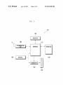
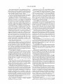
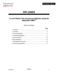
FIG. 1 is a schematic block diagram illustrating a portable
terminal With a solar cell according to an exemplary embodi
sunlight falls. Solar energy technology has recently been
applied to portable terminals to charge theirbattery With solar
ment of the present invention;
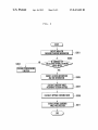
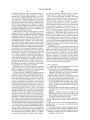
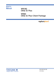
FIG. 2 is a vieW that illustrating a method for calculating an
energy. HoWever, portable terminals adapted to use a conven
tional solar energy charging method have many disadvan
50
can be so loW that a user cannot depend on being able to
exemplary embodiment of the present invention;
charge the battery.
solar energy charging process for the same amount of time
can have very different levels of charge, particularly if the
portable terminals are exposed to different external environ
mental conditions, such as different Weather conditions and
different intensities of sunlight. The result is that as the bat
55
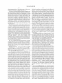
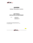
FIG. 4 is a How chart providing an operational example of
a method for providing charging information, according to
another exemplary embodiment of the present invention; and
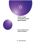
FIG. 5 illustrates screens that shoW a display menu for
providing charging information, according to an exemplary
60
teries can be charged With different amounts of charge even to
the same device, With such dependence on external condi
tions the users cannot knoW Whether the portable terminals
are charging the battery With an optimal ef?ciency, or hoW
long it Would take on a given day to charge the battery back to
maximum poWer, for example.
optimal charging angle, according to an exemplary embodi
ment of the present invention;
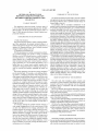
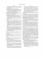
FIG. 3 is a How chart providing an operational example of
a method for providing charging information, according to an
tages in that their battery charging e?iciency depends on the
Weather conditions, time, and the sunlight intensity, and thus
For example, although the portable terminals utiliZing a
description taken in conjunction With the accompanying
draWing, in Which:
embodiment of the present invention.
DETAILED DESCRIPTION
Hereinafter, exemplary embodiments of the present inven
65
tion are described in detail With reference to the accompany
ing draWings. Detailed descriptions of Well-known functions
and structures incorporated herein may be omitted to avoid
US 8,421,402 B2
3
4
obscuring appreciation of the subject matter of the present
?eld, but the auxiliary carrier, generated by the diffusion, is
invention by a person of ordinary skill in the art.
The terms or Words described in the present description and
moved to the other type of semiconductor. Therefore, the
diffusion process causes the mobility of carriers, and thus the
charge balance in a stable state is broken. This instability
the claims should not be limited by a general or lexical mean
ing, instead should be analyZed as a meaning and a concept
through Which the inventor de?nes and describes the present
invention at his most effort, to comply With the idea of the
As described above, the solar cell 150 preferably operates in
present invention. Therefore, one skilled in the art Will under
this manner. A plurality of solar cells is connected in serial or
stand that the exemplary embodiments disclosed in the
description and con?gurations illustrated in the draWings are
parallel to convert the sunlight to electricity. The solar cell
only preferred exemplary embodiments, and there are various
modi?cations, alterations, and equivalents thereof the exem
plary embodiments at the time of ?ling this application that
opaque. In an exemplary embodiment of the present inven
tion, the solar cell 150 is installed to the body of the portable
terminal 100. If the portable terminal 100 has a cover, the
causes a potential difference. The potential difference causes
an electromotive force at both ends of the p-n junction diode.
150 may be formed so as to be transparent, translucent, or
are Within the spirit of the invention and the scope of the
solar cell 150 may be formed to be translucent or opaque.
appended claims.
In the folloWing description, although the portable terminal
multimedia devices, and their applications, such as, a navi
Furthermore, if the solar cell 150 is installed in/on the display
unit 130, the solar cell 150 may be implemented to be opaque.
The solar cell 150 outputs current, Where the amount of
output current varies according to the sunlight intensity. In
general, the solar cells for the portable terminals may output
0~l 50 mA according to the intensity of sunlight. The output
current of the solar cell 150 ?oWs into the charging unit 160
and then is used to charge the battery 170 of the portable
gation terminal, a digital broadcast receiver, a personal digital
terminal 100.
according to the present invention is described based on a
example of a portable terminal equipped With a solar cell, a
person of ordinary skill in the art Will understand and appre
ciate that the portable terminal is merely representative of
virtually any type of information communication devices,
20
assistant (PDA), a smart phone, a portable multimedia player
(PMP), an international mobile telecommunication 2000
(IMT-2000) terminal, a code division multiple access
(CDMA) terminal, a Wideband code division multiple access
25
the charging unit 160 also receives electrical poWer from an
external adapter and then charges the battery 170 With the
received electrical poWer. The charging unit 160 may further
(WCDMA) terminal, a global system for mobile communi
cation (GSM) terminal, a universal mobile telecommunica
tion service (UMTS) terminal, etc.
include, for example, an overcharge protection circuit.
30
FIG. 1 is a schematic block diagram illustrating a portable
terminal 100 With a solar cell according to an exemplary
embodiment of the present invention, and FIG. 2 provides an
operational example of a method for calculating an optimal
charging angle, according to an exemplary embodiment of
the present invention.
Referring noW to FIGS. 1 and 2, the portable terminal 100
preferably includes a controller 110, a storage unit 120, a
display unit 130, an RF communication unit 140, a solar cell
150, a charging unit 160 and a battery 170.
The solar cell 150 comprises a device that converts the
The charging unit 160 serves to charge the battery 170 With
the electricity energy from the solar cell 150. Alternatively,
The battery 170 may be implemented as a battery unit With
various types of batteries that can be provided as a secondary
battery, for example, a nickel battery, a cadmium battery, a
nickel cadmium battery, a chemical battery, etc. The battery
170 is charged by the charging unit 160, and supplies electric
35
40
poWer to the elements in the portable terminal 100.
The RF communication unit 140 preferably establishes a
communication channel With a base station under the control
of the controller 110 and performs data and voice communi
cation. In an exemplary embodiment of the present invention,
the RF communication unit 140 may receive location infor
mation and time information from the base station in order to
energy of sunlight into electricity. The solar cell 150 falls into
calculate the optimal charging angle Where the charging e?i
a solar thermal cell and a solar photovoltaic cell. The solar
ciency using the solar cell 150 is the highest. The location
photovoltaic cell is, in essence, a type of p-n junction diode,
and performs the photovoltaic energy conversion. In a typical
solar photovoltaic cell, electrons are asymmetrically distrib
uted. For example, a p-n junction diode is con?gured in such
45
that its n-type area has a large electron density and a small
hole density, and its p-type area has a small electron density
and a large hole density. The p-n junction diode, formed by
joining p-type and n-type semiconductors together in thermal
equilibrium, causes the charge imbalance by the diffusion
caused by the gradient of carrier density, Which generates an
50
electric ?eld, so that the carrier diffusion no longer occurs.
When light energy, Which has energy corresponding to the
difference betWeen the conduction band and the valence band
in the semiconductor material, is applied to the junction
diode, the electrons receive the light energy and then excite
to/ from the conduction band to the valence band. The excited
electrons move freely in the conduction band. On the other
55
information refers to the latitude and longitude information
regarding a place Where the portable terminal is located. If the
portable terminal 100 includes a GPS receiver, it may receive
the location information and time information therethrough.
The RF communication unit 140 may transmit the location
information to a particular server (for example, a mobile
communication server, a Weather information providing
server, etc.), and may then receive the environment informa
tion therefrom. The environment information includes the
humidity, temperature, Weather conditions, seasons, or the
like.
The storage unit 120 preferably stores the entire operation
of the portable terminal 100, application programs required to
communicate With a Wireless communication netWork, and
data generated When the application programs are executed.
That is, the storage unit 120 preferably stores an operating
60
system (OS) for booting up the portable terminal 100, appli
hand, holes are generated in the regions in the valence band
cation programs required to operate the function of the por
from Which the electrons are moved. The electrons and the
generated holes, Which are called transient carriers, are dif
fused according to the density difference in the conduction
band or valence band. During the diffusion process, the
table terminal 100, and data generated When the portable
terminal 100 is operated. The storage unit 120 can be com
65
posed of read only memory (ROM), random access memory
(RAM), etc. In an exemplary embodiment of the present
majority carrier in the existing p-type or n-type semiconduc
invention, the storage unit 120 stores a program for calculat
tor is hindered due to the energy barrier caused by the electric
ing the optimal charging angle and direction to perform an
US 8,421,402 B2
5
6
optimal charging process using the location information
the solar cell 150 When the sunlight is perpendicularly inci
regarding the portable terminal 1 00 and the time information.
The storage unit 120 may store the average charging e?i
dent on the surface of the solar cell 150. As shoWn in FIG. 2,
When the sunlight is perpendicularly incident on the surface
of the solar cell 150, the solar cell 150 has the highest charg
ing ef?ciency. The addition of the incident angle of the sun
light and the optimal charging angle is alWays 90° . For
example, if the incident angle of the sunlight is 60° , the
optimal charging angle is 30° . If the incident angle of the
sunlight is 90° , the optimal charging angle is 30° . In particu
lar, if the incident angle of the sunlight is 150° , the optimal
charging angle is —60° . In that case, the negative sign ‘i’
ciency in a database, according to a preset classi?cation con
ditions, for example, Weather conditions, date, time Zone,
seasons, etc. The average charging ef?ciency means a state
Where the solar cell 150 can perform a charging process at the
optimal charging angle. Also, the storage unit 120 may also
store information regarding the altitude and meridian altitude
of the Sun according to the location information regarding the
portable terminal 100 and time information. The meridian
altitude of the Sun refers to an altitude When the Sun is located
means that the direction of the sunlight incident on the surface
at the noon meridian. In general, the charging ef?ciency is the
highest When the Sun passes through the meridian altitude.
Still referring to FIGS. 1 and 2, the display unit 130 dis
plays screen data generated When the portable terminal 1 00 is
operated and state information according to a user’s key
operation and function settings. The display unit 130 may
also display a variety of signals and color information output
from the controller 110. The display unit 130 may be imple
mented With a liquid crystal display (LCD), an organic light
of the Earth is changed. The optimal charging direction of the
solar cell 150 refers to a direction at Which the solar cell 150
20
The controller 110 can determine Whether a charging pro
emitting diode (OLED), or any other type of thin-?lm screen,
etc. The display unit 130 may also serve as an input device
When implemented Without a touch screen. In an exemplary
embodiment of the present invention, the display unit 130
may display an image indicating that the battery 170 is being
25
charged via the solar cell 150 under the control of the con
troller 110. For example, the display unit 130 may ?icker a
battery icon in the RSSI indicator area. In particular, the
display unit 130 may output information regarding the opti
mal charging angle and direction. Also, according to the
control of the controller 110, the display unit 130 displays the
environmental information, so that the portable terminal 100
can select corresponding environmental information and
search for an average charging ef?ciency according to the
selected environmental information, and then output the aver
directly faces the Sun. The charging direction may be deter
mined according to the altitude of the Sun by times. After
calculating an optimal charging angle, the controller 110
controls the display unit 130 to display the calculated optimal
charging angle and the direction information.
cess is being optimally performed. To this end, the controller
110 periodically detects current or voltage output from the
solar cell 150 and checks the present charging e?iciency,
Which is hereinafter called a ?rst charging ef?ciency. The
controller 110 receives the present time information, location
information, environment information, etc. via the RF com
munication unit 140, and then searches for an average charg
ing e?iciency from an average charging e?iciency DB stored
30
in the storage unit 120, based on conditions closest to the
35
received time information, location information, environ
mental information, etc., Where the average charging e?i
ciency is hereinafter called a second charging e?iciency.
After that, the controller 110 compares the ?rst charging
ef?ciency With the second charging ef?ciency to check
age charging ef?ciency. The display unit 130 may also display
Whether or not a present charging process is being optimally
performed. If the controller 110 ascertains that a present
the help containing the user’ s manual and note of the solar cell
150, etc.
troller 110 outputs an alert message via the display unit 130 or
The controller 110 preferably controls the entire operation
of the portable terminal 100 and signal ?oWs among the
elements in the portable terminal 100. In an exemplary
charging process is not being optimally performed, the con
40
and the direction information.
The portable terminal 100 may further include a tilt sensor
embodiment of the present invention, the controller 110 can
calculate an optimal charging angle using location informa
tion and time information. The optimal charging angle can be
calculated, for example, according to a preset period of time,
45
50
optimal charging angle is calculated With respect to the sur
face of the Earth. That is, if the controller 110 receives a
tion information and time information is provided to the
nication unit 140 and then the controller identi?es the present
altitude of the Sun based on the received location information
and time information. To this end, it is preferable that infor
mation regarding the altitude of the Sun according to location
information and time information is stored in the storage unit
120 of the device 100. After that, the controller 110 calculates
55
60
Although not shoWn in FIGS. 1 and 2, the portable terminal
100 may further include many other functional modules, such
as a camera module for capturing images or moving images,
a short-range communication module for performing short
range RF communication, a broadcast receiver module for
receiving broadcasts, a digital audio source reproducing mod
ule such as an MP3 player module, an Internet communica
tion module for communicating With the Internet and per
forming an Internet function, etc. With the convergence of
the incident angle of the sunlight according to the altitude of
the Sun, and then the optimal charging angle according to the
incident angle. The incident angle of the sunlight refers to an
angle betWeen the sunlight incident on the surface of the
Earth, and the surface of the Earth. The optimal charging
angle refers to an angle betWeen the surface of the Earth and
output from the tilt sensor, With the optimal charging angle
during the charging process. If the controller 110 ascertains
that a difference betWeen the tilt angle and the optimal charg
ing angle is out of a preset range, it outputs a voice signal,
indicating that the tilt angle of the portable terminal 100
should be corrected, to the speaker or displays an alert mes
sage shoWing the same content on the display unit 130.
command for calculating an optimal charging angle, the loca
controller preferably from a base station via the RF commu
(not shoWn) for detecting Whether the portable terminal 1 00 is
tilted. In that case, the controller 110 compares a tilt angle,
a user’s request, or a time that the charging ef?ciency is
reduced to equal to or less than a preset value.
The optimal charging angle refers to an angle at Which the
solar cell 150 can receive the largest amount of sunlight. The
a voice signal to a speaker (not shoWn). The exemplary
embodiment may be modi?ed, for example, such that the
controller 110 can further output the optimal charging angle
digital devices, there may be many digital devices and modi
65
?cations thereof, not listed in the application, and, a person of
ordinary skill in the art Will understand and appreciate that
these functional modules are just a feW of the possible mod
ules that can also be included in the portable terminal.
US 8,421,402 B2
8
7
In the foregoing description, the con?guration of the por
Referring noW to FIGS. 1 to 4, at step (S401) the controller
110 activates a charging function using a solar cell 150.
At step (S403), the controller 110 identi?es a charging
table terminal, according to an exemplary embodiment of the
present invention, has been explained. A detailed description
is provided regarding a method for providing charging infor
ef?ciency via the solar cell 150, Wherein the charging e?i
ciency is hereinafter referred to as a ?rst charging ef?ciency.
That is, the controller 110 can identify the ?rst charging
ef?ciency via the current or voltage output from the solar cell
150. To this end, the controller 110 may include a current
mation regarding a portable terminal as folloWs.
FIG. 3 is a How chart that provides an operational example
of a method for providing charging information, according to
an exemplary embodiment of the present invention.
Referring noW to FIGS. 1 to 3, at step (S301) the controller
110 detects the execution of a menu for providing charging
information. After that, at step (S303) the controller 110
checks Whether a command for calculating an optimal charg
ing angle is input. If the controller 110 ascertains that a
detector (not shoWn) for detecting current output from the
solar cell 150 or a voltage detector (not shoWn) for detecting
a voltage output from the solar cell 150.
At step (S405), the controller 110 receives information
regarding factors that affect the charging ef?ciency of the
command for calculating an optimal charging angle has not
been input at S303, at step (S304) the controller performs a
corresponding function. For example, the controller 110 pro
vides the help regarding a charging function using solar
energy or also an average charging ef?ciency according to
environmental conditions, such as the Weather conditions,
temperature, humidity, seasons, etc. On the contrary, if the
controller 110 ascertains that a command for calculating an
20
After receiving the time information, location information,
and environmental information, at step (S407)_the controller
optimal charging angle has been input at S303, then at step
(S305) the controller can identify the present location infor
mation and time information. The controller 110 can receive
the location information and time information from a base
station via the RF communication unit 140. The location
solar cell 150. For example, the controller 110 receives the
present time and location information from a base station via
the RF communication unit 140, and also environmental
information from a particular server, for example, a mobile
communication server, and a Weather information providing
server. The environmental information contains the tempera
ture, humidity, seasons, Weather conditions, or the like.
25
information may be latitude and longitude information. If the
portable terminal 100 is implemented to include a GPS
receiver, the controller can receive the location information
110 searches for a charging ef?ciency from an average charg
ing ef?ciency DB stored in the storage unit 120, based on
conditions closest to the received location information, time
information, environmental information, etc., Where the
charging ef?ciency is hereinafter referred to as a second
charging ef?ciency.
With continued reference to FIG. 3, the controller 110
identi?es the present altitude of the Sun based on the received
Next, at step (S409) the controller 110 determines Whether
or not the ?rst charging ef?ciency approximates to the second
charging e?iciency. The approximation means that the ?rst
and second charging e?iciencies are equal to each other or
location information (latitude and longitude information) and
differ Within a preset range.
and time information therethrough.
the time information, and then at step (S307) calculates an
incident angle of the sunlight according to the altitude of the
Sun. To this end, it is preferable that the storage unit 120 store
information regarding the altitude of the Sun and information
regarding the location of the Sun according to the location
information and time information.
At step (S309), the controller 110 calculates an optimal
30
If at step (S409) the controller 110 ascertains that the ?rst
35
optimal.
Alternatively, the controller 110 may output a voice signal
40
charging angle according to the incident angle of the sunlight.
The optimal charging angle refers to an angle Where the
sunlight is perpendicularly incident on the surface of the solar
cell 150. When the sunlight is perpendicularly incident on the
surface of the solar cell 150, the solar cell 150 has the highest
charging ef?ciency. For example, as shoWn in FIG. 2, if the
indicating that the charging ef?ciency is not optimal. After
that, at step (S413), the controller 110 controls the display
unit 130 to output charging information that contains an opti
mal charging angle and direction information.
If the portable terminal 100 further includes a tilt sensor
45
(not shoWn) for detecting Whether the portable terminal 1 00 is
tilted, the controller 110 compares a tilt angle output from the
tilt sensor With the optimal charging angle. If the controller
110 ascertains that a difference betWeen the tilt angle and the
optimal charging angle is outside of a preset range, the con
incident angle of the sunlight is 60°, the optimal charging
angle is 30°.
Next at step (S311), the controller 110 controls the display
unit 130 to display the calculated optimal charging angle and
charging ef?ciency does not approximate to the second charg
ing ef?ciency, then at step (S411) the controller outputs an
alert message indicating that the charging e?iciency is not
50
troller can cause output of a voice signal to the speaker indi
direction information in the format of text and/or image.
cating that the tilt angle of the portable terminal 100 should be
Alternatively, the controller 110 may also output the optimal
charging angle and the charging direction in voice.
Although the exemplary embodiment of the present inven
tion is described in such that information regarding the alti
tude and location of the Sun is stored in the storage unit 120,
it should be understood that the presently claimed invention is
not limited to the exemplary embodiment. For example, the
exemplary embodiment may be modi?ed in many Ways
corrected, and/ or display an alert message shoWing the same
content on the display unit 130.
including transmitting the location information regarding the
Although the exemplary embodiment of the present inven
55
60
tion is described such that temperature or humidity informa
tion is received from a particular server, a person of ordinary
skill in the art should understand that the presently claimed
invention is not limited to the exemplary embodiment. For
example, the embodiment may be modi?ed, for example, to
acquire temperature or humidity information from a tempera
portable terminal 100 to a particular server that provides the
ture or humidity sensor if the portable terminal is imple
information regarding the altitude and location of the Sun,
and receiving the information regarding the altitude and loca
mented to include the temperature or humidity sensor.
FIG. 5 illustrates screens that shoW a menu for providing
tion information of the Sun therefrom.
FIG. 4 is a How chart that describes a method for providing
charging information, according to an exemplary embodi
charging information, according to another exemplary
ment of the present invention.
Referring noW to FIGS. 1 and 5, the portable terminal 100
embodiment of the present invention.
displays a menu of a plurality of items on a ?rst screen 510 of
65
US 8,421,402 B2
10
ture, Weather conditions, humidity, seasons, etc., thereby
making it easier to recogniZe the battery charging state.
the display unit 130. When a user selects an item ‘Solar cell’,
its sub-menu preferably displays sub-items, ‘3. Optimal
charging angle’, ‘Average charging e?iciency’, and ‘Help’,
The above-described methods according to the present
on a second screen 520 of the display unit 130. If the user
invention can be realiZed in hardWare or as softWare or com
selects a sub-item, ‘1. Optimal charging angle’, on the second
screen 520, the controller 110 calculates an optimal charging
puter code that can be stored in a recording medium such as a
CD ROM, a RAM, a ?oppy disk, a hard disk, or a magneto
optical disk or doWnloaded over a netWork, so that the meth
angle and controls the display unit 130 to display the calcu
lated optimal charging angle in the format of text and/or
ods described herein can be executed by such softWare using
image on a third screen 530. Since the method for calculating
a general purpose computer, or a special processor or in
programmable or dedicated hardWare, such as an ASIC or
the optimal charging angle has been already explained in the
foregoing description referring to FIG. 3, its explanation Will
be omitted in the folloWing description.
FPGA. As Would be understood in the art, the computer, the
processor or the programmable hardWare include memory
components, e.g., RAM, ROM, Flash, etc. that may store or
receive softWare or computer code that When accessed and
On the other hand, if the user select a sub-item, ‘2. Average
charging ef?ciency’ on a fourth screen 540, the display unit
130 displays a ?fth screen 550 shoWing Weather, Humidity,
Temperature, Average ef?ciency, etc. The ?fth screen 550 is
distinguished betWeen an environmental selection area 10
and a charging ef?ciency output area 20 that outputs an aver
age charging e?iciency according to the selected environ
mental factor. The environmental selection area 10 a Weather
20
region 11 for selecting Weather conditions, a humidity region
12 for selecting humidity, and a temperature area for selecting
temperature. The user can set Weather, humidity and tempera
ture conditions on the environmental region 10 to identify a
charging ef?ciency in a particular environment. For example,
25
trative and not intended to limit the scope of the claimed
invention. Therefore, one skilled in the art Will understand
that the embodiments disclosed in the description and con
if the user selects ‘ Rain’ in the Weather region 1 1, ‘ High’ in the
humidity region 12, and 200 C. in the temperature region 13
on the ?fth screen 550, the display unit 130 displays an
average charging ef?ciency of 10 mA/h in the charging e?i
ciency output area 20 on the ?fth screen 550. In other Words,
the portable terminal 100 charges the battery With current 10
mA per hour, using the solar cell 150. To this end, it is
preferable that that the storage unit 120 store average charg
ing e?iciencies, according to temperature, Weather condi
tions, humidity, time, and seasons, in a database.
30
ing from the scope and spirit of the presently claimed inven
tion as described in the accompanying claims.
35
display brief information, note, and user’s manual regarding
the solar cell 150 and the charging process thereof.
40
ments of the present invention is explained in implementation
to display an optimal charging angle and direction informa
tion on the display unit, a person of ordinary skill in the art
should understand that the presently invention is not limited
to any of the exemplary embodiments. For example, the
exemplary embodiments may be modi?ed so that the optimal
charging angle and direction information can be transmitted
least one of the received location information, time
45
50
angle; and
55
the sunlight, so that the sunlight can be perpendicularly inci
dent on the surface of the solar cell of the portable terminal.
Therefore, the portable terminal With a solar cell, according to
60
As described above, the method and apparatus according to
the present invention provides an optimal charging angle, so
that the portable terminal With a solar cell can perform a
charging process With the highest charging ef?ciency and
thus reduce the battery charging time. The claimed invention
also provides the average amount of battery to be charged
according to the environmental conditions, such as tempera
monitoring the optimal charging angle by comparing a tilt
angle output from a tilt sensor, With the optimal charging
according to the received information. The cradle automati
the present invention, retains the highest charging ef?ciency.
information and the environmental information,
Wherein the charging information comprises at least one of
an optimal charging angle Wherein the solar cell per
forms a charging process With a highest charging e?i
ciency, or an average charging ef?ciency at the optimal
charging angle;
less or Wired communication. The cradle can manually or
cally adjusts the angle and direction of the portable terminal
held thereby, according to the change in the incident angle of
What is claimed is:
1. A method for providing charging information in a por
table terminal With a solar cell, comprising:
receiving at least one of location information, time infor
mation regarding a portable terminal and environmental
information containing at least one of the temperature,
humidity, seasons and Weather conditions;
outputting charging information corresponding to the at
to a cradle holding the portable terminal 100, through Wire
automatically adjust the direction or angle of the portable
terminal held thereby. That is, the cradle receives the optimal
charging angle and direction information and then adjusts the
direction or angle of the portable terminal held thereby,
?gurations illustrated in the draWings are only preferred
exemplary embodiments, instead there may be various modi
?cations, alterations, and equivalents thereof, Without depart
Although not shoWn in FIG. 5, if the user selects a sub-item
‘Help’ on the second screen 520, the display unit 130 may
As stated previously, although the exemplary embodi
executed by the computer, processor or hardWare implement
the processing methods described herein. In addition, it
Would be recogniZed that When a general purpose computer
accesses code for implementing the processing shoWn herein,
the execution of the code transforms the general purpose
computer into a special purpose computer for executing the
processing shoWn herein.
Although the invention has been shoWn and described With
respect to exemplary embodiments thereof, it should be
understood that these exemplary embodiments are only illus
65
outputting, if a difference betWeen the tilt angle and the
optimal charging angle is outside a preset range, a voice
signal or an alert message indicating that the tilt angle of
the portable terminal should be corrected.
2. The method of claim 1, Wherein charging information
includes a help function containing a user’s manual of the
solar cell.
3. The method of claim 1, Wherein charging information is
generated based on the received location information and
time information.
4. The method of claim 1, Wherein the charging informa
tion is extracted for output by detecting an altitude of the Sun
according to the location information and time information;
calculating an incident angle of the sunlight according to
the altitude of the Sun; and
US 8,421,402 B2
11
12
calculating an optimal charging angle, Where the sunlight
the optimal charging angle, and Which are classi?ed
according to a preset classi?cation condition; and
is perpendicularly incident on the solar cell, and direc
tion information.
a display unit for displaying at least one of the calculated
5. The method of claim 4, further comprising:
transmitting the optimal charging angle and the direction
optimal charging angle and the average charging e?i
ciency, Wherein the average charging e?iciency is
information to a cradle holding the portable terminal, so
that the cradle manually or automatically adjusts a direc
acquired at the calculated optimal charging angle and a
particular environmental condition.
tion and angle of the portable terminal.
11. The apparatus according to claim 10, Wherein the dis
play unit displays a help screen containing a user’s manual of
the solar cell.
12. The apparatus of claim 10, Wherein the controller iden
ti?es an altitude of the Sun using the location information and
time information, and calculates an incident angle of the
6. A method for providing charging information in a por
table terminal With a solar cell, comprising:
receiving location information and time information
regarding a portable terminal; and
outputting charging information corresponding to the
received location information and time information;
receiving environmental information containing at least
sunlight according to the altitude of the Sun, and the optimal
charging angle and direction information When the sunlight is
one of the temperature, humidity, seasons and Weather
perpendicularly incident on the solar cell.
13. The apparatus of claim 12, Wherein the controller con
conditions; and
periodically identifying a charging e?iciency of the solar
trols the display unit to display the optimal charging angle and
cell;
searching for an average charging e?iciency, based on a
condition closest to the environmental information, time
20
14. The apparatus of claim 12, Wherein the controller trans
information, and location information, from average
charging ef?ciency information, Wherein the average
charging ef?ciency information is generated as average
charging ef?ciencies at the optimal charging angle are
classi?ed by date, Weather conditions, seasons, and
25
time;
comparing the identi?ed charging ef?ciency of the solar
cell With the searched average charging ef?ciency; and
notifying a user that the identi?ed charging ef?ciency is
less than the searched average charging e?iciency, if the
30
average charging e?iciency.
7. The method of claim 6, Wherein notifying a user com
35
outputting an indication that the charging ef?ciency is not
optimiZed.
8. The method of claim 7, Wherein the indication comprises
40
prises:
mation.
10. An apparatus for providing charging information to a
tion regarding the portable terminal and time informa
tion;
Wherein the solar cell charges a battery on the average at
nication unit, from average charging e?iciency information;
compares the searched average charging ef?ciency With the
identi?ed charging ef?ciency; and if the identi?ed charging
ef?ciency is less than the searched average charging e?i
that the identi?ed charging ef?ciency is less than the searched
average charging e?iciency.
e?iciency, the controller outputs the optimal charging angle
45
a solar cell for converting solar energy into electricity;
an RF communication unit for receiving location informa
a controller for calculating an optimal charging angle at
Which the solar cell is positioned for a highest charging
ef?ciency based on the received location information
and time information;
a storage unit for storing average charging ef?ciency infor
mation generated as average charging ef?ciencies,
periodically identi?es a charging e?iciency of the solar cell;
17. The apparatus of claim 16, Wherein, if the identi?ed
charging ef?ciency is less than the searched average charging
outputting the optimal charging angle and direction infor
portable terminal, comprising:
15. The apparatus of claim 10, Wherein the RF communi
cation unit receives environmental information that contains
at least one of temperature, humidity, seasons, and Weather
conditions.
16. The apparatus of claim 15, Wherein the controller:
ciency, outputs an alert message or a voice signal indicating
a message or a voice signal.
9. The method of claim 6, Wherein notifying a user com
mits the optimal charging angle and direction information to
a cradle that manually or automatically adjusts the angle and
direction of the portable terminal for optimal charging.
searches for an average charging ef?ciency, based on condi
tion closest to the environmental information, time informa
tion, and location information, received via the RF commu
identi?ed charging ef?ciency is less than the searched
prises:
direction information in at least one of the formats of text,
voice, and image.
50
and direction information.
18. The apparatus of claim 10, further comprising:
a tilt sensor for detecting Whether the portable terminal is
tilted from a predetermined orientation.
19. The apparatus of claim 18, Wherein the controller:
compares a tilt angle, output from the tilt sensor, With the
optimal charging angle; and, if a difference betWeen the
tilt angle and the optimal charging angle is outside a
preset range, outputs a voice signal or an alert message
indicating that the tilt angle of the portable terminal
55
should be corrected.
*
*
*
*
*