1
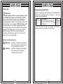
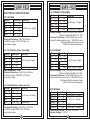
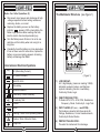
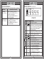
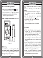
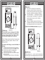
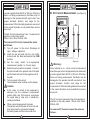
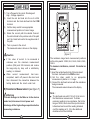
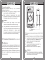
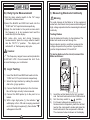
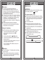
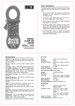
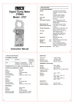
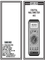
DIGITAL
MULTIMETER
405
TAKE MEASUREMENT CAREFULLY AND YOU’LL
SPARE YOUR METER AND YOURSELF, SOME PAIN
Nearly every electrical engineer has a hand held
digital multimeter (DMM). We sometimes take them
for granted, until we damage them or “burn them out”
if you incorrectly connect your DMM to a circuit, or if
you have the DMM on wrong setting, you damage the
meter and possibly hurt yourself. You can also get into
trouble if you try to measure the voltage across a
charged capacitor.
DMM users frequently burn their meters by trying
to measure current the same way as they measure
voltage, Remember, you measure voltage across a
circuit, and current through a circuit. When you use
the current input, your DMM becomes a lower
impedance circuit element. If you accidentally
connect this low impedance path across your circuit,
you’ll effectively short-circuit it. You can, therefore
send high current through your meter and severely
damage it. Unless the meter has a fused input, you
can even get an explosion or fire.
Even if you correctly insert your DMM into the
circuit, you can still damage your meter. Don’t try to
measure current in excess of your meter’s capacity.
Handheld DMMs usually have a maximum current
rating of 10A or 20A.
If you are measuring current in industrial
environment, you can easily exceed those ratings.
The best way to avoid damage is to use a clamp
meter or to connect a clamp attachment to your DMM.
To prevent excess current from flowing through
your meter, always disconnect the test leads from the
circuit under test whenever you change DMM
functions, Set your meter to the correct function, say
current and its highest range for the setting, say 10A.
Next, connect the test leads before you apply power
to the circuit. To be safe, start by setting your meter to
its highest range first.
Table of Contents
Title
Overview
Unpacking Inspection
Features
General Specification
Electrical Specification
DC Voltage
AC Voltage
AC Current
DC Current
Resistance
Frequency
Duty Cycle
Logic Test
Continuity & Diode Test
Page
1
2
3
4
5
Rules For Safe Operation
International Electrical Symbols
The Multimeter Structure
Functional Buttons
Display symbols
8
9
10
11
12
Measurement Operation
A. DC Voltage Measurement
B. AC Voltage Measurement
C. AC Current Measurement
D. DC Current Measurement
E. Measuring Resistance
F. Measuring Frequency
G. Duty Cycle Measurement
H. Logic Testing
I. Diode Test & Continuity
13
13
15
16
18
19
21
23
23
24
Maintenance
A. Replacing the Battery & fuse
Test Certificate
Warranty
26
26
27
29
Overview
Unpacking Inspection
! Warning
To avoid electric shock or personal injury, read
the “Safety Information” and “Rules for Safe
Operation”carefully before using the Meter.
Digital Multimeter Model - 405 (hereafter referred to
as “the Meter”) is a 4½ digits TRMS Multimeter with
steady operations, and highly reliable hand-held
measuring instrument having different measurement
positions. The Multimeter not only can measure
AC/DC Voltage, AC/DC Current, Resistance,
Frequency, Diode Test, Logic Test, but also has
Data Hold, Full Icon Display.
Open the package case and take out the Multimeter.
Check the following items carefully to see any
missing or damaged part :
Item
Description
Qty.
1
English Operating Manual
1 piece
2
Test Lead
1 pair
In the event you find any Part missing or damaged,
please contact your dealer immediately.
Terms in this manual
!
Warning : Identifies conditions and actions
that could result in serious injury
or even death to the user.
Caution : Identifies conditions and actions
that could cause damage or
malfunction instrument.
1
2
GENERAL SPECIFICATIONS :
FEATURES :
Low power consumption CMOS double
integration, A/D transform integrated circuit,
Auto Zero Calibration, Auto Polarity display,
Data Hold, Low Battery & Over range
indication.
n
Display : 4½ digit (19999 Counts) with digit
height 17mm and function/units sign
annunciators.
n
Selected Range displayed on LCD.
n
High Accuracy - Digital Reading.
n
Display
Digit Size
: 17mm(H)
Polarity
: Automatic, (-) negative
polarity indication.
Overrange
indication
: ‘1’ most significant digit.
Low Battery
Indication
: The “ - + ” sign is displayed
when the battery voltage
drops below the operating
Voltage.
Auto Power
Off
: Meter automatically shuts
down after approx.
45.minutes of inactivity.
Instant Continuity Buzzer.
n
Overload Protection in all Ranges.
n
Recessed Safety Designed Input Jacks.
n
“ DATA - HOLD ” switch freezes reading.
n
CE Approved, GS-approved.
n
IEC61010 overload category II
n
3
: 4½ digit LCD.
Maximum reading 19999
with Function and unit sign
annunciators.
Measurement rate : 2.5 times per Second, nominal
Operating
environment
: 0°C to + 50°C, <70% R.H.
Storage
temperature
: -20°C to 60°C, 0 to 80% RH
with battery removed.
Power
: Single 9 V Battery.
Power
Consumption
: 14mW Typical.
Dimension
: 189mm (H) X 87mm(W) X
37mm(D)
Weight
: Approx. (330 grams)
including battery.
Accessories
: Test Leads, Carrying Case,
User Manual, Battery,
Tilt stand, Protective Holster
4
ELECTRICAL SPECIFICATION :
DC VOLTAGE
AC CURRENT (TRUE RMS)
Range
Resolution Accuracy
200 m
A 10
nA
nA
2
mA 100
±(0.8% rdg + 10 dgts)
m
A
20 mA 1
m
A
200 mA 10
±(2.5% rdg + 10 dgts)
20
A* 1
mA
Range
Resolution Accuracy
10
m
V
200 mV
100
m
V
2
V
20
V
1
mV ±(0.05% rdg + 3dgts)
200
V
10
mV
1000 V
100
mV
Input Impedance : 10MW
Overload Protection : 500V DC/350Vrms
on 200mV range, 1000V DC/750V rms
on all other ranges
Burden Voltage : 300mV for 200m
A, 2mA, 20mA
600mV for 200mA & 800mV for 20A.
Overload Protection : 500mA/600V fuse on mA
inputs (fast blow ceramic fuse). * 20A/600V fuse on
20A inputs (fast blow ceramic fuse).
20A for 30 seconds maximum.
AC VOLTAGE 50Hz~500Hz (TRUE RMS)
DC CURRENT
Range
Resolution Accuracy
m
V
200 mV 10
V
2
V 100 m
±(1.0% rdg +10 dgts)
20
V 1
mV
mV
200 V 10
±(2.0% rdg + 20 dgts)
750 V 100 mV
Input Impedance : 10MW
Overload Protection : 500V DC or 350Vrms
on 200mV range, 1000V DC or 750Vrms
on all other range
Range
Resolution Accuracy
200 m
A
10
nA
100
nA
2
mA
±(0.5% rdg + 5 dgts)
1
m
A
20 mA
10
m
A
200 mA
20
A* 1
mA ±(2.0% rdg + 10 dgts)
Burden Voltage : 300mV for 200m
A, 2mA, 20mA
600mV for 200mA & 800mV for 20A.
Overload Protection : 500mA/600V fuse on mA
inputs (fast blow ceramic fuse). * 20A/600V fuse on
20A inputs (fast blow ceramic fuse).
20A for 30 seconds maximum.
AC VOLTAGE 500Hz to 2KHz (TRUE RMS)
Range
Resolution Accuracy
m
V
200 mV 10
V
2
V 100 m
±(2.0% rdg + 20 dgts)
20
V 1
mV
10
mV
200 V
Unspecifled
750 V 100 mV
Input Impedance : 10MW
Overload Protection : 500V DC or 350Vrms
on 200mV range 1000V DC or 750Vrms
on all other range
5
RESISTANCE
Range Resolution Accuracy
±(0.25% rdg + 10 dgts)
200 W
0.01
W
0.1
W
2 KW
±(0.15% rdg + 3 dgts)
20 KW
1
W
200KW
10
W
±(0.25% rdg + 10 dgts)
2 MW
100
W
±(1.0% rdg + 10 dgts)
20 MW
1
KW
Overload Protection : 500V DC or AC rms
Burden Voltage : 3.3V DC
6
FREQUENCY
Range
Rules For Safe Operation (1)
Resolution
Accuracy
Input Imped.
2 KHz 0.1 Hz
// 10pF
20 KHz 1
Hz ±(0.5% rdg+3dgts) 10MW
200KHz 10 Hz
Sensitivity : 50mV rms (Sine Wave), 400mV rms
at > 30% and < 70% duty cycle
Input Frequency : More than 10 Hz at pulse width > 2m
sec.
Overload Protection : 500V DC or AC rms
DUTY CYCLE
Range Resol. Pulse Width
Accuracy
sec. ±(2.0% rdg +10dgts)
0 - 90.0% 0.1% > 10m
Overload Protection : 500V DC or AC rms
Frequency Range : 20 Hz to 20 KHz
LOGIC TEST
Threshold
Pulse Rep Pulse Rise
Pulse
(max)
Logic Hi Logic Low Width(min) (max)
1Mpps
10m
sec
2.8V±0.8V 0.8V±0.5V
25ns
Test Voltage : 5V DC
Duty Cycle : >20% and <80%
Indication : 40msec beep at logic Hi
Overload Protection : 500V DC or AC rms
Frequency Response : 20MHz
CONTINUITY TEST
Range
2V
Open Circuit
Response
Audible
Volts
Time
Indication
Approx. 500ms 3.3V DC Typical
Less than 150W
Overload Protection : 500V DC or AC rms
DIODE TEST
Range Resol.
2V
Accuracy
0.1mV ±(0.5% rdg + 1dgt)
Test Open Circuit
Current
Volts
1.0mA
3.3V DC Typical
Overload Protection : 500V DC or AC rms
7
! Warning
To avoid possible electric shock or personal
injury, and to avoid possible damage to the
Meter or to the equipment under test, adhere to
the following rules :
Before using the Meter inspect the case. Do not
use the Meter if it is damaged or the case (or
part of the case) is removed. Look for cracks or
missing plastic. Pay attention to the insulation
around the connectors.
n
Inspect the test leads for damaged insulation or
exposed metal. Check the test leads for
Continuity. Replace damaged test leads with
identical electrical Specifications before using
the Meter.
n
Do not apply more than the rated voltage, as
marked on the Meter, between the terminals or
between any terminal and grounding.
n
The rotary switch should be placed in the right
position and no any changeover of range shall
be made while measurement is conducted to
prevent damage of the Meter.
n
When measurement is taken at an effective
voltage over 60V in DC or 30V rms in AC,
special care should be taken for there is danger
of electric shock.
n
Use the proper terminals, function, and range
for your measurements.
n
Do not use or store the Meter in an environment
of high temperature, humidity, explosive,
inflammable and strong magnetic field. The
performance of the Meter may deteriorate after
the meter is dampened.
n
When using the test leads, keep your fingers
behind the finger guards.
n
8
Rules For Safe Operation (2)
Disconnect circuit power and discharge all high
-voltage capacitors before testing resistance,
continuity, diodes, or current.
n
Replace the battery as soon as the battery
indicator - + appears. With a low battery, the
Meter might produce false readings that can
lead to electric shock and personal injury.
n
Turn the Meter power off when it is not in use
and take out the battery when not using for a
long time.
n
Constantly check the battery as it may leak when
it has not been used for some time, replace the
battery as soon as leaking appears. A leaking
battery will damage the Meter.
The Multimeter Structure (see figure 1)
n
LOGIC
V
1
TUV SAFETY APPROVED TO IEC1010
2
DATA
HOLD
POWER
AUTO POWER OFF
TRUE RMS
V
20
200
750
1000 200
V
20
2
2
200m
200m
LOGIC
200m
2
20m
20A
200m
A 2m
2m
A
20m
20A
200m
200m
200k
4
20M
20k
2k
DUTY%
Hz
20A
International Electrical Symbols
1.9999
DC
200 2k 20k
m
A mA
2M
200k
COM
W
CAT. II
VW
Hz
3
20A MAX
FUSED
200mA MAX
FUSED
1000V
750V
MAX
405 MULTIMETER
AC (Alternating Current).
~
DC (Direct Current).
Both DC & AC.
~
Grounding.
Double Insulated.
- +
Deficiency of Built-In Battery.
Continuity Test.
Diode.
Fuse.
!
Warning ! Refer to the Operating Manual.
Caution ! Risk of Electric Shock.
( Figure 1)
1) LCD DISPLAY :
A 4½ digit display (maximum reading 19999)
indicates measured values, and features
symbols indicating function, Low Battery,
Continuity, Diode, Logic.
2) FUNCTION SELECTOR :
To Select ACV, DCV, ACA, DCA, Resistance,
Frequency, Diode, Continuity & Logic Test.
3) INPUT JACKS (VW
,
mA
,
A
and COM) :
Test leads are inserted into these jacks for
Voltage, Resistance, Current measurements,
Continuity & Diode Checks.
4) PROTECTIVE HOLSTER :
Prevents the instrument from damage.
Logic test
9
10
Functional Buttons
Display Symbols
Below table indicates the functional button operations
Buttons
POWER
(Black Button)
DATA-HOLD
(Black Button)
~
Operation Performed
H
Switch the Meter on and off.
n
Press the POWER button to
switch on the Meter.
n
Press the POWER button to
turn off the Meter.
Press HOLD Button to hold the
reading on the display.
n
Press HOLD button again to
exit hold mode.
(see figure 2)
1.9.9.9.9
( Figure 2)
n
No. Symbol
Meaning
Dangerous Voltages.
1
The battery is low.
! Warning : To avoid false readings,
which could lead to possible electric
shock or personal injury, replace the
battery as soon as the battery
indicator appears.
Indicator for AC voltage or current, The
displayed value is the mean value.
2
- +
3
~
Indicates negative reading.
4
Test of diode.
5
6
H
Data Hold is active.
The continuity buzzer is on.
7
8
A
A : Amperes (amps). The unit of current.
9
V
V : Volts. The unit of voltage.
10
Hz
Hz : The unit of frequency.
%
% : The unit of Duty cycle.
11
12
W
: Ohm. The unit of resistance.
W
, kW
,
3
KW
: kilohm. 1 x 10 ohms.
MW
6
MW
: Mega Ohm 1 x 10 ohms.
13
: The symbol of logic Hi
: The symbol of logic Low
11
12
Measurement Operation
Make sure the Low Battery display - + is not
on, otherwise false readings may be provided.
n
Pay extra attention to the ! symbol which is
located besides the input terminals of the Meter
before carrying out measurement.
n
A) DC voltage measurement (see figure 3)
The DC Voltage ranges are :200mV, 2V, 20V, 200V,
1000V.
To measure DC voltage, connect the Meter as
follows :
1) Insert the red test lead into the VW
input terminal
and the black test lead into the COM input
terminal
2) Set the rotary switch to an appropriate
measurement position in V
range.
3) Connect the test leads across with the
object being measured.
LOGIC
1.9999
DC
V
~
The measured value is shown on the display.
TUV SAFETY APPROVED TO IEC1010
2
DATA
HOLD
POWER
Caution :
AUTO POWER OFF
TRUE RMS
V
20
750
200
1000 200
V...
20
2
2
200m
LOGIC
20m
20A
200m
2m
A
20m
20A
200m
200m
200k
20M
20k
2k
DUTY%
200 2k 20k
Hz
m
A mA
20A
!
20A MAX
FUSED
2M
200k
COM
!
200mA MAX
FUSED
W
CAT. II
If the value of voltage to be measured is
unknown, use the maximum measurement
position (1000V) and reduce the range step by
step until a satisfactory reading is obtained.
n
The LCD displays “1” indicating the existing
selected range is overloaded, it is required to
select a higher range in order to obtain a correct
reading.
n
In each range, the Meter has an input impedance
n
200m
200m
A 2m
VW
Hz
Black
Red
...MAX
1000V
750V
405 MULTIMETER
( Figure 3 )
! Warning
To avoid harms to you or damages to the Meter
from electric shock, please do not attempt to
measure voltages higher than 1000V or 750V rms
although readings may be obtained.
13
of approx. 10MW
. This loading effect can cause
measurement errors in high impedance circuits.
If the circuit impedance is less than or equal to
10kW
, the error is negligible (0.1% or less).
When DC voltage measurement has been
completed, disconnect the connection between
the testing leads and the circuit under test.
n
14
B) AC Voltage Measurement (see figure 4)
Caution :
If the value of voltage to be measured is
unknown, use the maximum measurement
position (750V) and reduce the range step by
step until a satisfactory reading is obtained.
n
The LCD displays “ 1 “ indicating the existing
selected range is overloaded, it is required to
select a higher range in order to obtain a
correct Reading.
n
When AC Voltage measurement has been
completed, disconnect the connection between
the testing leads and the circuit under test.
n
LOGIC
9.1999
V
DC
~
TUV SAFETY APPROVED TO IEC1010
2
DATA
HOLD
POWER
AUTO POWER OFF
TRUE RMS
V
20
200
750
1000 200
V...
20
2
2
200m
200m
LOGIC
200m
20m
20A
A 2m
200m
2m
A
20m
20A
200m
200m
200k
20M
20k
2k
DUTY%
Hz
200 2k 20k
m
A mA
20A
!
20A MAX
FUSED
2M
200k
COM
!
200mA MAX
FUSED
W
CAT. II
VW
Hz
Black
Red
...MAX
1000V
750V
405 MULTIMETER
!
Warning :
C) AC Current Measurement (see figure 5)
( figure 4)
LOGIC
1.9999
DC
To avoid harm to you or damages to the Meter
from electric shock, please do not attempt to
measure voltages higher than 1000V or 750V
rms although readings may be obtained.
V
2
DATA
HOLD
AUTO POWER OFF
TRUE RMS
V
20
200
750
1000 200
V...
20
2
2
200m
200m
LOGIC
200m
The AC Voltage measurement has 5 measurement
positions on the rotary switch : 200mV, 2V, 20V,
200V and 750V
20m
20A
200m
A 2m
2m
200k
20M
20k
2k
DUTY%
To measure AC Voltage, connect the Meter as
follows :
15
A
20m
20A
200m
200m
Hz
1) Insert the red test lead into the VW
terminal
and the black test lead into the COM terminal.
2) Set the rotary switch to an appropriate
measurement position in V ~ range.
3) Connect the test leads across with the object
being measured.
The measured value is shown on the display,
~
TUV SAFETY APPROVED TO IEC1010
POWER
200 2k 20k
m
A mA
20A
!
20A MAX
FUSED
2M
200k
COM
!
200mA MAX
FUSED
W
CAT. II
VW
Hz
Black
...MAX
1000V
750V
Red
405 MULTIMETER
!
(figure 5)
Warning :
Never attempt an in - circuit current measurement
where the open circuit voltage between terminals and
16
ground is greater than 60V DC or 30V rms. If the fuse
burns out during measurement, the Meter may be
damaged or the operator himself may be hurt. Use
proper terminals, function, and range for the
measurement. When the testing leads are connected
to the current terminals, do not parallel them across
any circuit.
D) DC Current Measurement
LOGIC
2)
3)
4)
5)
Caution
If the value of current to be measured is
unknown, use the maximum measurement
position (20A) and 20A terminal, and reduce
the range step by step until a satisfactory
reading is obtained.
n
When current measurement has been
Completed, switch off power in the circuit and
then disconnect the connection between
the testing leads and the circuit under test.
n
17
V
~
TUV SAFETY APPROVED TO IEC1010
2
DATA
HOLD
POWER
AUTO POWER OFF
TRUE RMS
V
20
200
750
1000 200
V...
20
2
2
200m
200m
LOGIC
200m
20m
20A
200m
A 2m
2m
A
20m
20A
200m
200m
200k
To measure AC Current, connect the meter
as follows :
Turn off power to the circuit. Discharge all
High - Voltage capacitors.
Insert the red test lead into the mA or 20A
terminal and the black test lead into the COM
terminal.
Set the rotary switch to an appropriate
measurement position in Current range.
Break the current path to be tested. Connect
the red test lead to the positive side of the path
and the black test lead to the negative side of
the path.
Turn on power to the circuit.
The measured value is shown on the display.
1.9999
DC
The AC Current measurement has 5 measurement
positions on the rotary switch:
200m
A, 2mA, 20mA, 200mA, 20A.
1)
(see figure 6)
20M
20k
2k
DUTY%
Hz
200 2k 20k
m
A mA
20A
!
20A MAX
FUSED
2M
200k
COM
!
200mA MAX
FUSED
W
CAT. II
VW
Hz
Black
...MAX
1000V
750V
Red
405 MULTIMETER
(figure 6)
!
Warning :
Never attempt an in - circuit current measurement
where the open circuit voltage between terminals and
ground is greater than 60V DC or 30V rms. If the fuse
burns out during measurement, the Meter may be
damaged or the operator himself may be hurt. Use
proper terminals, function, and range for the
measurement. When the testing leads are connected
to the current terminals, do not parallel them across
any circuit.
The DC current measurement has 5 measurement
positions on the rotary switch : 200m
A, 2mA, 20mA,
200mA, 20A.
To measure DC Current, connect the meter as
follows :
18
1) Turn off power to the circuit. Discharge all
High - Voltage capacitors.
2) Insert the red test lead into the mA or 20A
terminal and the black test lead into the COM
terminal
3) Set the rotary switch to an appropriate
measurement position in Current range.
4) Break the current path to be tested. Connect
the red test lead to the positive side of the path
and the black test lead to the negative side of
the path.
5) Turn on power to the circuit.
The measured value is shown on the display.
LOGIC
1.9999
DC
V
TUV SAFETY APPROVED TO IEC1010
2
DATA
HOLD
POWER
AUTO POWER OFF
TRUE RMS
V
20
200
750
1000 200
V...
20
2
2
200m
200m
LOGIC
200m
20m
20A
200m
A 2m
2m
A
20m
20A
200m
200m
200k
20M
20k
2k
DUTY%
Hz
200 2k 20k
m
A mA
20A
!
20A MAX
FUSED
2M
200k
W
COM
!
200mA MAX
FUSED
CAT. II
VW
Hz
Black
...MAX
1000V
750V
Red
405 MULTIMETER
(figure 7)
Caution
If the value of current to be measured is
unknown, use the maximum measurement
position (20A) and 20A terminal, and reduce
the range step by step until a satisfactory
reading is obtained.
n
When current measurement has been
completed, switch off power in the circuit and
then disconnect the connection between the
testing leads and the circuit under test.
n
E) Resistance Measurement (see figure 7)
! Warning
To avoid damages to the Meter or to the devices
under test, disconnect circuit power and
discharge all the high-voltage capacitors before
measuring resistance.
19
The resistance range has 6 measurement positions
on the rotary switch : 200W
,
2
K
W
,
2
0
K
W
,
2
0
0
K
W
,
2
M
W
,
2
0
M
W
.
To measure resistance, connect the meter as
follows
1) Insert the red test lead into the VW
terminal and
the black test lead into the COM terminal.
2) Set the rotary switch to an appropriate
measurement position in W
range.
3) Connect the test leads across with the resistance
being measured.
The measured value is shown on the display.
Note :
The test leads can add 0.1W
to 0.3W
of error to
the Resistance measurement. To obtain
precision readings in low-resistance, that is the
range of 200W
, short-circuit the input terminals
beforehand and record the reading obtained
(call this reading as X). (X) is the additional
resistance from the test lead.
n
20
Then use the equation :
Measured resistance value (Y) - (X) = precision
Reading of resistance.
n
When there is no input, for example in open
circuit condition, the Meter displays “ 1”
n
When resistance measurement has been
completed, disconnect the connection between
the testing leads and the circuit under test.
LOGIC
1.9999
DC
V
~
TUV SAFETY APPROVED TO IEC1010
2
DATA
HOLD
POWER
AUTO POWER OFF
TRUE RMS
V
20
200
750
1000 200
V...
20
2
2
200m
200m
LOGIC
200m
20m
20A
200m
A 2m
2m
200k
20M
20k
Caution :
2k
DUTY%
Hz
Never connect high voltage to the input
n
200 2k 20k
m
A mA
20A
sockets with the switch in Resistance range.
A
20m
20A
200m
200m
!
20A MAX
FUSED
2M
200k
COM
!
200mA MAX
FUSED
W
CAT. II
VW
Hz
Black
...MAX
1000V
750V
Red
405 MULTIMETER
Using Resistance measurement function in a
n
Live circuit will produce false results and may
damage the instrument. In many cases
(figure 8)
the suspect component must be disconnected
from the circuit to obtain an accurate reading.
F) Frequency Measurement (see figure 8)
!
Warning :
To avoid harm to you or damages to the Meter, do not
attempt to measure voltages higher than 60V in DC or
The frequency measurement range is 2kHz, 20kHz,
200kHz.
To measure frequency, connect the Meter as follows :
1)
Insert the red test lead into the VW
terminal and
the black test lead into the COM Terminal.
2) Set the rotary switch in the appropriate
frequency range.
3) Connect the test leads across which the
frequency is to be measured.
The measured value is shown on the display.
30V rms in AC although reading may be obtained.
When the frequency signal to be tested is higher than
30V rms, the Meter cannot guarantee accuracy of
the measurement.
21
Caution :
When Hz measurement has been completed,
disconnect the connection between the testing
leads and the circuit under test.
n
22
G) Duty Cycle Measurement
1)Set the rotary selector switch to the "Hz" range
desired for a measurement.
2)Insert the BLACK and RED test leads into the
“COM” and “VW
” input terminals respectively.
3)Apply the test leads to the points across which
the frequency is to be measured and read the
result directly from the display.
4)To make duty cycle test during frequency
measurements, place the range selector switch
into the “DUTY %” position. The display will
indicate 0% of the frequency duty cycle.
Caution :
! The frequency ranges have overload protection
I) Measuring Diodes & Continuity
! Warning
To avoid damage to the Meter or to the equipment
under test, disconnect circuit power and discharge all
high-voltage capacitors before measuring diodes and
continuity.
Testing Diodes
Use the diode test function to check diodes, The
diode test sends a current through the
Semiconductor junction, and then measures the
voltage drop across the junction. A good silicon
junction drops between 0.5V and 0.8V.
To test a diode out of a circuit, connect the
Meter as follows :
to 500 VAC / VDC. Do not exceed this limit. To do
so could damage your multimeter.
LOGIC
1.9999
DC
V
TUV SAFETY APPROVED TO IEC1010
2
DATA
HOLD
POWER
H) Logic Testing
AUTO POWER OFF
TRUE RMS
V
20
200
750
1000 200
V...
20
2
2
200m
1
2.
3)
4)
5)
Insert the BLACK and RED test leads into the
“COM” and “VW
” input terminals respectively.
Select the logic function by rotating the selector
dial to the () logic position.
Connect the BLACK probe tip to the Common
Bus of the logic circuitry to be measured.
Connect the RED probe tip to the point to be
tested.
With a logic high pulse (1), the indicator "
"
will display in the L CD and a beeping sound will
emit. With a logic low pulse (O), the indicator " "
will appear in the LCD.
23
200m
LOGIC
200m
20m
20A
200m
A 2m
2m
A
20m
20A
200m
200m
200k
20M
20k
2k
DUTY%
Hz
200 2k 20k
m
A mA
20A
!
20A MAX
FUSED
2M
200k
COM
!
200mA MAX
FUSED
W
CAT. II
VW
Hz
...MAX
1000V
750V
Black
Red
405 MULTIMETER
1)
2)
3)
Insert the red test lead into the VW
terminal
and the black test lead into the COM terminal.
Set the rotary switch to
position.
For forward voltage drop reading on any
Semiconductor component, place the red test
lead on the component’s anode and place the
black test lead on the component’s cathode.
The measured value is shown on the display.
24
Maintenance
Caution :
In a circuit, a good diode will produce a
forward voltage drop reading of 0.5V to 0.8V;
However ; the reverse voltage drop reading can
Vary depending on the resistance of other path
ways between the probe tips.
n
Connect the test leads to the proper terminals
as said above, to avoid error display. The LCD
will display “1” indicating open-circuit for wrong
connection. The unit of diode is Volt (V),
displaying the positive connection voltage-drop
Value.
n
When diode testing has been completed,
disconnect the connection between the testing
leads and the circuit under test.
n
Testing for Continuity
To test for continuity, connect the Meter as below :
1. Insert the red test lead into VW
terminal
and the black test lead into the COM
terminal.
2. Set the rotary switch to
position
3. Connect the test leads across with the object
being measured.
The buzzer sounds if the resistance of a circuit
under test is less than 150W
.
The LCD displays the resistance value of a
circuit under test.
!
Warning
To avoid false reading, replace the battery as soon
as the battery indicator - + appears.
To replace battery / fuse :
Disconnect the connection between the testing
leads and the circuit under test, and remove the
testing leads away from the input terminals of
the Meter.
n
Turn the Meter OFF.
n
Remove the screws from the bottom case
and separate the bottom case from the top case.
n
Remove the battery/fuse from the battery/fuse
compartment.
n
Replace the battery/fuse with a new Standard
9V Battery/same specification fuse.
n
Rejoin the bottom case and the top case,
and install the screw.
n
- +
Caution :
The LCD displays “1” indicating the circuit being
tested is open.
n
When continuity testing has been completed,
disconnect the connection between the testing
leads and the circuit under test.
n
25
26
MUMBAI
TEST CERTIFICATE
DIGITAL MULTIMETER
This Test Certificate warrantees that
the product has been inspected and
tested in accordance with the published
specifications.
The instrument has been calibrated by
using equipment which has already
been calibrated to standards traceable
to national standards.
405
MODEL NO. ___________
SERIAL NO. ___________
DATE: ___________
QC
ISO 9001
REGISTERED
KUSAM-MECO
PASS
27
28
WARRANTY
Each “KUSAM-MECO” product is warranted to be
free from defects in material and workmanship
under normal use & service. The warranty period is
one year (12 months) and begins from the date of
despatch of goods. In case any defect occurs in
functioning of the instrument, under proper use,
within the warranty period, the same will be rectified
by us free of charges, provided the to and fro freight
charges are borne by you.
This warranty extends only to the original buyer or
end-user customer of a “KUSAM-MECO” authorized
dealer.
THIS WARRANTY IS BUYER’S SOLE AND
EXCLUSIVE REMEDY AND IS IN LIEU OF ALL
OTHER WARRANTIES, EXPRESS OR IMPLIED,
INCLUDING BUT NOT LIMITED TO ANY IMPLIED
WARRANTY OF MERCHANTABILITY OR
FITNESS FOR A PARTICULAR PURPOSE.
“KUSAM-MECO” SHALL NOT BE LIABLE FOR
ANY SPECIAL, INDIRECT, INCIDENTAL OR
CONSEQUENTIAL DAMAGES OR LOSSES,
INCLUDING LOSS OF DATA, ARISING FROM
ANY CAUSE WHATSOEVER.
All transaction are subject to Mumbai Jurisdiction.
This warranty does not apply for damaged Ic’s,
fuses, burnt PCB's, disposable batteries, carrying
case, test leads, or to any product which in “KUSAMMECO’s” opinion, has been misused, altered,
neglected, contaminated or damaged by accident or
abnormal conditions of operation or handling.
“KUSAM-MECO” authorized dealer shall extend this
warranty on new and unused products to end-user
customers only but have no authority to extend a
greater or different warranty on behalf of “KUSAMMECO”.
“KUSAM-MECO’s” warranty obligation is limited, at
option, free of charge repair, or replacement of a
defective product which is returned to a “KUSAMMECO” authorized service center within the
warranty period.
29
G 17,Bharat Industrial Estate, T. J. Road,
Sewree (W), Mumbai - 400 015. INDIA.
Sales Direct : (022) 24156638
Tel. : (022) 24124540, 24181649.
Fax : (022) 24149659
Email : [email protected]
Website : www.kusamelectrical.com
www.kusam-meco.co.in
30