1
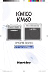
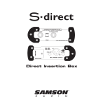
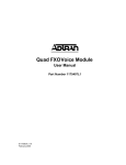
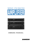
���
����
��
���
��
���
�
�����
��
���
���
���
���
����
���
��
���
���
����
����
���
����
���
����
��
�����
���
����
������������������
�����
��
�������
��������
��������
�������
���
�����
������������������������������
������������������������������������
Stereo Two-way Electronic Crossover
sxover_ownman.indd 1
S Class Signal Processors
�
�
6/8/04 9:21:36 PM
Table Of Contents
Introduction and Features
Front and Rear Panel Layout
Operating the S xover
Setting Up the S xover
Mono Sub Set-up
Wiring Guide
Specifications
3
4
5-6
7
8
8
Copyright 2004, Samson Technologies Corp.
Printed June 2004
Samson Technologies Corp.
575 Underhill Blvd.
P.O. Box 9031
Syosset, NY 11791-9031
Phone: 1-800-3-SAMSON (1-800-372-6766)
Fax: 516-364-3888
www.samsontech.com
sxover_ownman.indd 2
6/8/04 9:21:38 PM
S xover Introduction and Features
Introduction
Congratulations on your purchase of the S xover by Samson Audio! The S xover is a full
featured, stereo, two-way electronic crossover perfect for a variety of bi-amp speaker
applications in studio monitoring, live sound and fixed installations. With individual controls
for Input Level, as well as High and Low Frequency outputs, the S xover is small, but not
short on features. For expanded control, the S xover provides a Range switch allowing
you to adjust crossover frequency by ten times so you can configure a speaker system
with drivers from subs to tweets. The S xover, with its Mono Low switch, is a perfect
complement if youʼre adding a subwoofer to a studio monitor or PA system when using a
common subwoofer with stereo satellite speakers. Whatever your exact situation, the S
xover will provide high quality and reliable performance thanks to its solid build construction based around the extruded aluminum chassis and oversized rubber bumper feet.
In this manual, youʼll find a more detailed description of the features of the S xover, as
well as a guided tour through the front and rear panels, step-by-step instructions for using
the S xover, and full specifications. Youʼll also find a warranty card enclosed—please donʼt
forget to fill it out and mail it so that you can receive online technical support and so we
can send you updated information about other Samson products in the future.
S xover Features
•
Two-way Stereo Electronic Crossover
•
Adjustable Crossover frequency control.
•
High and Low Level Outputs.
•
Input Level Control.
•
Range control covering frequencies from subs to tweeters.
•
Mono Low switch for operating sub satellite system woofers.
•
Large rubber bumper feet.
•
Three year extended warranty.
3
sxover_ownman.indd 3
6/8/04 9:21:39 PM
S xover Front and Rear Panel Layout
Front Panel Layout
�
�
�
�
�
�
�
�
���
����
��
���
���
����
��
���
�
�����
��
���
���
���
���
����
���
����
���
����
��
���
���
����
��
�����
���
����
1
LEVEL- Used to adjust the input gain
from –00 to +0dB.
2
LOW - Adjusts the output gain of the Low
frequency bands from -12 to +12dB.
3
HIGH - Adjusts the output gain of the
High frequency bands from -12 to +12dB.
4
FREQUENCY CONTROL- This control
that sets the crossover point dividing
the frequency bands.
5
RANGE SWITCH - Selects the range at
which the frequency control operates,
either normal or times 10.
MONO LOW - Selects mono operation
for the low output.
6
Rear Panel Layout
�
�
�
�
�
������������������
�����
��
�������
��������
��������
�������
���
�����
������������������������������
������������������������������������
A
IN LEFT - 1/4-inch line level input for
the Left channel.
C
HIGH OUT - TRS connector with Left and
Right High frequency line outputs.
B
IN RIGHT - 1/4-inch line level input for
the Right channel.
D
LOW OUTPUT - TRS connector with Left
and Right Low frequency line outputs.
E
POWER IN DC INLET - Connect the supplied power adapter here.
4
sxover_ownman.indd 4
6/8/04 9:21:40 PM
Operating the S xover
Setting Up the S xover
The basic procedure for setting up and using your S xover is simple and takes only a few
minutes. Remove all packing materials (save them in case of need for future service).
There are many different ways to use the S xover, however the basic connection is the
same in most installations and applications. The following example details a typical 2-way
stereo sound system for using a bi-amp power arrangement. Follow the steps below to
connect your bi-amp system.
�
�
���
�����
��
���
������������
���
����
��
���
�
�����
��
���
���
���
���
����
���
��
���
����
���
����
��
���
��
�����
���
����
������
�����
������������������
�����
��
�������
��������
��������
�������
�������������
���
�����
�������������
������
���������
Servo 550 Power Amp (High)
��������������������������
CAUTION
RISK OF ELECTRIC SHOCK
DO NOT OPEN
�����
����������
������
FUSE
FUSE RATING
������������������������������������������������
!
SERIAL
NUMBER
BRIDGED
MONO
STEREO
12A/250V (115V)
6A/250V (230V)
USE CLASS 2 WIRING MAXIMUM LOAD IMPEDANCE 4�
LEFT
CAUTION
HEATSINK MAY BE
HOT! DO NOT BLOCK
AIRFLOW OR OVERHEATING MAY OCCUR
TO PREVENT SHOCK DO
NOT OPEN. NO USER
S E R V I C A B L E PA R T S
INSIDE. REFER SERVICING
TO QUALIFIED SERVICE
PERSONNEL. TO PREVENT
FIRE OR SHOCK HAZARD
DO NOT EXPOSE TO RAIN
OR MOISTURE.
+RIGHT
GROUND
RIGHT
LEFT+
INPUTS
(BALANCED
10K�/0dBm0)
OUTPUT 250W/4�
TIP RING SLEEVE
RIGHT
LEFT
TIP
+
RING
SLEEVE GND
~AC INPUT
115V/230W, 50/60HZ
510W (115V)900W (230V)
��������
S1500 Power Amp (Mid)
����������
OUTPUT
INPUT
PUSH TO RESET
20A/250V
(4�~8�)
(4�~8�)
(4�~8�)
(4�~8�)
CH 2
CH 1
BALANCED
0dBm
TIP=HOT
TRS
RING=COLD
BALANCED SLEEVE=GND
~AC INPUT
115V 60Hz, 920W
BALANCED
0dBm
XLR
BALANCED
CH 2
BRIDGED
3=COLD
2=HOT
1=GND
CH 1
PARALLEL
STEREO
•
���������
Connect the AC/DC power adapter to the DC inlet, but donʼt plug the AC/DC power
adapter in just yet.
5
sxover_ownman.indd 5
6/8/04 9:21:42 PM
Operating the S xover
Setting Up the S xover
•
Set the LEVEL, LOW and HIGH Output controls all the way down by turning them fully counter
clockwise.
•
Using two standard 1/4-inch phone cables, connect the your mixerʼs left and right output to the S
xoverʼs LEFT and RIGHT INPUT.
•
Use a “Y” cable with a 1/4-inch TRS (TIP RING SLEEVE) to two 1/4-inch TS (TIP SLEEVE) to
connect the Left and Right LOW Output to the power amp connected to the low frequency drivers. For a detailed wiring diagram for the 1/4-inch TRS "Y" cable see page 8 in this manual.
•
Use a second “Y” cable with a 1/4-inch TRS (TIP RING SLEEVE) to two 1/4-inch TS (TIP
SLEEVE) to connect the Left and Right HIGH Output to the power amp connected to the high
frequency drivers.
•
At this point connect the power amplifiers to the low and high frequency speakers following the
manufacturers recommended procedures outlined in their individual owner manuals.
•
Set the position of the RANGE switch so that the FREQ control is operating in the desired frequency range. The Range control operates from 35 Hz to 800 Hz when the RANGE switch is out,
but with the RANGE switch in the frequency is multiplied by 10 times so the range becomes 350
Hz to 8 kHz.
•
Once the RANGE switch is properly set, use the FREQ control to set the crossover point between
the low and high frequency driver. Be sure to check with the speaker manufacturerʼs recommended operating range for the individual drivers to avoid any serious damage that may result.
•
Now, plug in the AC/DC adapter while appling the “Golden Rule of Audio” to power up your system.
IMPORTANT NOTE: The “Golden Rule of Audio” - LAST ON / FIRST OFF
When running a loudspeaker system with one or multiple power amplifiers, it is highly recommended that you
follow the LAST ON / FIRST OFF rule. When powering up your sound system, turn your power amplifier on last.
When you power down your system, turn your power amplifiers off first. This will prevent any switching spikes
you may get from other gear in your system, and help prevent unnecessary pops that can sometimes cause
speaker damage.
•
Run a signal from your mixer( like from a CD or MP3 player) and adjust the output level so a
good signal is sent to the S xover. Now adjust the LEVEL control to about half way up.
•
Finally, set the LOW and HIGH controls to about half-way and adjust the levels with an RTA
(REAL TIME ANALYZER), like a Samson D1500, or use your ears to dial in the blend between
the low and high drivers.
6
sxover_ownman.indd 6
6/8/04 9:21:44 PM
S xover Sub System Set-up
Typical Set-up for Satellite systems with Mono Sub
The diagram below shows a typical set-up for using the S xover with a sub woofer for PA application
using full range speakers in stereo along with a common sub running in mono. You can use the same
type of hook-up for connecting a sub woofer to full range studio monitors in recording set-ups. Set the
RANGE switch out and the Mono switch in and follow the diagram below to connect your system.
7
sxover_ownman.indd 7
6/8/04 9:21:48 PM
S xover Specifications
1/4-inch TRS (TIP RING SLEEVE) to two 1/4-inch TS (TIP SLEEVE) INSERT Y CABLE Wiring Diagr
Frequency Response
10Hz to 160kHz, -1dB
Dynamic Range
Noise Level
>95dB
-80dBu
THD
.003% typical, 1% at +15dBu out
Maximum Ouput Level
Max Input Level
Input Impedance
Output Impedance
+15 dBu
+22 dBu
10k Ohm
100 Ohm
Dimensions
5.65” L x 4.13” W x 2” H (144mm L x 105mm
W x 51mm H)
16.5 oz., 419 gm.
Weight
Samson Technologies Corp.
575 Underhill Blvd.
P.O. Box 9031
Syosset, NY 11791-9031
Phone: 1-800-3-SAMSON (1-800-372-6766)
Fax: 516-364-3888
www.samsontech.com
sxover_ownman.indd 8
6/8/04 9:21:58 PM