1
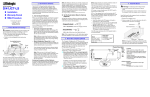
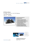
MP 34E User Manual M-037/M-038 Release: 3.7.1 Worm-Gear Rotation Stages T Date: 2007-08-24 This document describes the following product(s): T M-037.00 T 60 mm, manual drive T M-037.DG T 60 mm, DC motor gearhead M-037.PD 60 mm, PWM DC motor direct drive M-037.2S 60 mm, 2-phase stepper motor drive, open-loop M-038.001 100 mm, manual drive M-038.DG1, M-038.VG1 100 mm, DC motor gearhead M-038.VG1, M-038.VP1 100 mm, 10-6 hPa vacuum versions M-038.PD1, M-038.VP1 100 mm, PWM DC motor direct drive M-038.2S1 100 mm, 2-phase stepper motor drive, open-loop T T T T T T T T T T T P T T P T © Physik Instrumente (PI) GmbH & Co. KG Auf der Römerstr. 1 ⋅ 76228 Karlsruhe, Germany Tel. +49-721-4846-0 ⋅ Fax: +49-721-4846-299 [email protected] ⋅ www.pi.ws C Declaration of Conformity according to ISO / IEC Guide 22 and EN 45014 Manufacturer: Manufacturer´s Address: Physik Instrumente (PI) GmbH & Co. KG Auf der Römerstrasse 1 D-76228 Karlsruhe, Germany The manufacturer hereby declares that the products Worm-Gear Rotation Stages Product Name: Model Numbers: M-037/M-038 Product Options: all complies with the following European directives: 73/23/EEC, Low voltage directive 89/336/EEC, EMC-Directive 98/37/EC, Machinery Directive The applied standards certifying the conformity are listed below. Electromagnetic Emission: EN 61000-6-3, EN 55011 Electromagnetic Immunity: EN 61000-6-1 U U U U Safety (Low Voltage Directive): EN 61010-1 Safety of Machinery: EN 12100 U U U U July 09, 2007 Karlsruhe, Germany Dr. Karl Spanner President Physik Instrumente (PI) GmbH & Co. KG is the owner of the following company names and trademarks: ® PI , ActiveDrive™ P P Copyright 1999–2007 by Physik Instrumente (PI) GmbH & Co. KG, Karlsruhe, Germany. The text, photographs and drawings in this manual enjoy copyright protection. With regard thereto, Physik Instrumente (PI) GmbH & Co. KG reserves all rights. Use of said text, photographs and drawings is permitted only in part and only upon citation of the source First printing 2007-08-24 Document Number MP 34E, Release 3.7.1 M-037_User_MP34E371.doc X X X X X X This manual has been provided for information only and product specifications are subject to change without notice. About This Document T Users of This Manual This manual is designed to help the reader install and operate the M-037/M-038 Worm-Gear Rotation Stages. It assumes that the reader has a fundamental understanding of basic servo systems, as well as motion control concepts and applicable safety procedures. The manual describes the physical specifications and dimensions of the M-037/M-038 WormGear Rotation Stages as well as the installation procedures which are required to put the associated motion system into operation. This document is available as PDF file. Updated releases are available for download from www.pi.ws, or by email: contact your Physik Instrumente Sales Engineer or write [email protected] X X X X X X X X HTU UTH HTU UTH Conventions The notes and symbols used in this manual have the following meanings: WARNING Calls attention to a procedure, practice or condition which, if not correctly performed or adhered to, could result in injury or death. CAUTION Calls attention to a procedure, practice, or condition which, if not correctly performed or adhered to, could result in damage to equipment. NOTE Provides additional information or application hints. Related Documents The motion controller and the software tools which might be delivered with M-037/M-038 WormGear Rotation Stages are described in their own manuals. Updated releases are available for download from www.pi.ws or email: contact your Physik Instrumente Sales Engineer or write [email protected]. X X HTU HTU UTH UTH X X ! Contents 1 TU Introduction UT TU 1.1 1.2 1.3 UT TU TU UT TU TU UT UT UT TU UT Model Survey 5 Operation 7 UT TU UT 3 TU Description .................................................................................2 Safety Precautions .....................................................................3 Prescribed Use ...........................................................................4 TU 2 TU UT TU UT 3.1 3.2 3.3 UT TU TU UT TU TU UT DC Motor Versions .....................................................................7 Stepper Motor Versions..............................................................9 Motion Control Parameters ......................................................10 TU UT UT TU UT 3.3.1 3.3.2 4 TU UT TU TU UT TU www.pi.ws UT 11 UT UT TU TU UT TU Cable Connectors and Pin Assignments ..................................13 Dimensions ..............................................................................16 TU UT UT 4.2.1 4.2.2 UT UT TU 4.1 4.2 5 DC Motor Versions ................................................................... 10 Stepper Motor Versions ........................................................... 10 TU Technical Data UT TU 2 UT M-037 Models........................................................................... 16 M-038 Models........................................................................... 19 TU UT TU UT TU UT TU UT Old Equipment Disposal TU 21 UT M-037/M-038 MP 34E Release 3.7.1 Page 1 Introduction 1 Introduction 1.1 Description Ultra-High Resolution Compact Design Unlimited Rotation Range Preloaded Worm Drive for Zero Backlash ActiveDrive™ DC Motor, Stepper Motor and Manual Versions Compatible with National Instruments Motion Controllers Clear Aperture of 20 mm or 40.2 mm Ø Limit and Reference (Origin) Switches Worm Gear Drive All M-037 and M-038 rotation stages are equipped with wormgear drives allowing unlimited rotation in either direction. An integrated spring pre-load eliminates backlash. The worm gear ratios are 180:1 (M-037s) and 176:1 (M-038s), corresponding to turntable rotations of 2.000° and 2.045°, respectively, per revolution of the drive shaft. Three Motor-Drive Options The M-037.DG and M-038.DG1 models are equipped with a DC motor and shaft-mounted encoder, and have a min. incremental motion of 3.5 µrad The M-037.2S and M-038.2S1 models feature a direct-drive, 2phase stepper motor, providing very smooth operation and a resolution of 5.5 µrad per step. The M-037.PD and M-038.PD1 models feature the highperformance ActiveDrive™ system. The ActiveDrive™ design, developed by PI, features a high-efficiency PWM (pulse width modulation) servo-amplifier mounted side-by-side with the DC motor and offers several advantages: www.pi.ws Increased efficiency, by eliminating power losses between the amplifier and motor M-037/M-038 MP 34E Release 3.7.1 Page 2 Introduction Reduced cost of ownership and improved reliability, because no external driver is required Elimination of PWM amplifier noise radiation, by mounting the amplifier and motor together in a single, electrically shielded case Limit and Reference Switches For the protection of your equipment non-contact Hall-effect limit and reference (origin) switches are integrated in the motorized versions. The direction-sensing reference switch supports advanced, high-precision automation applications. 1.2 Safety Precautions The following safety precautions should be observed when operating M-03x series rotation stages: WARNING The stages are motorized by powerful electric motors and can accelerate to high speeds and can generate high forces. If handled improperly, the stages may cause injuries. ! CAUTION When the stage is connected to the motor controller (and/or amplifier) be aware that the stage could start an undesired move for reasons that may not be immediately apparent. Be aware that failure of the motor controller may drive the stage into a hard stop at high speed. ! www.pi.ws CAUTION Connecting a DC motor to a stepper motor controller or vice versa may cause damage to the motor. M-037/M-038 MP 34E Release 3.7.1 Page 3 Introduction 1.3 Prescribed Use M-037 and M-038 stages must not be used for applications not in conformance with this manual. Observe all safety precautions given in this User Manual. Standard M-037 and M-038 stages are designed to operate under normal ambient conditions at least as listed here. More stringent conditions given in the Technical Data table (p. 11) are, of course, also met. X www.pi.ws X Indoor use Altitude up to 2000 m Temperature range 5°C to 40°C Max. relative humidity 80% for temperatures up to 31°C, decreasing linearly to 50% relative humidity at 40°C Degree of pollution: 2 M-037/M-038 MP 34E Release 3.7.1 Page 4 Model Survey 2 Model Survey M-037 and M-038 stages differ in platform and aperture diameter (and related specifications, such as weight) and the slightly different worm-gear ratio. The table below summarizes the models available: Drive Type Model Number 100 mm 60 mm Platform w. Platform w. 40.2 mm 20 mm Aperture Aperture M-037.00 M-037.DG M-038.001 * M-038.DG1* TPF FPT M-038.VG1 M-038.VP1 M-037.PD M-038.PlD1 M-037.2S M-038.2S1* Manual thumbscrew Closed-loop DC motor / gearhead M-038.DG1 vacuum-compatible to 10-6 hPa M-038.PD1 vacuum-compatible to 10-6 hPa Closed-loop DC motor direct drive with integrated PWM amplifier (ActiveDrive™ DC motor) 2-phase stepper motor (openloop) TP TP TP TP The DC motor/gearhead versions feature 3-watt DC motors with 29.6:1 backlash-free gearheads and 2000 counts/revolution encoders mounted on the motor shaft. The stepper motor versions are equipped with 2-phase stepper motors providing 20 000 micro-steps / revolution. Coarse position can be read from an adjustable scale ring on the outer edge of the turntable, graduated in 2° increments or, on the M-037 and all manual models, from a drive-shaftmounted indicator with 0.1 degree graduations. C * TP www.pi.ws PT The older M-038.00, M-038.DG and M-038.2S are no longer available M-037/M-038 MP 34E Release 3.7.1 Page 5 Model Survey M-037.00 T T T T M-038.PD1 T M-037.DG T T T Fig. 1: Sampling of M-037 and M-038 stages www.pi.ws M-037/M-038 MP 34E Release 3.7.1 Page 6 Operation 3 Operation Manual versions are operated by turning the thumbscrew. Each full turn corresponds to 2° (2.045° for M-038.001) of platform motion. The motor-driven versions require a compatible motor controller. CAUTION ! 3.1 Connecting a DC motor to a stepper motor controller or vice versa may cause damage to the motor. DC Motor Versions The DC motor versions come in analog and PWM models. The PWM versions (M-037.PD, M-038.PD1) feature much higher power. The motor direction is determined by a TTL logic signal on the PWM-sign line, the speed by a PWM-coded TTL-level signal on the PWM-magnitude line. Only low currents flow in these lines because the motor power is drawn from a separate, 24 VDC supply. In the DC-motor versions, the motor speed is determined by the voltage (max. 12 V differential) on the motor power lines and the direction by the polarity. If the "Motor +" line is more positive than the "Motor -" line, then the motor moves in the positive direction. The motor power thus comes from the controller. PI offers DC motor controllers with a wide range of size and performance. In general the DC motor versions can be controlled by the C-843, C-848, C-880 and C-862 Mercury™ controllers illustrated below. www.pi.ws M-037/M-038 MP 34E Release 3.7.1 Page 7 Operation Fig. 2: DC-motor controllers: C-848 and C-880 benchtop/ rackmount (background, top to bottom), C-843 PCI bus cards and Mercury controllers, alone and networked (foreground) DC Motor C-880 Controllers: up to 18 ** Axes per controller * RS-232, Host PC RS-422 or interface IEEE (GPIB) yes, Multiple separate controllers ports on same PC TPF TPF FPT C-848 2 or 4 C-843 PCI Card 2 or 4 C-862 Mercury™ 1 Internal (PCI bus) RS-232 daisy chain bus yes, same port; also with C-663 FPT RS-232, RS-422 or IEEE (GPIB) yes, separate ports yes, separate slots Current models of all of PI's DC motor controllers can handle both PWM and analog motors in any combination. The C-862 Mercury™ is internetworkable with other Mercury™ controllers, including the C-663 Mercury™ Step. * Multi-axis controllers can drive a mix of PWM and analog motors Custom configurations with networked controllers operating off a single host PC port (RS-422, RS-422, GPIB, IEEE 488, USB, TCP/IP) and controlling hundreds of axes are possible. TP PT ** TP www.pi.ws PT M-037/M-038 MP 34E Release 3.7.1 Page 8 Operation 3.2 Stepper Motor Versions ! CAUTION Commanding a velocity above the maximum possible for the stage will cause the motor to stall. Because stepper motors do not have position encoders, the position counter will continue to increment. The controller's motor position may not correspond with the actual motor position and this might endanger your application. The maximum velocity depends on various influences like operating voltage, phase current setting and mechanical load. Datasheet values are for orientation only and may not work in all applications. M-037.2S and M-038.2S1 stages are equipped with 2-phase stepper motors. In conjunction with the C-663 stepper motor controller, high-resolution microstepping achieves an angular resolution of 1.1 arc seconds. Note that stepper-motor versions do not have encoders and are designed for open-loop operation. See the controller User Manual for details on operating and networking stepper motor axes. Fig. 3: Mercury™ Step stepper motor controller Stepper Motor Controller: C-663 Mercury™ Step 1 Axes per controller USB and/or RS-232 daisy chain Host PC interface bus Multiple controllers on same PC yes, same port, also with C-862 Internetworking of C-663 Mercury™ Step stepper motor controllers with each other and with C-862 Mercury™ DC motor controllers is supported, for control of up to 16 axes off a single RS-232 * or USB port. TPF FPT * The RS-232 output stages of some PCs may not be capable of driving more than 6 units; if this is a problem use USB to interface the first C-663 with the PC. TP www.pi.ws PT M-037/M-038 MP 34E Release 3.7.1 Page 9 Operation 3.3 Motion Control Parameters 3.3.1 DC Motor Versions The following tables give recommended starting values for the servo-control parameters for M-037 and M-038 stages and the different PI DC motor controllers. See the controller User Manual for details. Using C-843, C-848 and C-880 Motor Controllers 1 with: Stage M-037.DG/M-038.DG1 with Gear M-037.PD/M-038.PD1 with Drives PWM amplifier Parameter Recommend Operating Range RecomOperating ed Value mended Range Value DP250 DP50 – DP300 DP200 DP150 – DP250 p –term (DP) DI40 DI0 – DI50 DI10 DI0 – DI50 i –term (DI) DD800 DD0 – DD1200 DD300 DD0 – DD500 d –term (DD) DL2000 DL0 – DL2000 DL2000 DL0 – DL2000 L – limit (DL) SV120000 SV1 – SV190000 SV120000 SV1 – SV240000 Velocity (SV) SA20 – SA1200 SA450 SA10 – SA600 Acceleration (SA) SA800 TPF FPT Using C-862 Mercury Controllers with M-037.DG/M-038.DG1 with M-037.PD/M-038.PD1 with PWM Gear Drives amplifier Parameter Recommen Operating RecomOperating ded Value Range mended Value Range DP250 50 – DP300 DP250 50 – DP250 p –term (DP) DI40 0 – 50 DI40 0 – 50 i –term (DI) DD800 0 – 1200 DD800 0 – 1200 d –term (DD) DL2000 0 – 2000 DL2000 0 – 2000 L – limit (DL) SV120000 1 – 190000 SV120000 1 – 220000 Velocity (SV) 1000 – 2200000 SA1500000 1000 – 3000000 Acceleration (SA) SA800000 Stage For the stepper motor versions, the maximum velocity is the most important operating parameter. depends on various influences like operating voltage, phase current setting and mechanical load. Datasheet values are for orientation only and may not work in all applications. 3.3.2 Stepper Motor Versions The most important operating parameter for the stepper motor versions is the maximum velocity. Exceeding it will cause stalling, and the position counter will be incorrect. Determine the maximum velocity empirically for your individual application and make sure that it is not exceeded in normal operation. Use the datasheet value of 10°/s as a starting point. TP 1 PT see User Manual of respective controller for detailed command survey www.pi.ws M-037/M-038 MP 34E Release 3.7.1 Technical Data 4 Technical Data M-037.00 M-037.DG M-037.PD M-037.2S* M-038.001 M-038.DG1 M-038.PD1 M-038.2S1* Units >360 >360 >360 >360 >360 >360 >360 >360 ° Rotary encoder Rotary encoder Rotary encoder Rotary encoder 2000 4000 2000 4000 Tolerance Motion and positioning Rotation range Integrated encoder Encoder resolution * TPF FPT -6 -6 cts./rev. Design resolution* 0.59 (34 x 10 ) 8.75 (0.0005) 5.45 (0.00031) 0.60 (35 x 10 ) 8.95 (0.0005) 5.58 (0.00032) µrad (deg) typ. Minimum incremental motion* 3.5 27 21 3.5 27 21 µrad typ. Backlash 200 200 200 200 200 200 µrad typ. Unidirectional repeatability* 30 30 30 20 20 20 µrad typ. <150 <150 <150 <75 <75 <75 µrad typ. 6 45 10 6 90 10 deg./s 180:1 180:1 180:1 176:1 176:1 176:1 P Wobble <150 Velocity P P <75 P Mechanical properties Worm gear ratio 180:1 176:1 4 Gear ratio 4 (28/12) :1 ≈ 29.6:1 P (28/12) ≈ 29.6:1 P P Motor resolution* P 6400 Axial force ±300 ±300 ±300 ±300 ±400 ±400 ±400 6400 steps/rev. ±400 N Max. * see TNotes to Table, p 13 T T T www.pi.ws T M-037/M-038 MP 34E Release 3.7.1 Page 11 Technical Data M-037.00 M-037.DG M-037.PD M-037.2S* M-038.001 M-038.DG1 M-038.PD1 M-038.2S1* Units Max. torque (θX, θY) ±3 ±3 ±3 ±3 ±6 ±6 ±6 ±6 Nm Torque cw 1 1 1 1 2 2 2 2 Nm Max. Torque ccw 0.5 0.5 0.5 0.5 0.8 0.8 0.8 0.8 Nm Max. DC Motor ActiveDrive™ 2-phase stepper motor DC Motor ActiveDrive™ 2-phase stepper motor 24 0 to ±12 24 24 3 30 B B B B Tolerance Drive properties Motor type Operating voltage 0 to ±12 24 Electrical power 3 30 Current 0.8 Origin switch Hall-effect Hall-effect W 0.8 Hall-effect Hall-effect Hall-effect V nominal A / phase Hall-effect Miscellaneous Operating temperature range °C Material Aluminium Aluminium Aluminium Aluminium Aluminium Aluminium Aluminium Aluminium Mass 0.3 0.65 0.62 0.64 0.9 1.25 1.35 1.25 kg ±5% Cable length 3 3 3 3 3 3 m ±10 mm Connector Sub-D15 Sub-D15 Sub-D15 Sub-D15 Sub-D15 Sub-D15 Recommended controller/driver C-862 (singleaxis) C-843 PCI card (1 to 4 axes) C-862 (singleC-663 (singleaxis) axis) C-843 PCI card (1 to 4 axes) C-862 (singleaxis) C-843 PCI card (1 to 4 axes) C-862 (singleC-663 (singleaxis) axis) C-843 PCI card (1 to 4 axes) * see Notes to Table, next page TX www.pi.ws X T M-037/M-038 MP 34E Release 3.7.1 Page 12 Technical Data Notes to Table T M-038.VG1 and M-038.VP1 10 hPa vacuum versions: see M-038.DG1 and M-038.PD1 respectively Two-phase stepper motors: 24 V chopper voltage, max. 0.8 A / phase, 400 full steps per revolution; resolution given is that with C-663 controller CW: clockwise; CCW: counter-clockwise; ActiveDrive™ (integrated PWM servo amplifier, external 24 V power supply included) Design Resolution The theoretical minimum movement that can be made based on the selection of the mechanical drive components (drive screw pitch, gear ratio, angular motor resolution etc.). Design resolution is usually higher than the practical position resolution (minimum incremental motion). Minimum Incremental Motion The minimum motion that can be repeatedly executed for a given input, which is sometimes referred to as practical or operational resolution. Design resolution and practical resolution have to be distinguished. Design resolutions of 1 nm or better can be achieved with many motor, gearbox and leadscrew combinations. In practical applications, however, stiction/friction, windup, and elastic deformation limit resolution to fractions of a micron. -6 P 4.1 P Cable Connectors and Pin Assignments Sub-D 15-pin connector (m) Pin 1 2 3 4 5 6 7 8 9 10 11 12 13 14 15 www.pi.ws M-037.DG, M-038.DG1 (gearhead) n.c. input: Motor(+) internal use input: +5 V (Encoder and logic supply) output: positive-travel limit switch (TTL active high) GND output: Encoder A (inverted) output: Encoder B (inverted) input: Motor (-) GND (power) internal use output: negative-travel limit switch (TTL active high) output: Reference signal output: Encoder A (standard) output: Encoder B (standard) M-037/M-038 MP 34E Release 3.7.1 Page 13 Technical Data T Pin 1 2 3 4 5 6 7 8 9 10 11 12 13 14 15 Pin 1 2 3 4 5 6 7 8 9 10 11 12 13 14 15 www.pi.ws M-037.PD, M-038.PD1 (PWM) input, +5 to +12 V, enable PWM amplifier input: PWM magnitude input: +5 V (Encoder and logic supply) output: positive-travel limit switch (TTL active high) GND output: Encoder A (inverted) output: Encoder B (inverted) GND (power) input: PWM sign output: negative-travel limit switch (TTL active high) output: position reference signal output: Encoder A (standard) output: Encoder B (standard) M-037.2S, M-038.2S (stepper) Phase 1A (brown) Phase 2A (red) n.c. n.c. n.c. input +5 V GND output: negative-travel limit switch (TTL active low) Phase 1B (orange) Phase 2B (yellow) n.c. n.c. n.c. output: positive-travel limit switch (TTL active low) out: reference signal M-037/M-038 MP 34E Release 3.7.1 Page 14 Technical Data Motor Power Connector (M-037.PD & M-038.PD1 only) Fig. 4: Motor power socket Type: Reference No: www.pi.ws 3-pin, round socket Switchcraft Tini Q-G PIN Function 1 2 3 Power GND Power input, 24 V DC n.c. T M-037/M-038 MP 34E Release 3.7.1 Page 15 Technical Data 4.2 Dimensions 4.2.1 M-037 Models NOTE Use only the three M4 threaded holes for mounting your application. Other holes on platform are for PI use only. Dimensions in mm, decimal places separated by commas in drawings. Fig. 5: M-037.00 www.pi.ws M-037/M-038 MP 34E Release 3.7.1 Page 16 Technical Data Fig. 6: M-037.DG Fig: 7 M-037.PD www.pi.ws M-037/M-038 MP 34E Release 3.7.1 Page 17 Technical Data Fig. 8: M-037.2S www.pi.ws M-037/M-038 MP 34E Release 3.7.1 Page 18 Technical Data 4.2.2 M-038 Models NOTE Use only the three M4 threaded holes for mounting your application. Other holes on platform are for PI use only. Dimensions in mm, decimal places separated by commas in drawings. Fig. 9: M-038.001 www.pi.ws M-037/M-038 MP 34E Release 3.7.1 Page 19 Technical Data Fig. 10: M-038 motorized models www.pi.ws M-037/M-038 MP 34E Release 3.7.1 Page 20 Old Equipment Disposal 5 Old Equipment Disposal In accordance with EU directive 2002 / 96 / EC (WEEE), as of 13 August 2005, electrical and electronic equipment may not be disposed of in the member states of the EU mixed with other wastes. To meet the manufacturer’s product responsibility with regard to this product, Physik Instrumente (PI) GmbH & Co. KG will ensure environmentally correct disposal of old PI equipment that was first put into circulation after 13 August 2005, free of charge. T T If you have such old equipment from PI, you can send it to the following address postagefree: Physik Instrumente (PI) GmbH & Co. KG Auf der Römerstr. 1 76228 Karlsruhe, Germany www.pi.ws M-037/M-038 MP 34E Release 3.7.1 Page 21