1
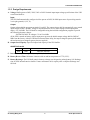
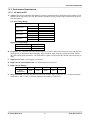
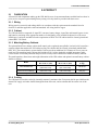
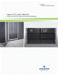
Liebert® GXT3™
6000VA RTL630 Rack-Tower model
GUIDE SPECIFICATIONS
1.0 GENERAL
1.1
SUMMARY
This specification shall define the electrical and mechanical characteristics and requirements for a continuousduty, single-phase, solid-state uninterruptible power system (UPS). The UPS shall provide high-quality AC power
for sensitive, electronic equipment loads. The UPS is not designed to support large inductive or half-wave
rectified loads, for example: motors, compressors, vacuum pumps, electric drills, laser printers and hair dryers.
1.2
STANDARDS
The UPS shall be designed in accordance with applicable sections of the current revision of the following
documents. Where a conflict arises between these documents and statements made herein, the statements in this
specification shall govern.
208V Nominal Units
UL Standard 1778, c-UL
CSA 22.2 No. 107.1
NEMA Type 1 Enclosure
FCC Part 15, Class A
CISPR22 Class A (RFI)
IEC 61000-3-12 (Harmonics)
IEC/EN/AS 62040-2 2nd Ed (Cat 2 - Table 6):
EN61000-4-2, Level 4, Criteria A
EN61000-4-3, Level 3, Criteria A
EN61000-4-4, Level 4, Criteria A
EN61000-4-5, Level 3, Criteria A
EN61000-4-6
ANSI C62.41, Category A
EN61000-4-5, Level 3, Criteria A
RoHS (6 by 6)
ISTA Procedure 1A
SL-23190_REV0_08-10
1
Guide Specifications
Liebert GXT3-6000RTL630
1.3
SYSTEM DESCRIPTION
1.3.1 Modes of Operation
The UPS shall be designed to operate as a true on-line double conversion system in the following modes:
A. Normal - During normal operation, utility power shall provide energy to the UPS. The filters, the power
factor correction circuit and the inverter shall process this power to provide computer-grade power to
connected loads. The UPS shall maintain the batteries in a fully charged state.
B. Battery - The UPS shall enter Battery mode if there is an extreme power surge, extreme power sag or utility
failure. The battery system shall supply power through the DC-to-DC converter to the inverter to generate
computer-grade power for the connected load.
C. Recharge - When the UPS is supplied with qualified utility power, the UPS shall charge connected internal
and optional external battery cabinets (if connected).
D. Internal Bypass - Bypass mode shall provide an alternate path for utility power to the connected load in the
unlikely event of a UPS malfunction, such as overload, overtemperature or an internal circuit failure.
E. Automatic Restart - Upon restoration of utility power after a utility outage and complete battery discharge,
the UPS shall be able to automatically restart and resume supplying power to the critical load based on the
settings in the supplied configuration program.
SL-23190_REV0_08-10
2
Guide Specifications
Liebert GXT3-6000RTL630
1.3.2 Design Requirements
A. Voltage: Shall operate at 208V, 220V, 230V or 240V. Nominal input/output voltage specifications of the UPS
at rated load shall be:
Input
The UPS shall automatically configure itself to operate at 208V, 50/60Hz input source. Input wiring must be
2-wire plus ground (L1, L2, G).
Output
Output voltage shall be present at terminals L1 and L2. The output voltage shall be automatically set to match
input voltage of 208V, 50/60Hz. Voltage is measured between L1-L2 (auto sensing to match input phase
angle): +5%, 60/50Hz. The UPS shall be configurable using the included configuration program to provide
the following alternate voltages:
208/220/230/240V, all voltages ±3% at 50 or 60Hz.
(If the UPS is started on battery with no input power present, the default output voltage shall be 208VAC,
60Hz from the factory. After the UPS has been started from utility, the output voltage/frequency shall match
the last known input voltage/frequency that was applied.)
B. Output Load Capacity: Specified output load capacity of the UPS shall be:
6000RTL630 model
VA
Watts
VAC Output
6000
4200
208 / 220 / 230 / 240
C. Internal Battery: Valve-regulated, non-spillable, lead acid cells.
D. Battery Reserve Time: Minimum 4 minutes with an ambient temperature of 77°F (25°C).
E. Battery Recharge: The UPS shall contain a battery recharge rate designed to prolong battery life. Recharge
time for UPS internal batteries shall be 3 hours maximum to 90% capacity after a complete discharge into
full load.
SL-23190_REV0_08-10
3
Guide Specifications
Liebert GXT3-6000RTL630
1.3.3 Performance Requirements
1.3.3.1 AC Input to UPS
A. Voltage: The point at which the UPS transfers to battery operation shall be dependent on the amount of load
that the UPS is supporting. The UPS shall operate from the following voltage ranges without drawing power
from the batteries:
Low Line Voltage Range
Low Line Voltage
100% to 91%
90% to 71%
70% to 31%
30% to 0%
GXT3-6000RTL630
L/L Transfer
L/L Comeback
L/L Transfer
L/L Comeback
L/L Transfer
L/L Comeback
L/L Transfer
L/L Comeback
176 ± 5.0VAC
188 ± 5.0VAC
159 ± 5.0VAC
171 ± 5.0VAC
139 ± 5.0VAC
151 ± 5.0VAC
100 ± 5.0VAC
112 ± 5.0VAC
High Line Voltage Range
High Line Voltage
208V Models
High Line Transfer
High Line Comeback
280 ± 5.0VAC
268 ± 5.0VAC
B. Frequency: The UPS shall auto-sense input frequency of 50Hz or 60Hz when first powered up and shall use
this frequency as the default output frequency. Once started the input frequency operating window shall be
40-70Hz without going to batteries. The UPS shall be capable of cold start with a default output frequency of
60Hz.
C. Input Power Factor: >0.99 lagging at rated load.
D. Input Current reflected distortion: 3% THD maximum at rated load.
E. Input Current Ratings:
UPS Model #
VA
Watt
Hz
VAC
Amp
GXT36000RTL630
6000
4200
50/60
208
30
F. Surge Protection: The UPS shall utilize metal oxide varistors (MOVs) rated at 175V, 150 Joules minimum
connected L1 and L2; 300V, 150 Joules minimum connected L1-G and L2-G.
SL-23190_REV0_08-10
4
Guide Specifications
Liebert GXT3-6000RTL630
1.3.3.2 AC Output, UPS Inverters
A. Voltage Configuration: 50/60Hz, single-phase, 2-wire-plus-ground.
Default setting 120/208V. Output L1 and L2 voltage shall be selectable via the included UPS configuration
program. Optional settings shall be 208V, 220V, 230V or 240V.
Note: At 100/200V setting, the UPS shall be derated to 80% of the rated 120/208V capacity; at 110/220V, the
UPS shall be derated to 90% of the rated 120/208V capacity.
B. Voltage Regulation:
L1-L2: ±2% steady state.
C. Frequency Regulation: ±3.5Hz synchronized to utility / mains.
±0.1Hz free running or on battery operation.
D. Frequency Slew Rate: 1.0Hz per second maximum
E. Load Power Factor Range: 0.65 lagging to 1.0 (unity)
F. Voltage Distortion: Sinusoidal Waveform; ≤3% total harmonic distortion (THD) into a 100% linear load;
≤5% THD into a 100% non-linear load with a crest factor ratio of 3:1.
G. Inverter Overload Capability:
Overload Percent
Duration Inverter shall support rated load
105% to 130%
131% to 150%
151% to 200%
>200% (impact load)
1 minute
10 seconds
1 second
At least 5 cycles
H. Voltage Transient Response: ±7% on-line or Battery mode for 0-100-0 % loading of the UPS, ±4% on-line
or Battery mode for 20-100-20 % loading of the UPS.
I. Transient Recovery Time: To nominal voltage within 166 milliseconds.
J. Efficiency: 92% AC-AC
SL-23190_REV0_08-10
5
Guide Specifications
Liebert GXT3-6000RTL630
1.4
ENVIRONMENTAL CONDITIONS
A. Ambient Temperature
Operating: 32°F to 104°F (0°C to 40°C) for altitudes 0 to 5,000 feet (0 to 1500 meters) above sea level.
32°F to 95°F (0°C to 30°C) for altitudes 5,000 to 10,000 feet (1500 to 3000 meters) above
sea level.
Storage: 5°F to 122°F (-15°C to +50°C)
GXT3-240VBATTUL and GXT3-240BATKIT: 68°F (20°C) for optimum battery storage.
Battery systems should not be stored for extended periods above 77°F (25°C)
B. Relative Humidity
Operating: 0 to 95% non-condensing.
Storage: 0 to 95% non-condensing.
C. Altitude
10,000ft. (3,000m) max, without power derating when operated within the temperature specified in Section
1.4, Item A. Ambient temperature shall be derated by 9°F (5°C) for each additional 1600ft. (500m) above
10,000ft. (3,000m).
D. Audible Noise
Noise generated by the UPS under normal operation shall not exceed 55dBA when measured at 3.2ft. (1m)
from the surface of the UPS.
E. Electrostatic Discharge
The UPS shall be able to withstand an electrostatic discharge compliant to EN61000-4-2, level 4, Criteria A,
without damage and shall not affect the connected load.
1.5
USER DOCUMENTATION
The specified UPS system shall be supplied with a Safety Warning Sheet. The UPS and Configuration Program
user manual shall be on an included CD. The user manual shall include installation drawings and instructions, a
functional description of the equipment with block diagrams, safety precautions, illustrations, step-by-step
operating procedures, general maintenance guidelines, troubleshooting information and product specifications.
1.6
WARRANTY
The UPS shall be warranted against defects in materials and workmanship for two (2) years. Optional one (1) and
three (3) year full coverage extended warranties shall be available from Emerson Network Power.
1.7
QUALITY ASSURANCE
1.7.1 Manufacturer’s Qualifications
More than 30 years experience in the design, manufacture and testing of solid-state UPS systems. The
manufacturer shall be certified to ISO 9001:2008.
1.7.2 Factory Testing
Before shipment, the manufacturer shall fully and completely test the system to ensure compliance with the
specification. These tests shall include operational discharge and recharge tests on the internal battery to ensure
performance.
SL-23190_REV0_08-10
6
Guide Specifications
Liebert GXT3-6000RTL630
2.0 PRODUCT
2.1
FABRICATION
All materials and components making up the UPS shall be new, of current manufacture and shall not have been in
prior service except as required during factory testing. All relays shall be provided with dust covers.
2.1.1 Wiring
Wiring practices, materials and coding shall be in accordance with the requirements the standards listed in
Section 1.2 and other applicable codes and standards. All wiring shall be copper.
2.1.2 Cabinet
The UPS unit shall be composed of: input PFC converter, battery charger, input filter and internal bypass circuit;
and batteries consisting of the appropriate number of sealed battery cells; and shall be housed in a rack-tower
NEMA type 1 enclosure and shall meet the requirements of IP20. The UPS cabinet shall be cleaned, primed and
painted RAL 7021 Black.
2.1.3 Matching Battery Cabinets
The optional Rack-Tower battery cabinet shall contain valve-regulated, non-spillable, lead acid cells, housed in a
separate cabinet that matches the UPS cabinet styling. The cabinet shall be cleaned, primed and painted Black
RAL 7021. The external battery system shall be sized to provide an additional 9-11 minutes of reserve power at
rated load. The matching battery cabinet shall include an 18" (0.45m) detachable, molded interconnect cable,
circuit breaker overcurrent protection and provisions for daisy-chain connection of additional battery cabinets.
The model numbers, dimensions and weight information of the UPS cabinet and optional external battery cabinet
shall be as follows:
Model
GXT3-6000RTL630
GXT3-240VBATTUL
(Optional External Battery)
Rack Dimensions
W x D x H, in. (mm)
Tower Dimensions
W x D x H, in. (mm)
16.9 x 22.6 x 8.5
(430 x 574 x 217)
16.9 x 22.6 x 5.1
(430 x 574 x 130)
8.5 x 22.6 x 16.9
(217 x 574 x 430)
5.1 x 22.6 x 16.9
(130 x 574 x 430)
Weight
lb. (kg)
138 (62.5)*
94.8 (43)*
* Specified weights include the standard two (2) internal battery kits, Part Number GXT3-240BATKIT.
2.1.4 Cooling
The UPS shall be forced air cooled by internally mounted, continuous fans. Fan power shall be provided from the
internal DC supply. Air intake shall be through the front of the unit, and air exhaust shall be out the rear of the
unit.
SL-23190_REV0_08-10
7
Guide Specifications
Liebert GXT3-6000RTL630
2.2
COMPONENTS
2.2.1 Input Converter
2.2.1.1 General
Incoming AC power shall be converted to regulated DC power by the input converter for supplying DC power to
the inverter. The input converter shall provide input power factor correction (PFC) and input current distortion
reduction.
2.2.1.2 AC Input Current Limit
The input shall use the power necessary to operate the load attached to the output before going to batteries. The
UPS shall not use electronic input current limiting. The UPS shall include a 2-pole switch-type 60A input
breaker.
2.2.1.3 Input Protection
The UPS shall have built-in protection against undervoltage, overcurrent and overvoltage conditions including
low-energy lightning surges, introduced on the primary AC source. The 208VAC models shall sustain input
surges without damage per criteria listed in ANSI C62.41 Cat. A.
2.2.1.4 Battery Recharge
The UPS shall contain a battery recharge rate designed to prolong battery life. The battery shall be constant
current charged to restore capacity, then shall be constant voltage charged to maintain the battery in a fully
charged state. Recharge time for the internal battery shall be 3 hours maximum to 90% capacity (full load
discharge rate). There shall be DC overvoltage protection so that if the DC voltage exceeds the pre-set limit, the
inverter shall shut down automatically and the critical load shall be transferred to internal bypass.
2.2.2 Inverter
2.2.2.1 General
The UPS inverter shall be of a pulse-width-modulated (PWM), IGBT design capable of providing the specified
AC output. The inverter shall convert DC power from the input rectifier output or the battery into precise
sinewave AC power for supporting the critical AC load.
2.2.2.2 Overload
The inverter shall be capable of supplying current and voltage for overloads exceeding 100% and up to 201% of
full load current. A visual indicator and audible alarm shall indicate overload operation. For greater currents or
longer time duration, the inverter shall have electronic current-limiting protection on the output to prevent
damage to components. The inverter shall be self-protecting against any magnitude of connected output overload.
Inverter control logic shall sense and disconnect the inverter from the critical AC load without the requirement to
clear protective devices.
2.2.2.3 Inverter DC Protection
The inverter shall be protected by the following DC shutdown levels:
DC Overvoltage Shutdown
DC Undervoltage Shutdown (End of Discharge)
2.2.2.4 Output Frequency
An oscillator shall control the output frequency of the UPS. The inverter shall maintain the output frequency to
±0.1Hz of nominal frequency during Battery mode, Frequency Converter mode or when otherwise not
synchronized to the utility/mains source.
2.2.2.5 Output Protection
The UPS inverter shall employ electronic current limiting circuitry for protection during Normal mode and
battery operation and shall employ input circuit breaker protection during Bypass mode operation.
SL-23190_REV0_08-10
8
Guide Specifications
Liebert GXT3-6000RTL630
2.2.3 Display and Controls
2.2.3.1 General
The UPS shall be provided with a microprocessor-based control and a status display section designed for
convenient and reliable user operation. The monitoring functions such as status and alarm indicators shall be
displayed on a front-panel LED display.
2.2.3.2 System Indicators
The UPS shall include five individual LED status indicators and three rows of LEDs to indicate UPS load and
battery capacity. An audible alarm shall be used in conjunction with the visual indicators to indicate to the
operator a change in UPS operating status.
All audible alarms can be silenced, with the exception of low battery, bypass reminder and missing batteries at
startup alarms. Once silenced, the audible alarm shall not sound until a new alarm condition is present. Standard
LED indicators are described below:
Load Level indicators: 10 total: 4 green and 1 amber, for each of the L1 and L2 outputs. The Load
Level indicators shall display the approximate load level at all times.
Battery Capacity indicators: 5 green LEDs. The Battery Capacity LEDs shall display the approximate
level of battery reserves.
Fault indicator: 1 red LED. The Fault indicator LED shall illuminate if the UPS detects an internal
problem. One or more of the Battery Capacity indicators may be illuminated to aid in diagnostics.
AC Input indicator: 1 green LED. The AC Input indicator LED shall be illuminated when utility power
is available and falls within the input specification.
UPS ON indicator: 1 green LED. The On Inverter indicator LED shall be illuminated when the UPS
inverter is operating and supplying power to connected loads.
On Bypass indicator: 1 amber LED. The On Bypass indicator LED shall be illuminated when the
bypass source is supplying power to connected loads.
On Battery indicator: 1 amber LED. The On Battery indicator LED shall be illuminated when the AC
Input is out of the acceptable operating range.
2.2.3.3 On-Standby-Off Controls
UPS startup and shutdown operations shall be accomplished by the ON and STANDBY push buttons on the front
panel of the UPS. The ON push button shall be a means to turn the UPS on and shall also serve as a means to
manually test the battery. The STANDBY push button shall allow manual transfers of the load from the inverter
to bypass power. Pressing the STANDBY push button in Bypass or Battery mode shall completely shut down the
UPS and its connected load.
2.3
ON-LINE BATTERY TEST
The UPS shall feature an automatic battery test with the factory default test interval set at every 2 weeks. The
battery test shall ensure the capability of the battery to supply power to the inverter while loaded. If the battery
fails the test, the UPS shall display a warning alarm to indicate the internal batteries need replaced and resume
operation without disturbing the load. The battery test feature shall be user accessible by the push button on the
front of the unit.
SL-23190_REV0_08-10
9
Guide Specifications
Liebert GXT3-6000RTL630
2.4
BYPASS
2.4.1 General
A bypass circuit shall be provided as an integral part of the UPS. The bypass shall have a make-before-break
transfer, shall have a maximum detect and transfer time of 4-6 milliseconds and shall be a double-pole device.
The bypass circuit shall be designed to ensure the simultaneous transfer of the L1 and L2 poles. The bypass shall
be configured to wrap around the PFC converter, battery charger, DC-DC converter, inverter and battery. The
bypass circuit shall use the rear-panel mounted UPS input circuit breaker and route bypass power through the
UPS input filters and surge suppression circuit. The bypass circuit default position shall be in the Bypass mode
(utility).
2.4.2 Automatic Transfers
The transfer control logic shall activate the bypass automatically, transferring the critical AC load to the bypass
source, after the transfer logic senses one of the following conditions:
UPS overload
UPS overtemperature
PFC failure
Inverter failure
DC bus overvoltage
Once the overload condition is reduced, the load shall be automatically transferred back to inverter power. An
overtemperature requires manual transfer back to inverter power after cooling.
2.5
INTERNAL BATTERY
Valve-regulated, non-spillable, lead acid cells shall be used as a stored-energy source for the specified UPS
system. The battery kit shall be internal to the UPS cabinet and sized to support the inverter at rated load and
power factor with an ambient temperature of 77°F (25°C) for a minimum of 5 minutes reserve time. The expected
life of the battery shall be 3-5 years or a minimum 250 complete discharge cycles at ambient temperature of 77°F
(25°C). To promote battery service life and eliminate over-discharge of the battery, the end-of-discharge DC
shutdown voltage shall be automatically adjusted by the microprocessor based upon the percentage load at the
onset of battery operation.
2.6
OUTPUT DISTRIBUTION
Output distribution shall be integral to the UPS cabinet and located on the rear of the unit. The output distribution
shall provide the capability to re-configure the UPS input and output connections via a removable sheet metal
power distribution box. Distribution options shall be available with break-before-make maintenance bypass
switch to allow for complete shutdown and isolation of the UPS for service without powering down the
connected loads. Maximum transfer time of the maintenance bypass switch shall be 4-6ms. Standard output
distribution configurations shall be:
Distribution
Model
Utility Input
Connection
Output Load Connections
Maintenance
Bypass
PD2-L630
L6-30P
Output - (2) L6-30R, (2) L6-20R
Included
SL-23190_REV0_08-10
10
Guide Specifications
Liebert GXT3-6000RTL630
2.7
ON-BOARD COMMUNICATION
The Liebert GXT3 shall offer multiple communication options such as:
A. USB: All models shall work with the Power Management system in Microsoft® Windows® 2000, Windows
XP, Windows Vista®, Linux and Mac OS® X.
B. Remote Emergency Power Off (REPO): The UPS shall be equipped with rear-panel terminal connections
for interface with either a normally open (N.O.) or normally closed (N.C.) field-supplied switch. The remote
emergency power off function shall allow the user to disable all UPS outputs in an emergency situation.
Connections must not exceed NEC Class 2 limits. Activation of the REPO circuit shall disable the UPS until
the following occurs:
REPO contacts are reset.
User restart of the UPS using the front control panel.
C. Terminal Block Communication: includes 8 pins
Pin
1&
2
3&
4
5&
6
7&
8
Definition
Low Battery Warning
On Battery Warning
Any Mode Shutdown
Battery Mode Shutdown
D. Liebert IntelliSlot® Port
Simultaneous communication shall be available via terminal block (EPO), USB and Liebert IntelliSlot.
2.8
LIEBERT INTELLISLOT COMMUNICATION OPTIONS
The UPS shall include one Liebert IntelliSlot communication port to allow the operator to field-install optional
Liebert IntelliSlot communication cards. Liebert IntelliSlot cards may be installed during any state of UPS
operation (On, Standby or Off states). Available Liebert IntelliSlot options are described below.
Liebert IntelliSlot Web Card (IS-WEBCARD)
The optional Liebert IntelliSlot Web Card shall deliver SNMP and Web management to the UPS when
connected to any 10 or 100 Mbit Ethernet network. The card shall support 10 and 100 Mbit Ethernet and
shall provide for in-the-field upgrade of SNMP firmware. The kit shall include the Liebert IntelliSlot card,
MIB, configuration cable and user manual. Once the card is installed, serial communication shall be disabled
in the DB9F connector; however, the photo-coupler signals (On Battery and Low Battery) shall remain
active.
Liebert IntelliSlot Relay Interface Card (RELAYCARD-INT)
The optional Liebert IntelliSlot Relay Interface Card shall provide contact closure for remote monitoring of
alarm conditions in the UPS, delivering signals for On Battery, On Bypass, Low Battery, Summary Alarm,
UPS Fault and On UPS. The contacts shall be rated for 24VAC or 24VDC at 1A. Connection shall be to a
DB25F connector with cable provided by the end user.
SL-23190_REV0_08-10
11
Guide Specifications
Liebert GXT3-6000RTL630
2.9
LIEBERT GXT3 CONFIGURATION PROGRAM
An included Microsoft Windows-based (Windows 95 or later) Configuration Program and cable shall allow
configuration of UPS features and operating parameters to meet specific application requirements, if required.
Options that are configurable via this program shall include:
Select one of four output voltages to match input voltages of 208, 220, 230 or 240.
Enable / Disable Auto-Restart.
Select frequency converter operation with a fixed output frequency of 50 or 60Hz. Bypass is disabled
during Frequency Converter mode.
Set the Low Battery Warning alarm time from 2 to 30 minutes.
Disable the Auto-Battery test.
Set the Auto-Battery test interval to 7, 14, 21 or 28 days.
Select the number of external battery cabinets connected to the UPS to adjust the remaining run-time
calculations reported by the UPS Liebert software products.
Modify the shutdown setting of the Any Mode Shutdown.
SL-23190_REV0_08-10
12
Guide Specifications