1
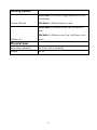
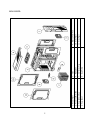
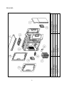
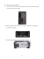
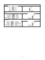
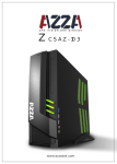
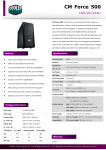
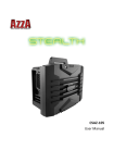
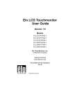
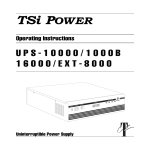
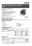
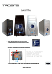
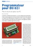
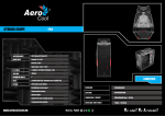
CSAZ-‐8000B/CSAZ-‐8000W/CSAZ-‐8000GM CSAZ-‐8100B User Manual Contents Chapter 1 Product Introduction 1.1 Specifications …………………………………………………..…………………...03-‐06 1.2 Accessories …..……………………………………………………………………………… 07 Chapter 2 Installation Guide 2.1 Side Panel Disassembly …..…………………………………………………………… 08 2.2 Motherboard Installation …..…………………………………………………….08-‐09 2.3 5.25” Device Installation ……..…………………………………………………..09-‐10 2.4 3.5” Device Installation …………..……………………………………………….11-‐12 2.5 2.5” Device Installation ……………..………………………………………………….13 2.6 PSU Installation …………………………..………………………………………………..14 2.7 Fan Installation ………………………………..……………………………………………15 2.8 Water Cooling Installation …………………..………………………………………..16 2.9 Front Panel Control & I/O Installation ….…………………………………..17-‐19 Chapter 1 Product Introduction 1.1 Specifications Model Model Name NOVA 8000 Model Number CSAZ-‐8000B/CSAZ-‐8000W/CSAZ-‐8000GM Model Name ZEN 8100 Model Number CSAZ-‐8100B Specification Type ATX Full Tower NOVA 8000: Black/White/Gun Metal Color ZEN 8100: Black/Black Material SECC Steel Side Panel Window Yes With Power Supply No CPU Cooler Compatibility Up to 190mm Motherboard Compatibility E-‐ATX, Full ATX, Micro ATX Power Location Rear Bottom Expansion External 5.25" Drive Bays 4 Internal 2.5" Drive Bays 3 Internal 3.5" HDD Slot 6 Easy Swap 3.5" HDD Slot 2,6 (option) Expansion Slots 9 NOVA 8000: 2x USB 3.0, 2xUSB 2.0, HD Audio Front Ports ZEN 8100: 2x USB 3.0, 4xUSB 2.0, HD Audio 3 Cooling System NOVA 8000: 1x120mm Orange/Red/Blue LED fan in the front 120mm LED Fan ZEN 8100: 1x120mm Red fan in rear NOVA 8000: 2x120mm on the Top, 1x120mm in Rear ZEN 8100: 2x120mm on the Top, 1x120mm in the 120mm Fan front Physical Spec Dimensions (HxWxD) 21.6"x8.7"x22.6" (HxWxD) Weight 30 lbs 4 5 5.! ! Case! 6.! ! Backplane! 7.! ! 3.5”!Drive!Tray! 8.! ! Dust!Filter! 1.! ! Front!Panel! 2.! ! Front!120mm!Fan! 3.! ! Top!120mm!Fan! 4.! ! Top!Panel! ! 11.! ! Side!Panel! 10.! ! Side!Panel! 9.! ! Rear!120mm!Fan! ! NOVA 8000: 6 5.! ! Case! 6.! ! Backplane! 7.! ! 3.5”!Drive!Tray! 8.! ! Dust!Filter! 1.! ! Front!Panel! 2.! ! Front!120mm!Fan! 3.! ! Top!120mm!Fan! 4.! ! Top!Panel! ! 11.! ! Side!Panel! 10.! ! Side!Panel! 9.! ! Rear!120mm!Fan! ! ZEN 8100: 1.2 Accessories Accessory Box Contents: -‐ User Manual × 1 -‐ Screw Bag × 1 Standoff Screw for 2.5” HDD For M/B 5H-‐6#*4-‐ 6#*6.5HCu M3*5 20PCS Plastic thumb Screw for screws Power Supply 6#-‐32 6#6HW-‐TC Screw HDD 3*8*8PWA 6*5KM 10PCS Screw for 3.5” 24PCS 4PCS Cable Ties Cable Ties L=120mm L=150mm 10PCS 4PCS 3PCS Plastic Standoff For E-‐ATX M/B 3PCS 7 3PCS Chapter 2 Installation Guide 2.1 Side Panel Disassembly 1. To take off the side panel, remove the thumb screws from the back of the case, then pull the side panel toward the back to remove it. 2. To place the side panel back, align the side panel with the hook holes and slide the panel toward the front, then secure the panel with the screws. 2.2 Motherboard Installation 1. Install the I/O panel that comes with your motherboard package. 2. Aim at the holes on the motherboard, and secure the standoffs on the motherboard tray. 8 3. Align the holes of the motherboard with the motherboard tray, then secure the motherboard with the provided screws. Note: Instructions on CPU, RAM and any peripheral installations are not included in this manual. Please refer to your motherboard and/or other manuals for related mounting instructions and troubleshooting. 2.3 5.25” Device Installation For NOVA 8000: 1. Press the latch and remove the 5.25” drive cover from the chassis by pushing inside out, and place the 5.25” device into the drive bay. 9 For ZEN 8100: 1. Open the upper door of the front panel. 2. Remove the 5.25” drive cover from the chassis by pushing inside out, and put the 5.25” drive into the drive bay. 3. Match the ODD drive holes with the drive cage. Then turn the knob clockwise to secure the drive cage. 10 2.4 3.5” Device Installation 1. As shown below, pull the latch on the side panel lightly. 2. Push the latch of the drive bay to the right hand side, and take out the 3.5” drive tray. 3. Place the HDD into the drive bay and secure it on the bottom of the tray with provided screws. Reverse the steps above to place the HDD tray in the device cage. 11 4. Find the 4-‐pin Molex on the power supply and connect it to the backplane. Connect the backplane to the motherboard with SATA cables. Note: User can choose the direction for the 3.5” drive cage. This will help the u ser to arrange the chassis placement flexibly. Please refer to the pictures below for further information. 12 2.5 2.5” Device Installation The unit supports 3 2.5” device installations. 2 devices on the side of the 5.25” drive cage, and 1 device under the 3.5” drive cage. 1. Gently pull the latch to open the side panel. 2. Place the 2.5” device in the proper location as shown below, and secure it with provided screws. 3. rd For the 3 position, release the screw on top of the 3.5” device cage, and remove the cage. Put the 2.5” device on the bottom side of the bracket as shown below, and secure the device with provided screws. 13 2.6 PSU Installation 1. Place the power supply in its proper location and secure it with provided screws. (Screw holes enable the user to secure two sides of the PSU) 2. Simply route the cables behind the motherboard tray and power cables with the provided cable ties. 3. To optimize performance it is recommended that the washable dust filter underneath the power supply be cleaned on a regular basis. Simply pull out the dust filter, rinse with water, and slide it back after the dust filter is dried. 14 2.7 Fan Installation Bottom Fan Installation 1. Remove the 6 screws as shown below, and then remove the bottom bracket. 2. Install the fan inside the chassis and secure the screws from the bottom side. User is able to install maximum two 120mm fans on the bottom panel. Top Panel Fan Installation The unit comes with two 120mm fans on the top already. 1. Remove the screws on the back of chassis and open the top panel. 2. Install fans on the top and secure it on the top with provided holes. 15 2.8 Water Cooling Installation To install an external water cooling system, use the pre-‐drilled holes located 1. in the back to connect the tubes. 2. A 360 mm radiator may be installed on the top of the bottom unit using the pre-‐drilled screw holes. 3. The bottom panel is able to install a 240mm radiator. 16 2.9 Front Panel Control & I/O Installation Front Panel Control is for NOVA 8000 only: ! Please refer to the following table for front panel control & I/O ports 4 1 2 5 7 3 6 8 9 Item Description Item Description 1 Power on/off 2 Reset 3 Fan speed control +/-‐ 4 Power LED 5 HDD Activity LED 6 Fan Speed LED 7 USB 3.0 port 8 USB 2.0 port 9 Audio & Mic ! The chassis provides a “Fan speed control function” which supports up to 5 chassis fans, User presses “+” symbol to speed up and “-‐“ symbol to speed down the chassis fan speed. The function provides 4 sections to control fan speed from 40% to 100%, and LED brightness will be turned on by corresponding fan speed. ! Please refer to the following step to install the chassis fan. 17 1. Connect the 4-‐pin power connector to the power supply. 2. Remove the top cover and connect the 3-‐pin fan connector to the control board. ! Please refer to the following illustration of front I/O connector and your motherboard user manual. Front I/O Connector Motherboard Case cable connector USB 3.0 18 USB 2.0 AC’97 HD Audio 19