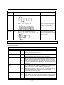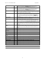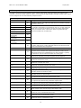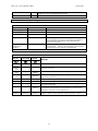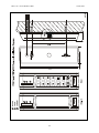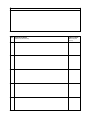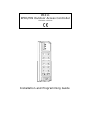
1
PR311 RFID/PIN Outdoor Access Controller Firmware v102.00 Installation and Programming Guide PR311 v1.0 fv102 EN Rev.E.DOC 1 TABLE 1 2 3 4 5 6 7 10/22/2007 OF CONTENTS Table of Contents Glossary and Terms Introduction 3.1 Designed Function 3.2 Main Features 3.3 Operation in the Integrated Access System 3.4 Stand-alone Operation Functional Description 4.1 Users 4.2 Group of Users 4.3 User Identification 4.4 ARMED and DISARMED Modes 4.5 Arming and Disarming of the Controller (Rearming) 4.6 Unlocking a Door 4.7 Option: Deactivate Door Release After Door Open 4.8 Option: Access When Controller Armed (AWA Privilege) 4.9 Duress Function 4.10 Facility Code 4.11 Option: Timed Lock-out of the Controller 4.12 System Flags 4.13 Operation with External PRT Series Reader 4.14 Operation with XM-2 I/O Extension Module 4.15 Alarms 4.16 Inputs 4.17 Outputs 4.18 Acoustic and Optical Signals Programming 5.1 Memory Reset Procedure - Programming MASTER Identifier 5.2 User Programming 5.2.1 User Programming Commands 5.3 Installer Programming 5.3.1 Installer Programming Functions Installation and Setup Guidelines Appendix 2 2 3 5 5 5 5 6 6 6 6 6 7 7 8 8 8 8 8 8 8 9 9 9 10 12 13 14 14 14 14 16 16 19 20 PR311 v1.0 fv102 EN Rev.E.DOC 10/22/2007 2 GLOSSARY AND TERMS Identifier The method or means which is used to identify a person. It can be a proximity car, a PIN code, a finger template etc. In some cases Identifier may consist of two or more of item required for a single identification procedure. For example when the option [Card and PIN] is active then Identifier=Card+PIN. Stand-alone Mode The situation when device operate without physical connection to any Host device or when such connection exists but it is used only for uploading/downloading of data to/from a unit. Integrated Access Control System (IACS) The access control system which consists of one or more access controllers connected to a communication medium and managed from a Host device. The Host device plays a special role in such systems while adding some functionality to them. Without the Host device the functionality of a system deteriorates partly or completely. Networked Access System Same meanings as Integrated Access System. Roger Access Control System (RACS) The access control system which consists of PR series access controllers developed and manufactured by the Roger. Host Device The electronic equipment which is used to expand functionality of the access system. In the RACS system a Host unit can be the CPR32SE host controller or the PC with special software which is used for online control of the access system. Door Mode The method which is used to control door release device. The PR311 offers: Normal, Unlocked, Locked and Conditional Unlocked door modes. Identification Mode The method which is used for identification of users. The PR311 offers: Card and PIN, Card or PIN, Card only and PIN only identification modes. Facility Code The common part of card codes which characterize all cards used in the particular access system. Door Release or Door Lock The electric device which is used to enable access to the controlled room or area. Typically it can be a door strike or a magnetic lock. Communication bus The physical medium which is used for exchange of data between various devices connected to it. The PR311 is equipped with two types of communication buses: the RS485 interface and the Clock & Data. System Flags Flags are logical registers which exist in controller’s memory. Each Flag represents a status of relevant situation which may occur in controller. Timers The function which automatically clears condition of some item (physical or virtual) after predefined time. The Timer function can refer to various elements of controller logic e.g. to outputs, time delays etc. Latch Mode Latch mode refers to situation when some element (e.g. output) changes its condition for unlimited time – till the moment when some other event will restore previous condition of given element. RS485 The electrical interface which is used by controller for communication with PC managing software and/or Host device (when operating in Integrated Access Control System). Communication with PC requires special communication converter. Actually Roger offers two converters for such purpose: UT-2 (RS232-RS485) and UT4 (TCP-RS485). Clock & Data Interface The electrical interface which is used by controller for communication with various equipment connected to it. The PR311 can operate with second PRT series reader and/or XM-2 extension module. Both device can be connected to the same Clock and Data lines and must have individual addresses (ID numbers). 3 PR311 v1.0 fv102 EN Rev.E.DOC 10/22/2007 XM-2 I/O Extension Module The external I/O extension module which can be connected to PR311 controller via Clock & Data lines. PRT Series Readers The family of PRT reader’s family developed and manufactured by Roger. Each member of PRT series readers can be connected to PR311 access controller via Clock & Data interface. Typically the remote reader is used for two-way door control. 4 PR311 v1.0 fv102 EN Rev.E.DOC 10/22/2007 3 INTRODUCTION 3.1 Designed Function The PR311 access controller has been designed for use in access control installations or systems as an outdoor access control device to enable user identification via EM 125 kHz UNIQUE standard proximity cards and/or PINs. The PR311 unit can operate stand-alone or as a part of integrated (networked) access control system. When controller operate as a stand-alone unit it independently (i.e. autonomously) controls the supervised door access point. In this mode controller doesn’t offer either event recording or time schedules (time tables). Programming of a unit can be done locally using its keypad and programming cards or remotely from PC. The connection to PC requires UT-2 programming interface and programming software (e.g. PR Master or PR Master Lt). The PR Master is used to administrate the Integrated Access Control System which consist of PRxx1 and PRxx2 access controllers (from Roger), the PR Master Lt is a reduced version the PR Master and is dedicated only for configuration of a single controller unit. If controller is a part of the Integrated Access Control System which is managed by the Host device the PR311 extends its functionality and enables definition of user access groups, time schedules and recording of events. The PR311 can be configured for operation with external XM-2 I/O Extension Module and external PRT series reader. The use of XM-2 adds two NO/NC type inputs and two relay outputs to the controller. The system setup utilizing an XM-2 module provides higher level of security for door access control system by separating its logical element (the controller unit) from the actuator element controlling the door lock (i.e. the door lock relay). The use of external PRT reader enables two-way door control. Note: If programmed from PC the PR311 requires RACS 4.2 or higher. 3.2 Main Features Built-in EM 125kHz card reader back-light keypad 1.000 Users with Card and/or PIN User indexing (ID indexed user records) System settings stored in nonvolatile memory Three programmable inputs Three programmable outputs (one relay output and two transistor outputs) Two-way door control (requires additional PRT reader to form a pair) Integration with the Alarm System through I/Os XM-2 I/O module support (add two inputs and two relay outputs to the controller) Programmed manually or from PC ABS casing with TAMPER CE mark Add-on features when operating in the Integrated Access Control System (with Host device) 3.3 256 access groups 32 time schedules for access level control Time schedules for Identification Mode and Door Mode 128 time periods per schedule Events recorded by Host (CPR32SE Host controller or PC with PR Master program in online mode) Operation in the Integrated Access System In this case the PR311 is a part of an Integrated Access Control System (IACS) which operate under control of the Host device. The Host device adds some extra functionality to entire access system. When the PR311 operates in the IACS users can be divided into 256 access groups, each group may have different access authorization controlled by a time schedule. The PR311 allows up to 32 time schedules which are used to control access and two special schedules – one of them controls the Identification Mode while the other controls the Door Mode. Events which occur in the IACS are stored by Host device. If the communication with the Host is broken the PR311 continues operation with time schedule settings which existed when communication disappeared. After communication with the Host resumes all clock related settings (e.g. time schedules) are refreshed and updated. 5 PR311 v1.0 fv102 EN Rev.E.DOC 3.4 10/22/2007 Stand-alone Operation In this case the PR311 access controller autonomously supervises door passage and doesn’t require any connection to the Host device. All users belong to the same group which has permanent access authorization regardless of time. Neither the Identification Mode nor Door Mode can be controlled by time schedules, events are not registered. 4 FUNCTIONAL DESCRIPTION 4.1 Users The PR311 can register up to 1000 users. Every user has its ID (identification) number from 001 to 999 and may have its card and PIN. The PR311 controller precludes assignment of the same cards or PINs for 2 different users. Users can be identified by cards, PINs or both methods simultaneously. The PIN codes may have from 3 to 6 digits and whenever entered must be followed by [#] mark which is used to mark the end of a code. The PR311 controller supports five types (classes) of users: MASTER, INSTALLER, NORMAL, TOGGLE and TOGGLE LTD. Each of the class has different authorization for programming, unlocking and rearming of a controller. Table 1: User types User Type ID number Description INSTALLER No ID Authorization for entry to the Installer Programming only. MASTER 000 Authorization for user programming commands, unlocking and rearming. TOGGLE ID=01…49 Authorization for unlocking and rearming. TOGGLE LTD ID=50…99 Authorization for rearming only. NORMAL ID=100…999 Authorization for unlocking only. Note: By default each User Programming Command requires the MASTER identifier; nevertheless installer can clear this request for some or for all of User Commands. 4.2 Group of Users When the PR311 controller operates in the stand-alone mode all users programmed to a unit belongs to the same group of users, as a result they have the same access authorization (i.e. access level) which doesn’t depends of a time - all users programmed to a unit have access to a controlled door. When the PR311 controller is a part of Integrated Access Control System controlled by the Host device, all the users can be divided into 256 groups and may have different access authorization. The access level of each group can be controlled by time schedule, the PR311 allows up to 32 different time schedules to be defined for a unit. 4.3 User Identification The PR311 recognize the users by means of theirs identifiers. Each user programmed to the controller may have card and/or PIN. The method which controller uses for user identification depends on the actual Identification Mode. The Identification Mode determines which kind of identifier (card, PIN or both) a user must use in order to be accepted by the controller. The PR311 enables following identification methods: Card only: controller accepts only cards PIN only: controller accepts only PINs Card or PIN: controller requires card or PIN, only one of them is necessary for a successful identification Card and PIN: controller requires card and PIN, both of them are necessary for a successful identification. Note: For Card and PIN mode user must read its card and enter its PIN, sequence doesn’t matter. 6 PR311 v1.0 fv102 EN Rev.E.DOC 4.4 10/22/2007 ARMED and DISARMED Modes The PR311 has two working operating modes: Armed and Disarmed mode. The actual controller’s operating mode is indicated on the dual color LED STATUS, which lights in red for Armed or green for Disarmed. Generally the Armed and Disarmed modes are dedicated for integration of the controller with the alarm system which protects the same room or area which is supervised by the access controller, nevertheless they can be used for any other control purpose which requires an On/Off control method. The integration with the alarm system (or another device or system) requires one output line to be configured to function no. 00 (Disarmed Mode) and one input line configured to input no. 13 function (Ready Status). The controller output line (function no. 00) indicates current operating mode of the controller, whereas the input line (function no. 13) verifies if the controlled system (or device) is ready to be armed (or set ON). Note: When the installer doesn’t define any controller’s input to the function no. 13, the controller assumes that the alarm system is always ready for arming and switches to armed mode unconditionally. Note: Either upon powering on or Memory Reset reader automatically enters the Armed mode. After exit from programming mode reader returns to arming mode (either Armed or Disarmed) it was before entry to the programming. 4.5 Arming and Disarming of the Controller (Rearming) The action changing the controller from Armed to Disarmed and back (i.e. reverse direction) is referred to hereinafter as REARMING. The term “arming” should be understood here as the action effecting a switch into the Armed mode, whereas the term “disarming” a switch into the Disarmed mode. Controller can be rearmed in few methods listed below: by by by by by by by by by an input line configured to function no. 03 (arming and disarming by steady switch) an input line configured to function no. 61 (arming and disarming by momentary switch) an input line configured to function no. 78 (disarming by momentary switch) an input line configured to function no. 79 (arming by momentary switch) the MASTER user (by use of the MASTER identifier) the TOGLLE user (by use of the TOGGLE identifier) the TOGGLE LTD user (by use of the TOGGLE LTD identifier) an interactive command from PC the Armed/Disarmed Schedule The rearming can be carried out either from the controller or from the external reader connected to the controller. Note: All methods listed above except first one can be used simultaneously to control Arm/Disarm mode of the controller. When any of the controller input is configured to function no. 3 (arming and disarming by steady switch) all other methods of rearming are inoperative. Reader rearming command can be issued by MASTER, TOGGLE or TOGGLE LTD users. To rearm the reader a MASTER and TOGGLE user is required to enter its identifier twice, whereas a TOGGLE LTD user needs to enter its identifier once. Example: Rearming the controller by using a TOGGLE identifier (when Card and PIN mode is active) Read your TOGGLE user card, enter your TOGGLE user PIN, once the identifier is accepted the LED SYSTEM starts flashing, read your TOGGLE user card or enter your TOGGLE user PIN, after last step the controller changes its arming mode (watch for the LED STATUS to change a color). Note: If the Card and PIN mode is active the first step of identification requires both elements (card and PIN) to be entered, in the second step controller requires only one method of identification (card or PIN). Example: Rearming the controller by using a TOGGLE identifier (when Card only mode is active) Read your TOGGLE user card, once the identifier is accepted the LED SYSTEM starts blinking, read your TOGGLE user card once again, after last step the controller changes its arming mode (watch for the LED STATUS to change color). 7 PR311 v1.0 fv102 EN Rev.E.DOC 10/22/2007 Note: If programmed the condition on the input line configured to function no. 13 can disable arming of a controller. 4.6 Unlocking a Door In order to unlock the door a user is obliged to enter his identifier. Whenever this happens the device activates LED SYSTEM (orange) for a moment and generates a short confirmation beep. If the entered identifier has authorization for entry controller energizes the door lock for the predefined time. The lock activation is signaled on LED OPEN (green), which remains ON for as long as the door lock is energized. When access to the supervised room is denied the reader generates error sound (long beep). The access to a room can be rejected in the following situations: 4.7 When entered identifier is unknown; When entered identifier belongs to the TOGGLE LTD class of users; When controller operates in Armed mode and the user which entered identifier has not an AWA Privilege assigned; When the input line configured to function no. 11 (Access Disabled) is in active condition; When access is disabled by relevant time schedule (this rule refers to operation in IACS) Option: Deactivate Door Release After Door Open Normally when this option is not set controller activates a door release device and keep it energized by entire predefined time (Installer Programming function [46][OT]). When this option is set door release device is triggered till the moment when controller recognize that door became open but not longer that time defined by function [46]. 4.8 Option: Access When Controller Armed (AWA Privilege) Normally when controller is Armed access to the controlled door is disabled for all types of users except the MASTER user. This rule can be changed by an option: Access When Armed (alternatively called: AWA Privilege). When this option is set user may enter the room when controller operates either in the Armed or in the Disarmed mode. The AWA Privilege can be set individually for each user programmed to the controller. The PR311 controller offers separate sets of programming commands, one for the users which are allowed for AWA Privilege and another for the users which are not granted with this privilege. 4.9 Duress Function If the user enters a PIN code which differs from its original form by +/- 1 on the last position of a code it will be treated as a DURESS entry. The DURESS PIN code is accepted by a controller as a normal valid one, the only difference is that entry of such code triggers the DURESS flag and activate the DURESS Flag output (when programmed). The recognition of DURESS codes can be disabled by the installer. When DURESS option is enabled all PINs programmed to a unit must differ one from each other by +/-1 on the last code position. (Default: Option Disabled) 4.10 Facility Code The Facility Code is a part of the entire card code and can be a number from 000 to 255. When Facility Code option is set controller accepts not only cards which are programmed to its memory but also all other cards which are characterized with the same Facility Code. As a result of the Facility Code option access can be granted to large number of users which are not programmed into a device. Typically, the Facility Option is used when controller is dedicated for installation were number of users exceeds one thousand. During configuration process installer can assign an AWA Privilege to a group of Facility cards so they card with Facility codes) will be able to open a door even when controller is armed. (Default: Option Disabled) 4.11 Option: Timed Lock-out of the Controller If the controller recognizes three consecutive attempts of entry of a non-valid identifier it will ignore all identifiers within next three minutes (cards and PINs). Option can be set or cleared by installer. 4.12 System Flags 8 PR311 v1.0 fv102 EN Rev.E.DOC 10/22/2007 Flags are logical registers which exist in controller’s memory. Each Flag represent a status of relevant situation which may occur on controller. For example if a user enters a DURESS PIN code this will activate (sets ON) the DURESS flag, when controller recognizes triggering of the TAMPER input it will trigger (sets ON) the TAMPER flag etc. The PR311 utilizes the following flags: AUX1 Flag LIGHT Flag TAMPER Flag DURESS Flag TROUBLE Flag Depending on a type of the Flag it can be set or cleared by various situations (see table below). Every Flag has assigned a Timer. The Timer specifies for what time the relevant Flag will remain active after it is set ON. The Flag Timer can be programmed in seconds [SS] or minutes [MM]. The Timers for AUX1 and LIGHT flags can be optionally programmed to a value SS=00 (operation in Latch mode), in this case once the Flag is set it will remain in ON mode for unlimited time till the moment when adequate command or other event will occur which will clear it. Table 2: System Flags Flag Latch Mode Setting methods Clearing methods AUX1 Yes SS=00 User command (function 31) From input line (code 71 and 73) User command (function 31) From input line (code 72 and 73) LIGHT Yes SS=00 User command (function 33) Input line (code 68 and 70) Function key (code F2) User command (function 33) Input line (code 69 and 70) TAMPER No Input line (code 08) Disarming of the controller DURESS No DURESS code entry Disarming of the controller TROUBLE No Lost of communication with XM-2 module AC Lost input (code 05) triggered Low Battery input (code 06) triggered Disarming of the controller Note: All Flags are automatically cleared in following situations: after controller’s restart, after entry to the Installer Programming or when controller is being programmed from a PC. 4.13 Operation with External PRT Series Reader The PR311 is capable to operate with external PRT series reader. If used the PRT reader enables two-way door control. The PRT reader should be connected to controller’s CLK and DTA lines and must have an address set to ID=0. The maximum distance between controller and the PRT reader is limited to 150m. 4.14 Operation with XM-2 I/O Extension Module The PR311 is capable to operate with external XM-2 I/O extension module. If used the XM-2 adds two inputs and two relay outputs to a controller. Each input and output of the XM-2 can be programmed on the same basis as internal inputs and outputs of a controller. The XM-2 should be connected to controller’s CLK and DTA lines and should have address set to ID=5. The maximum distance between a controller and the XM-2 extension module is limited to 150m. 4.15 Alarms The PR311 controller has been designed to detect and indicate the following alarm types: Forced Door Prealarm Door Ajar The alarm signaling is carried out over the dedicated output line. Each alarm can be signaled on separate output or alternatively the one output line can be configured to signal two or even three alarms. The alarm signaling the PR311 uses different signal modulation of an output, depending on alarm type (see table below). Alarm duration is ~3 minutes, regardless of alarm type. Each alarm can be stopped manually within 3 minutes from its start by using valid identifier. Additionally, a Door Ajar alarm is stopped as soon as the door is closed. If more than one alarm is triggered, the reader indicates the alarm with the highest priority. 9 PR311 v1.0 fv102 EN Rev.E.DOC 10/22/2007 Note: Forced Entry and Door Ajar alarms will occur only if the reader operates with a Door Open Contact. Table 3: Alarm signalling methods Alarm type Priority Signalling method Alarm situation (event) Forced Door High By cycles with the following sequence: Active - 4 sec., Pause - 4 sec. The door opened without use of a valid identifier. Prealarm Medium By cycles with the following sequence: Active - 1 sec., Pause - 1 sec. Three consecutive attempts to enter an unregistered (unknown) identifier (card and/or PIN). Door Ajar Low By cycles with the following sequence: Active - 1 sec., Pause - 1 sec., Active - 1 sec., Pause - 5 sec. After access has been granted and the door opened it is left ajar for the time exceeding the door open time setting. 4.16 Inputs The PR311 provides five logical inputs, three inputs are physically located on the PR311 itself and two on the remote XM-2 I/O extension module. Each input can be configured as NO or NC type and may have assigned function from a list below: Table 4: Input line functions Function Input OFF Door Contact Code 00 Selecting this function will disable decoding of this input; this function can be used for temporary input deactivation without disconnecting it physically from the triggering source. 01 Input is dedicated for a contact used to indicate that the corresponding door is open. Input activation generates a [Door opened] event, whereas input deactivation generates a [Door closed] event. 02 Input is dedicated for operation with a button which will be used to open the corresponding door without using any identifier. Activation of this input will activate the door lock for the same time period as after a standard [Access granted] event. This function is usually used to enable connection of a Request To Exit (REX) button. Activation/deactivation of the input generates an [Exit button ON]/[ Exit button OFF] event respectively. Exit Button Arm/Disarm Steady Switch Input is dedicated for operation with some types of switches which upon their activation make the controller go into Disarmed mode. When the switch is not active the controller will stay in Armed mode. 03 Note: Only one input on the PR311 controller can be configured to this function. When this function is selected any other methods of Arming/Disarming will be forbidden. 04 The only effect of activation and deactivation of this input is that it will be registered by the Host unit (when controller operates in Integrated Access System). This input is dedicated for auxiliary monitoring purpose and can be used to register condition of a switch or voltage applied to the input. 05 Input is dedicated for connection to an output line or a contact which is AUX Input AC Lost Description 10 PR311 v1.0 fv102 EN Rev.E.DOC 10/22/2007 used to indicate a loss of AC power supply. Each time this input is triggered it activates the TROUBLE flag timer which can further activate (if programmed) the TROUBLE output (code 70). Low Battery 06 Input is dedicated for connection to an output line or a contact which is used to indicate a loss of AC power supply. Each time this input is triggered it activates the TROUBLE flag timer which can further activate (if programmed) the TROUBLE output (code 70). 07 Each time this input is triggered controller activates the BELL Output (code 15). Input is dedicated for connection to a button used to indicate that somebody wants to enter the premises. 08 Input is dedicated for connection to a tamper-protection contact which indicates that an unauthorized person attempts to open the controller's case. Each time this input is triggered it activates the TAMPER flag timer which can further activate (if programmed) the TAMPER output (code 65). 11 Input is dedicated for connection to a switch or an output which when activated will disable access to the controlled door. 13 This input is dedicated for connection to an output line or to a switch which indicates that controller can be Armed. When this input is not triggered controller can not be armed. This input does not affect arming when it is carried out by input Arm/Disarm Steady Switch (code 03). 14 Triggering of this input will force activation of the door release. This input is dedicated to be connected to an emergency switch which when triggered will release door. As long as input is triggered door will be released. 61 Input is dedicated for connection to a button or an output which is dedicated to rearm the controller. Each time this input is triggered the controller turns to reverse condition (from Armed to Disarmed or vice versa). Set Normal Door Mode 64 Triggering of this input sets Normal door mode. Set Unlocked Door Mode 65 Triggering of this input sets Unlocked door mode. Set Conditional Unlocked Door Mode 66 Bell Button Tamper Loop Access Disabled Ready Force Door Lock to ON Arm/Disarm Momentary Switch Set Locked Door Mode 67 Triggering of this input sets Conditional Unlocked door mode. Triggering of this input sets Locked door mode. Set LIGHT Flag ON 68 Triggering of this input turns LIGHT flag ON. Set LIGHT Flag OFF 69 Triggering of this input turns LIGHT flag OFF. Toggle LIGHT Flag ON/OFF 70 Triggering of this input switches LIGHT flag to inverse condition. Set AUX1 Flag ON 71 Triggering of this input turns AUX1 flag ON. Set AUX1 Flag OFF 72 Triggering of this input turns AUX1 flag OFF. Toggle AUX1 Flag ON/OFF 73 Triggering of this input switches AUX1 flag to inverse condition. Set Disarmed Mode 78 Triggering of this input turns controller to Disarmed mode. Set Armed Mode 79 Triggering of this input turns controller to Armed mode. Set Card or PIN Mode 80 Triggering of this input sets Card or PIN identification mode. Set Card only Mode 81 Triggering of this input sets Card only identification mode. Set PIN only Mode 82 Triggering of this input sets PIN only identification mode. Set Card and PIN Mode 83 Triggering of this input sets Card and PIN identification mode. Note: It is not allowed to program two or more inputs to the same function. 11 PR311 v1.0 fv102 EN Rev.E.DOC 10/22/2007 4.17 Outputs The PR311 provides five logical outputs. Three of them (called OUT1, OUT2 and OUT3) are located on the controller’s electronic module while two others are located on the optional XM-2 extension module. Each output can be configured to one of the following output functions: Table 5: Output lines functions Function Disarmed Mode Code 00 Prealarm 01 Door Ajar 02 Prealarm + Door Ajar 03 Forced Entry 04 Prealarm + Forced Entry 05 Door Ajar + Forced Entry 06 Prealarm + Door Ajar + Forced Entry 07 Access Granted Access Denied Normal Door Mode Unlocked Door Mode Conditional Unlocked Door Mode Locked Door Mode Pulse on Disarming Pulse on Arming LIGHT Flag TAMPER Flag AUX1 Flag DURESS Flag TROUBLE Flag Card or PIN Mode Card only Mode PIN only Mode The output line switches to ON and remains so for as long as the controller is Armed. The output goes OFF when the controller switches to the Disarmed mode. The output is dedicated to indicate alarm situation which occurred on the controller. Depending on programmed code (01..07) the output can signals one or more type of alarms. The only one alarm with highest priority is indicated on the output. Each alarm is signaled through different modulation of an output line. 09 Output turns ON each time the controller grants access and remains in this state until the door contact indicates that the door became closed or the lock activation time has passed. 11 Output is activated for two seconds each time the access is denied. 14 Each time a successful identification occur on the remote reader connected to the controller this output turns ON and remains in this state till the nearest user identification on a main controller. Typically, this function is used to control a direction of a rotary gate. 15 Output turns ON when the controller recognizes a Door Bell event, which can be caused by a function key press or from input line. 18 Output goes ON and remains in this condition as long as the controller operates in Normal door mode. 19 Output goes ON and remains in this condition as long as the controller operates in Unlocked door mode. 20 Output goes ON and remains in this condition as long as the controller operates in Conditional Unlocked door mode. 21 Output goes ON and remains in this condition as long as the controller operates in Locked door mode. 25 Output generates one low level pulse two seconds long whenever the controller switches to Disarmed mode. 26 Output generates one low level pulse two seconds long whenever the controller switches to Armed mode. 64 Output follows the condition of the LIGHT flag i.e. when the flag is ON the output is ON, when the flag is OFF output is OFF. 65 Output follows the condition of the TAMPER flag i.e. When the flag is ON the output is ON, when the flag is OFF the output is OFF. 66 Output follows the condition of the AUX1 flag i.e. when the flag is ON the output is ON, when the flag is OFF the output is OFF. 69 Output follows the condition of the DURESS flag i.e. when the flag is ON the output is ON, when the flag is OFF output is OFF. 70 Output follows the condition of the TROUBLE flag i.e. when the flag is ON the output is ON, when the flag is OFF output is OFF 80 Output goes ON and remains in this condition as long as the controller operates in Card or PIN identification mode. 81 Output goes ON and remains in this condition as long as the controller operates in Card only identification mode. 82 Output goes ON and remains in this condition as long as the controller operates in PIN only identification mode. Remote Reader Door Bell Description 12 PR311 v1.0 fv102 EN Rev.E.DOC Card and PIN Mode 10/22/2007 Output goes ON and remains in this condition as long as the controller operates in Card and PIN identification mode. 83 Door Lock 99 Output to a door release device. 4.18 Acoustic and Optical Signals Table 6: Acoustic signals Signal Symbol Description One long signal ♫ Error - unknown identifier. Two long signals ♫ Three short beeps ♪♪♪ Command successfully completed (OK signal). Two short signals ♪♪ Prompt signal, the reader is waiting for the next part of the command to be entered. This signal is intended to encourage the programmer to proceed with next programming steps. One long signal continuously repeated ♫ ♫ ♫ Access denied. ♫ ♫ … and so on Memory contents corrupted or MASTER card not programmed - memory reset necessary. This signal is accompanied by the steady lit LED SYSTEM. Legend: ♫ - one long audible signal ♪ - one short audible signal (beep) Table 7: LED Indications in Stand-alone Operation Mode LED STATUS LED OPEN LED SYSTEM Meanings Controller is disarmed. Steady (green) — — Steady (red) — — Steady (red) — Steady Flashing (red) — Flashing Controller is waiting for next step during the Installer Programming function. — Flashing Flashing Controller is waiting for next part of the User Command. — — Flashing Controller is waiting for an identifier. — Steady — The door lock is activated; this LED remains ON as long as the door lock is energized. — — Steady The memory contents corrupted or MASTER identifier not programmed. This situation is accompanied by acoustic signal repeated in sequence: sound 2s/pause 2s Blinking Blinking Steady The controller is being programmed from PC, the LED STATUS and OPEN are blinking along with data send/received by a device. Controller is armed. Controller is in the Installer Programming Mode. 13 PR311 v1.0 fv102 EN Rev.E.DOC 10/22/2007 5 PROGRAMMING The PR311 controller can be programmed manually or from PC. There are two programming modes: the User Programming Mode and the Installer Programming Mode. The User Programming Mode is dedicated to maintain Cards and PINs programmed to a unit and for a control of the outputs. The Installer Programming Mode is dedicated for a detailed configuration of a unit. 5.1 Memory Reset Procedure - Programming MASTER Identifier The Memory Reset Procedure clears entire contents of the PR311 memory and restores default settings. During this procedure the new MASTER identifier and the new controller ID number (address) can be programmed. After Memory Reset the MASTER identifier operates also as INSATLLER identifier, so it can be used later to enter the Installer Programming Mode. The Memory Reset consists of the following steps: Power down the unit. Remove all connections from CLK and DTA lines. Make connection between CLK to DTA lines. Restore power, the unit will generate a continuous beep. Wait until the LED OPEN (green) starts flashing. Disconnect CLK from DTA. Enter one from the following sequences: Sequence A: [Card] or Sequence B: [New MASTER PIN][#][New MASTER Card][#] or Sequence C: [New MASTER PIN][#][New MASTER Card][New ID address][#] Controller generates the OK signal (two series of three beeps) Once the previous step has been completed the unit automatically ends the Memory Reset Procedure and enters an operating mode. The programming sequence A programs the new MASTER card only, the controller ID number is automatically set to ID=00. The programming sequence B programs new MASTER PIN and the new MASTER card, the controller ID number is automatically set to ID=00. The programming sequence C programs new MASTER PIN, new MASTER card and sets new ID number. If the Memory Reset is not accomplished successfully after power up the controller will signal memory error (LED SYSTEM is ON and the controller generates acoustic signal in sequence 2s sound/2s pause). Note: Controller ID number must be in range from ID=00 to ID=99. 5.2 User Programming In the PR311 the User Programming consist of 10 programming commands which can be accessed directly from the either Armed or Disarmed mode. As a default each of the user programming commands requires a MASTER identifier to be entered during programming sequence, nevertheless this obligation can be switched off for some (or all) commands by the installer, if such occur command(s) can be accessed by every user. When you start entering a command sequence the LED SYSTEM starts flashing and it keeps flashing until the command is accomplished. If the controller receives no valid input (entries) from you for more than 20 sec. it automatically leaves the command procedure and returns to operating mode it was before. 5.2.1 User Programming Commands Legend: [NNN]– three digits which specify the user ID number, the allowed range is from 001 to 999, always three digits [MASTER] – the MASTER identifier, t can be a card, a PIN or both, (depends of actual identification mode set for a unit) [INSTALLER] - the INSTALLER identifier, it can be a card, a PIN or both (depends of actual identification mode set for a unit) [PIN] – PIN code, from 3 to 6 digits followed by a [#], [Card]– Card presented to a unit, (SK) – controller generates two short sounds (beeps) (OK) – controller generates three short sounds (beeps) (Error) – controller generates one long sound (2s duration) [01#] [INSTALLER] – Entry to the Installer Programming Mode The unit will enter the Installer Programming Mode. Once in this mode the detailed configuration of the controller can be carried out. 14 PR311 v1.0 fv102 EN Rev.E.DOC 10/22/2007 [11#] [MASTER] [NNN] [Card] – Program a new card for the user ID=NNN The card presented to a unit will be assigned to the user with ID=NNN. [12#] [MASTER] [NNN] [PIN] – Program a new PIN for the user ID=NNN The entered PIN will be assigned to the user with ID=NNN. [13#] [MASTER] [NNN] – Remove user with ID=NNN from memory The user with ID=NNN will be removed from memory. [14#] [MASTER] [NNN] – Check if ID number is not occupied If the location of memory assigned for the user with ID=NNN is free (it means that neither card nor PIN has not been defined yet) the unit generates (OK) signal, when either card or PIN has been already defined to an ID=NNN location the unit generates (Error) signal. [17#] [MASTER] [17] – Remove all users from memory All cards and PINs will be erased; all IDs will be released and enabled for new cards and PINs. [21#] [MASTER] [NNN] [Card] – Program a new card for the user ID=NNN with WA privilege The card presented to a unit will be assigned to the user with ID=NNN, the user has an AWA privilege; user may enter the room when controller is Armed. [22#] [MASTER] [NNN] [PIN] – Program a new PIN for the user ID=NNN with AWA privilege The entered PIN will be assigned to the user with ID=NNN, the user has an AWA privilege; he/she may enter the room when controller is Armed. [31#] [MASTER] [F] – AUX1 flag control command This command enables control of AUX1 flag, depending on [F] value the AUX1 can be set, cleared or toggled to opposite condition. When [F]=[0] the AUX1 flag will be cleared, When [F]=[1] the AUX1 flag will be set, When [F]=[2] the AUX1 flag will be toggled to inverse condition. [33#] [MASTER] [F] – LIGHT flag control command This command enables control of LIGHT flag, depending on [F] value the LIGHT can be set, cleared or toggled to opposite condition. When [F]=[0] the LIGHT flag will be cleared, When [F]=[1] the LIGHT flag will be set, When [F]=[2] the LIGHT flag will be toggled to inverse condition, [34#] [MASTER] [T] – Door Mode control command This command enables to change the Door Mode of the controller; the [D] value specifies requested Door Mode. When When When When [D]=[0] [D]=[1] [D]=[2] [D]=[3] the the the the door door door door will will will will be be be be set set set set to to to to Normal mode, Unlocked mode, Conditional Unlocked mode, Locked mode. [35#] [MASTER] [I] – Identification Mode control command This command enables to change the Identification Mode of the controller, the [I] value specifies requested Identification Mode. When When When When [I]=[0] [I]=[1] [I]=[2] [I]=[3] the the the the Identification Identification Identification Identification Mode Mode Mode Mode will will will will be be be be set set set set to to to to Card or PIN, Card only, PIN only, Card and PIN. Note: Each user ID index consists always of three digits to form ID numbers ranging 000–999. 15 PR311 v1.0 fv102 EN Rev.E.DOC 5.3 10/22/2007 Installer Programming Use this mode to configure various functionalities of the PR311 controller. You can enter it from either from Armed or Disarmed mode by following command: [01#] [INSTALLER] Note: No matter what is the actual Identification Mode set on the controller the [INSTALLER] can be a Card or PIN (only one of them is required). Once in the Installer Programming Mode the LED SYSTEN turns ON and the LED STATUS lights in green. From this mode you have an access to various programming functions which are intended to adopt a programmed unit for the individual installation requirements. Once the first digit of any programming command is pressed both indicators (LED SYSTEM and LED STATUS) start to flash and continue flashing till the end of programming command or till the moment when a programming error occur. When command is successful accomplished the PR311 generates signal OK (three beeps) but still remains in the Installer Programming. Exit from the Installer Programming mode can be achieved through function [00][#] or is done automatically when the controller doesn’t have any entries through 4 minutes. 5.3.1 Installer Programming Functions [00][#] – Exit from the Installer Programming Mode After this command controller leaves the Installer Programming Mode and returns to either Armed or Disarmed mode depending on the state it was before. [40][MN] – Setting the controller’s ID number (address) The [MN] digits specify the controller’s ID number, they may be from 00 to 99 range. Example: [4][0][0][0] sets controller’s ID=00 Default: <ID=00> or another programmed during Memory Reset [41][P][FW]- Setting the input type and function for IN1 The [P] digits specify a type of input which can be NO or NC, whereas the [FW] specifies the function of input. For [FW] codes refer to section Inputs in this manual. Program [P]=0 for NO and [P]=1 for NC. Default: <P=1>, <FW=01>, Door Contact, NC type Example: [4][1][0][0][1] sets IN1 as NO type and program it as Door Contact input [42][P][FW]- Setting the input type and function for IN2 Programming rules as for function no. 41. Default: <FW=02>, Exit Button, NO type [43][P][FW]- Setting the input type and function for IN3 Programming rules as for function no. 41. Default: <FW=04>, AUX, NO type [44][P][FW]- Setting the input type and function for IN4 Programming rules as for function no. 41. Default: <FW=00>, Input off, NO type [45][P][FW]- Setting the input type and function for IN5 Programming rules as for function no. 41. Default: <FW=00>, Input off, NO type [46][OT] – Setting Time for Opening The [OT] specifies time in seconds for which controller will activate door lock when access is granted. The [OT] must be from 00 to 99. When [OT] is programmed to 00 the door lock is controlled in the Latch mode – each time the access is granted the controller switches the door release device to reverse condition. Default: <OT=04> [47][CD] – Setting Time for Closing The [CD] specifies amount of time allowed for door to be closed, when this time is exceed the Door Ajar alarm will occur. Controller starts Time for Closing as soon as door became open. Default: <CD=09> [49][X] – Setting operation with XM-2 extension module Enter [X]=0 if you want to disable operation with XM-2 module or enter [X]=1 to enable operation with the XM2 module. Default: <X=0>, 16 PR311 v1.0 fv102 EN Rev.E.DOC 10/22/2007 [51][FW] – Setting output function for OUT1 output The [FW] specifies the output function assigned to the programmed output line. The OUT1 refers to the internal relay output of the controller. For [FW] codes refer to section Outputs in this manual. Default: <FW=99>, Door Lock [52][FW] – Setting output function for OUT2 output The OUT2 refers to the internal transistor output of the controller. Programming rules as for the OUT1. Default: <FW=99>, Door Lock [53][FW] – Setting output function for OUT3 The OUT2 refers to the internal transistor output of the controller. Programming rules as for the OUT1. Default: <FW=07>, Prealarm+Door Ajar+Forced Entry [54][FW] – Setting output function for OUT4 The OUT4 refers to the REL1 output located on the XM-2 extension module. Programming rules as for the OUT1. Default: <FW=99>, Door Lock [55][FW] – Setting output function for OUT5 (REL2 output on XM-2 extension module) The OUT5 refers to the REL2 output located on the XM-2 extension module. Programming rules as for the OUT1. Default: <FW=99>, Door Lock [57][F] – Setting option: Timed lock-out Program [X]=0 to disable option or [X]=1 to enable option. Default: <F=0>, [59][F] – Setting option: Deactivate door release when door open Program [F]=0 to enable option or [F]=1 to disable option. Default: <F=0>, [61][New MASTER card] – Programming new MASTER card The old MASTER card is deleted and replaced buy new one. [62][New MASTER PIN][#] – Programming new MASTER PIN The old MASTER PIN is deleted and replaced buy new one. [63][New INSTALLER card] – Programming new INSTALLER card The old INSTALLER card is deleted and replaced buy new one. [64][New INSTALLER PIN][#] – Programming new INSTALLER PIN The old INSATLLER PIN is deleted and replaced buy new one. [66][NF][F] – Setting authorization for user commands The [NF] specifies the user command. Program [F]=0 if you want the particular user commands without MASTER identifier or program [F]=1 if you want to enable MASTER authorization request. Default: All User Commands require MASTER authorization Examples: [66][17][0] – The MASTER identifier is not required for user command no. 17 [66][17][1] – The MASTER identifier is required for user command no. 17 [66][*][0] – Clear authorization request for all user commands Clears request for MASTER identifier for all user commands. [66][*][1] – Set authorization request for all user commands Sets request for MASTER identifier for all user commands. [67][WCD][D] – Setting option: Facility Code The [WCD] specifies the Facility Code for cards, the [WCD] must be from range from 000 to 255. The [D] specifies if the cards with the Facility Code will have an AWA Privilege or not. Program [D]=1 to assign AWA Privilege to all cards with Facility Code or program [D]=0 if you want Facility cards without AWA Privilege. Default: Option is not active, no Facility Code defined [67][*] – Clear option: Facility Code Disables the Facility Code option. [71][SS] – Setting the AUX1 timer in seconds (SS=00-99) or [71][*][MM] – Setting the AUX1 timer in minutes (MM=01-99) The timer value can be defined in seconds (command [71][SS]) or in minutes (command [71][*][MM]). 17 PR311 v1.0 fv102 EN Rev.E.DOC 10/22/2007 When [SS]=00 then the timer is disabled and flag operates in bi-stable mode (Latch Mode), setting [MM]=00 is forbidden. Default: <SS=00> Note: The Flag Timers can be programmed in minutes or seconds. Controller always saves in its memory the latest programmed value. [73][SS] – Setting the LIGHT timer in seconds (SS=00-99) or [73][*][MM] – Setting the LIGHT timer in minutes (MM=01-99) The timer value can be defined in seconds (command [73][SS]) or in minutes (command [73][*][MM]). When [SS]=00 then the timer is disabled and flag operates in bi-stable mode (Latch Mode), setting [MM]=00 is forbidden. Default: <SS=00> [74][SS] – Setting the TAMPER timer in seconds (SS=01-99) or [74][*][MM] – Setting the TAMPER timer in minutes (MM=01-99) The timer value can be defined in seconds (command [74][SS]) or in minutes (command [74][*][MM]). Setting [SS]=00 or [MM]=00 is forbidden. Default: <MM=03> [76][SS] – Setting the DURESS timer in seconds (SS=01-99) or [76][*][MM] – Setting the DURESS timer in minutes (MM=01-99) The timer value can be defined in seconds (command [76][SS]) or in minutes (command [76][*][MM]). Setting [SS]=00 or [MM]=00 is forbidden. Default: <MM=03> [77][SS] – Setting the TROUBLE timer in seconds (SS=01-99) or [77][*][MM] – Setting the TROUBLE timer in minutes (MM=01-99) The timer value can be defined in seconds (command [77][SS]) or in minutes (command [77][*][MM]). Setting [SS]=00 or [MM]=00 is forbidden. Default: <MM=03> 18 PR311 v1.0 fv102 EN Rev.E.DOC 6 INSTALLATION 10/22/2007 AND SETUP GUIDELINES The PR311 reader should be mounted near the supervised door on a vertical piece of supporting structure. Assure that the surface beneath of the controller’s rear panel is flat and smooth, especially in the area where tamper sensor will contact a surface of the wall. Disconnect power supply before making any electrical connections. For installations on a metal surface, place a non-metallic min. 10 mm thick spacer (a plastic/plaster plate etc.) between the reader and the supporting structure. For installations with two readers to be mounted on opposite sides of the same wall and aligned along the same geometrical axis, place a metal plate between them and make sure none of them has direct contact with it (allow min. 10 mm space ). For best results mount the proximity readers at least 0.5 m apart. When using separate power supply sources, connect all power supply negative (–) leads together. Roger recommends to ground the negative (–) power supply lead. With its relatively weak electromagnetic field generation, the terminal should not cause any harmful interference to operation of other equipment. However, its card reading performance can be affected by other interference generating devices, esp. radio waves emitting equipment or CRT computer monitors. If card reading performance of the controller deteriorates (e.g. reduced reading range or incorrect readings) consider reinstallation in a new location. Once installed and electrically connected, the reader has to be properly configured. The programming can be carried out either through manual method or from PC. A new factory unit is delivered with preprogrammed MASTER card and with address set to ID=00. When lost, MASTER or INSTALLER cards can be reprogrammed to a reader anew, any EM 125 kHz card can be programmed as a MASTER or an INSTALLER card. If required the MASTER users and/or INSTALLER user can be programmed as a PIN code only, Card only or as both a Card and a PIN. It is strongly recommended to program the controller form one source only: from PC program or manually. When both methods are used to the same unit it may result in some confusion (e.g. new user added manually will not exist in PC program). When controller is intended to be managed from PC only you don’t have to program any MASTER or INSTALLER card/PIN, just program ID address of the unit and connect it to the computer. When controller operates in an Integrated Access Control System it must be connected to RS485 communication bus. The communication bus can be laid down using free topology – bus, star, three or any combination of them. It is forbidden to use topology of a ring. Generally the twisted, unshielded cables are recommended for communication bus (popular UTP cables). No terminating resistors on the ends of communication bus are required. The maximum cable run between any controller on the communication bus and a host PC must not exceed 1200m. The maximum cable run between controller and external unit(s) connected to Clock and Data lines (e.g. external reader or I/O extension module) can be maximum 150m long. The controller must be supplied form reliable power supply, calculate the adequate wire gauge to guarantee that the voltage dropout between the power supply and the supplied unit doesn’t exceed 1V in the worst case. It is recommended to supply door release device (e.g. door strike or magnet lock) from separate power supply. When both controller and door release device are supplied from the same power source you must use separate cable pairs for both of them. Always add the silicon diode (e.g. 1N400x series) in parallel to door release device – locate diode as close as possible to door release and as far as possible from the controller. Do not supply the door release from the supply terminals of a controller. 19 PR311 v1.0 fv102 EN Rev.E.DOC 10/22/2007 7 APPENDIX Table 8: Connection Cable Assignments Wire Color Label Description Red +12V Supply input plus. Black GND Supply input minus. Pink IN1 Input line, internally pulled up to the supply plus through a 5,6K resistor. Blue IN2 Input line, internally pulled up to the supply plus through a 5,6K resistor. White-Yellow IN3 Input line, internally pulled up to the supply plus through a 5,6K resistor. Red-Blue COM Grey-Pink NC Violet NO Relay output contacts, 1A/24V DC/AC rated: COM – common NO – normally open NC – normally closed Note: The relay contacts are protected with the MOV varistors, any attempt to apply higher voltages then specified to the relay contacts will cause damage. Yellow-Brown OUT2 transistor output, open collector type, 16V/1A, normally in high resistance, when triggered it switches to GND (supply minus). Green-Brown OUT3 transistor output, open collector type, 16V/1A, normally in high resistance, when triggered it switches to GND (supply minus). Brown A Green-White B RS485 communication bus: A: Wire A B: Wire B White CLK Clock communication line, internally pulled up to supply plus through 5,6K resistor. Green DTA Data communication line, internally pulled up to supply plus through 5,6K resistor. Grey TMP A Yellow TMP B Tamper contacts, 50mA/24V rated, NC and dry: TMP A: Wire A TMP B: Wire B Table 9: Technical Specification DC Supply 10...16 VDC Current Consumption Avg. 60 mA Anti-sabotage Protection (Tamper) NC contact, 50mA/24V, IP67 Reading Distance Up to 12 cm for ISO cards (depends on cards) Proximity Cards EM UNIQUE 125 kHz, ASK modulation, 64 bits (compatible with EM4100/4102) Communication Distance Between Between Between Between Environmental Class (according to EN 50131-1) Class IV, Outdoor-General, temperature: -25°C- +60°C, relative Ingress Protection IP 65 Dimensions 100 X 40 X 25 mm Weight ~130 g Approvals CE controller controller controller controller and and and and PC (UT-2 interface): max. 1200 m Host (CPR32SE): max. 1200 m external reader: max. 150m XM-2 extension module:150m humidity: 10 to 95% (non-condensing) 20 PR311 v1.0 fv102 EN Rev.E.DOC 10/22/2007 Table 10: Ordering Codes PR311 Grey RFID/PIN Access Controller, grey PR311 Light Grey RFID/PIN Access Controller, light grey RM-2 Relay module, the RM-2 offers two relays with one NO/NC contact 1.5A/24V rated, relay contacts are protected with over-voltage elements. XM-2 I/O extension module, digital communication with host reader, two NO/NC inputs and two relay outputs, each relay offers one NO/NC contact 1.5A/24V rated. Relay contacts are protected with the over-voltage elements. Module is delivered with ABC installation box. XM-2 Brd The XM-2 electronic module board without case. Table 11: Product History Hardware Firmware Date Description PR311 v1.0 102.00 24/09/05 Initial product version. The symbol of a crossed-through waste bin on wheels means that the product must be disposed of at a separate collection point. This also applies to the product and all accessories marked with this symbol. Products labeled as such must not be disposed of with normal household waste, but should be taken to a collection point for recycling electrical and electronic equipment. Recycling helps to reduce the consumption of raw materials, thus protecting the environment. Contact information: Roger sp. j. 82-416 Gościszewo Gościszewo 59 Phone: 055 272 0132 Fax: 055 272 0133 e-mail: [email protected] 21 PR311 v1.0 fv102 EN Rev.E.DOC 10/22/2007 22 PR311 v1.0 fv102 EN Rev.E.DOC 10/22/2007 23 PR311 v1.0 fv102 EN Rev.E.DOC 10/22/2007 LIST OF USERS Site name: Reader location: ID Number PIN Master Installer Card number AWA Privilege Yes N.A. 24 User Name ===This page intentionally left blank === ROGER Sp.j. Gosciszewo 59, RMA Form 82-416 Gosciszewo, pomorskie, Poland Tel.: +48 55 272 0132 Please note: In the unlikely event you experience difficulties with your ROGER product, please contact ROGER’s Technical Support Department to resolve the problem. They may be reached at +48 55 2670126 or [email protected] Monday through Friday 8:00 A.M. to 4:00 P.M. (GMT + 1). You can also contact the Technical Support Department by fax at +48 55 2720133. If it is determined that you need to return the product, the following procedure must be followed to ensure prompt service. Fax: +48 55 272 0133 Tech. Support: +48 55 267 0126 http://www.roger.pl RMA no. _______________________________ Customer information: Company Name: ………………………………………… Contact Name: ………………………………………….. Street: ……………………………………………………. Code, City: ………………………………………………. Country: ………………………………………………….. E-mail: ……………………………………………………. Contact phone: ………………………………………….. Fax: ……………………………………………………….. Product information: Fault description: Product Name: ………………………………………… what does not work, what is the reason for complaint, what can ROGER do for you ? Serial Number: ……………………………………….. Date of Purchase: ……………………………………. ……………………………………….…….……..….. ...………………..……………………………..…… ……….….………..…………….……..…….…..…… Reason for return: ……………….……………..………………………… Warranty repair: ……….…………..………….……….……….……… Repair: ………………..……………..……....……………… Complaint: …………………..…….……………........................ Wrong delivery: ………………………………………...…….……… Others: ……………………………………………. …….…………………………..…..………………… ……………………………………………………… ………….…………………………...…..…………… (please specify) Please note: In the unlikely event you experience difficulties with your ROGER product, please contact ROGER’s Technical Support Department to resolve the problem. They may be reached at +48 55 2670126 or [email protected] Monday through Friday 8:00 A.M. to 4:00 P.M. (GMT + 1). You can also contact the Technical Support Department by fax at +48 55 2720133. If it is determined that you need to return the product, the following procedure must be followed to ensure prompt service. 1. Any product returned to ROGER must have an RMA number. ROGER will refuse any package that is returned without a valid RMA number. 2. ROGER products cannot be returned for any reason other than defective 3. Defective products will only be accepted in accordance with the ROGER`s warranty requirements. 4. All RMA numbers will be valid for a period of not longer than 14 days. Any package send to ROGER after 14 days of issuance will be refused and shipped back to you at additional cost. 5. If you purchased Roger product not directly from Roger company, please return it to the place where you bought it. 6. In order to receive RMA number please fill out the following form. 7. Once the completed form has been received and processed it will be returned to you with a RMA number appended. This is your authority to return the product. 8. Please ensure that this document accompanies the product when it is returned and that a copy is retained such that you can refer to it when requesting an update on the progress of a repair. 9. Use one RMA number per one returned product. 10. Put your RMA number on the shipping/address label 11. Please make sure that you always return product in appropriate packaging together with a RMA form in order to avoid damages during transit, You are advised to get proof of delivery 12. Some repairs may be chargeable and you will receive formal advice if this is the case. 13. If product returned as defective is found not to be defective, it will be returned back to the customer at his expenses. In that case the customer will be also charged with costs which may arise after triggering the RMA procedure. 14. If the product is beyond economical repair then the following options will be given: Scrapped – This will occur automatically if ROGER does not receive a reply to three notices send to the customer at least in 5 days interval. (There may be some exceptions to this) or if you instruct us during these communications. Returned – However this will incur shipping charges. Note: All repairs are dealt with as rapidly as possible although repair time is not guaranteed. Please contact us and we will try our best to suggest an estimated lead-time. Notes No. 1. 2. 3. 4. 5. Fault description Date of repair (filled out by the customer) (filled out by the service) ROGER Sp.j. Roger Worldwide Limited Warranty (valid only with proof of purchase and when completely fulfilled) Please note: In the unlikely event you experience difficulties with your ROGER product, please contact ROGER’s Technical Support Department to resolve the problem. Call us from Monday through Friday 8:00 A.M. to 4:00 P.M. (GMT + 1) or send email: [email protected]. Gosciszewo 59, 82-416 Gosciszewo, pomorskie, Poland Tel: +48 55 272 0132 Fax: +48 55 272 0133 Tech. support: +48 55 267 0126 http://www.roger.pl PRODUCT INFORMATION: Product Name: ..………………..……………………….…………………………… .……………………………………………………………………… .……………………………………………………………………… Serial Number: ..….…………….……………………………………………………. Date of Purchase, Purchase receipt: .....…………………………………………………………………… WARRANTY TERMS: ROGER sp.j. (Roger) Worldwide Limited Warranty is applicable worldwide and supersedes any other warranty. WARRANTY This limited warranty extends only to the original purchaser of the Roger product. WARRANTY DURATION Roger warrants to You (original purchaser) that for a period of one year (the “Warranty Period”) from the date of original purchase, limited by the end of 3 years period starting with the date of manufacture, your Roger Product will be substantially free of defects in materials and workmanship under normal use. WARRANTY COVERAGE If the Product proves defective during the Warranty Period please contact Roger Technical Support. BE SURE TO HAVE YOUR PROOF OF PURCHASE ON HAND WHEN CALLING. If ROGER receives defective product (together with a copy of your original proof of purchase and RMA Number), ROGER will either repair or replace parts which, under normal conditions of use and service, prove to be defective in material or workmanship. No charge will be made for labor or parts with respect to defects covered by this warranty, provided that the work is done by Roger or a Roger authorized service center. This warranty does not cover expenses incurred in the transportation, removal or reinstallation of the product, whether or not proven defective. Replacements or repairs furnished under this warranty are subject to the same terms and conditions of the original warranty. EXCLUSIONS AND LIMITATIONS This warranty does not apply if the Product (a) has been altered, except by Roger, (b) has not been installed, operated, repaired, or maintained in accordance with instructions supplied by Roger, or (c) has been subjected to abnormal physical or electrical stress, misuse, negligence, or accident. In addition, due to the continual development of new techniques for intruding upon and attacking networks, Roger does not warrant that the Product will be free of vulnerability to intrusion or attack. This warranty does not cover repair or replacement where normal use has exhausted the life of a part or instrument. IN NO EVENT WILL ROGER BE LIABLE FOR ANY LOST DATA, REVENUE OR PROFIT, OR FOR SPECIAL, INDIRECT, CONSEQUENTIAL, INCIDENTAL OR PUNITIVE DAMAGES, REGARDLESS OF THE THEORY OF LIABILITY (INCLUDING NEGLIGENCE), ARISING OUT OF OR RELATED TO THE USE OF OR INABILITY TO USE THE PRODUCT (INCLUDING ANY SOFTWARE), EVEN IF ROGER HAS BEEN ADVISED OF THE POSSIBILITY OF SUCH DAMAGES. IN NO EVENT WILL ROGER’ LIABILITY EXCEED THE AMOUNT PAID BY YOU (original purchaser) FOR THE PRODUCT, WITH THE LIMITATION THAT THE AMOUNT CAN NOT BE HIGHER THAN ROGER’S RECOMMENDED ENDUSER PRICE (WHICH IS AVAILABLE ON REQUEST DIRECTLY FROM ROGER). The foregoing limitations will apply even if any warranty or remedy provided under this Agreement fails of its essential purpose. The terms of this warranty may not be varied by any person, whether or not purporting to represent or act on behalf of Roger. This warranty represents the full extent of Roger’s responsibility. This warranty shall become null and void in the event of a violation of the provisions of this limited warranty. ……………….……………………………………………………………. Date, sign and stamp of the seller KG/rev.05/EN ALL IMPLIED WARRANTIES AND CONDITIONS OF MERCHANTABILITY OR FITNESS FOR A PARTICULAR PURPOSE ARE LIMITED TO THE DURATION OF THE WARRANTY PERIOD. ALL OTHER EXPRESS OR IMPLIED CONDITIONS, REPRESENTATIONS AND WARRANTIES, INCLUDING ANY IMPLIED WARRANTY OF NON-INFRINGEMENT, ARE DISCLAIMED.