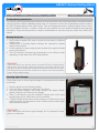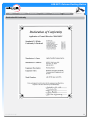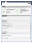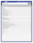
1
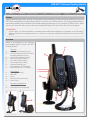
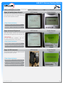
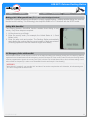
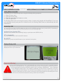
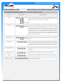
ASE-9575 Extreme Docking Station
Safety
Installation
General Use
F.A.Q.
Troubleshooting
Warranty
Appendix
Contacts
For additional information about this Product warranty, please contact your Service Provider or Point-ofSale. For additional information about ASE products and services, please contact ASE as follows:
Mail: Applied Satellite Engineering, Inc.
16559 North 92nd Street, Suite 101
Scottsdale, Arizona 85260 USA
Telephone:480.443.1424
Facsimile:
480.452.0971
Website:
www.ase-corp.com
E-mail:[email protected]
International Branch
Mail:
Applied Satellite Engineering, Intl.
46 An Leac Lian
Barna, County Galway
Ireland
Telephone: 353 85 761 5506
Facsimile:
353 91 591 702
Table of Contents
Contacts1
Table of Contents
1
Preface2
Overview2
Safety Information
3
Common Wire Connections
6
Attach External Antennas
6
Attach & Lock Power Input Jack
6
Attach Mini USB (optional except for data connectivity)
6
Optional Wire Connections
7
Attach Corded Privacy Handset (Included with Mounting Accessory Kit)
7
Attach RJ-11 Analog Phone / PABX Interface (9575P Only)
7
Docking your 9575 Handset
8
Open Protective Cover / Unlock Antenna Clasp
8
Dock Handset / Lock Antenna Clasp
8
General Use
9
Power On Messages
9
Stage 1) Dock Power On & POST
9
Stage 2) Handset Power & POST 9
Stage 3) Satellite Network Search 10
Stage 4) Network Registered
10
Stage 5) 9575 Undocked
10
Making a Call - What you will hear (RJ-11 and corded intelligent handset)
11
Calling With SmartDial
11
911 Emergency Calls with SmartDial
11
Calling Without SmartDial
12
Answering a Call
12
Displays During a Call
12
Accessing Docking Station Settings (RJ-11 and corded intelligent handset)
13
Accessing Star8 Diagnostics (RJ-11 and corded intelligent handset)
14
Frequently Asked Questions
15
Troubleshooting Introduction
16
Booting the System
16
Checking Signal Strength
16
Antenna Cable Runs
17
Installation and Startup Troubleshooting
17
ASE Limited Warranty
18
Declaration Of Conformity
20
V1.0 [2012-7-18]
1
ASE-9575 Extreme Docking Station
Safety
Installation
General Use
F.A.Q.
Troubleshooting
Warranty
Appendix
Preface
Applied Satellite Engineering, a leader in the satellite communications, provides a unique solution for using your
9575 Iridium satellite phone indoors and outdoors. Just dock your Iridium phone in our Docking Station and you
can access satellite communications with standard analog phone sets or your company’s PABX system. When
you need to leave the office, just un-dock your handset and take it with you. Never be out of touch again!
QUESTIONS
If at any time, you have questions or concerns about either the installation or operation of your Docking
Station, please visit www.ase-corp.com or contact us using the information located on the cover of this
manual.
Overview
Below is a breakdown of the features
and Interface points of your new 9575
Docking Station.
Features
A........Iridium 9575 Handset (not incl.)
B........Universal Mounting Kit with Corded
Intelligent Handset (optional)
C........UpLink LED Indicator (Green)
D........Voice LED Indicator (Blue)
E........Data LED Indicator (Blue)
F........Error LED Indicator (Red)
G........Handset Restraint Lock
I........External MIC or PTT Handset
J........External SPKR or PTT Handset
Connections
K........External Antenna(s)
L........Mini USB
M........RJ-11
N........RJ-45 (behind corded handset)
O........Power Input
A
G
L
I, J
B
Alternate Configurations
P........Push-To-Talk Handset
Q.......Full-Duplex Mic and Speaker
P
Q
N
V1.0 [2012-7-18]
K
M
O
C
D
E
F
2
ASE-9575 Extreme Docking Station
Safety
Installation
General Use
F.A.Q.
Troubleshooting
Warranty
Appendix
PRECAUTIONS:
Please read and understand this User’s Manual before installing your Docking Station. Careless or incorrect
installation can degrade performance, damage both new and existing equipment, and incur unexpected
network airtime charges.
Safety Information
1. FAA Regulations
ASE products are not FAA-approved and are not intended for aircraft use.
2. Exposure to Radio Frequency Signals
Your Iridium-designed satellite unit is a low power radio transmitter and receiver. When it is On, it receives
and sends out radio frequency (RF) signals.
International agencies have set standards and recommendations for the protection of public exposure to RF
electromagnetic energy:
• International Commission on Non-Ionizing Radiation Protection (ICNIRP) 1996
• Verband Deutscher Elektrotechniker (VDE) DIN-0848
• United States Federal Commission, Radio Frequency Exposure Guidelines (1996)
• National Radiological Protection Board of the United Kingdom, GS 11, 1988
• American National Standards Institute (ANSI) IEEE C95, 1-1992
• National Council on Radiation Protection and Measurements (NCRP) Report 86
• Department of Health and Welfare Canada, Safety Code 6
These standards are based on extensive scientific review. For example, over 120 scientists, engineers,
and physicians from universities, government health agencies, and industry reviewed the available body of
research to develop the updated ANSI standard.
The design of your phone complies with these standards when used as described under “Unit Operation.”
3. Antenna Care
Use only the antenna supplied by your service provider or an approved replacement antenna. Unauthorized
antennas, modifications, or attachments could degrade performance or damage the phone and may violate
local agency regulations.
4. Unit Operation
Do not operate the unit when a person is within 4 inches (10 centimeters) of the antenna. A person or object
within 4 inches (10 centimeters) of the antenna could impair call quality and may cause the unit to operate
at a higher power level than necessary and expose that person to RF energy in excess of that established
by the FCC RF Exposure Guidelines.
5. Driving
Check the laws and regulations on the use of wireless telephones in the areas where you drive. Always obey
them. Observe the following guidelines when using your phone while driving:
• Give full attention to driving; driving safely is your first responsibility.
• Use hands-free phone operation, if available.
• Pull off the road and park before making or answering a call if driving conditions so require.
V1.0 [2012-7-18]
3
ASE-9575 Extreme Docking Station
Safety
Installation
General Use
F.A.Q.
Troubleshooting
Warranty
Appendix
Safety Information (Continued)
6. Electronic Devices
Most modern electronic equipment is shielded from RF signals. However, certain equipment may not be
shielded against RF signals from your Iridium-designed satellite unit.
7. Pacemakers
The Health Industry Manufacturers Association recommends that a minimum separation of 6 inches be
maintained between a wireless phone’s antenna and a pacemaker to avoid potential interference with the
pacemaker. These recommendations are consistent with the independent research by and recommendations
of Wireless Technology Research.
PERSONS WITH PACEMAKERS
•
•
Should ALWAYS keep the Iridium-designed satellite unit more than six inches from their pacemaker
when the unit is turned On.
Should turn the unit Off immediately if you have any reason to suspect that interference is taking place.
8. Other Medical Devices
If you use any other personal medical device, consult the manufacturer of your device to determine if it is
adequately shielded from external RF energy. Your physician may be able to assist you in obtaining this
information.
Turn your unit Off in health care facilities when any regulations posted in these areas instruct you to do so.
Hospitals or health care facilities may be using equipment that could be sensitive to external RF energy.
9. Vehicles
RF signals may affect improperly installed or inadequately shielded electronic systems in motor vehicles.
Check with the manufacturer or its representative regarding your vehicle. You should also consult the
manufacturer of any equipment that has been added to your vehicle.
10. Posted Facilities
Turn your unit Off in any facilities where posted notices so require.
11. Blasting Areas
To avoid interfering with blasting operations, turn your unit Off when in a “blasting area” or in areas posted
“Turn off two-way radio.” Obey all signs and instructions.
12. Potentially Explosive Atmospheres
Turn your unit Off and disconnect the power supply when you are in any area with a potentially explosive
atmosphere. Obey all signs and instructions. Sparks from your battery or power source in such areas could
cause an explosion or fire resulting in bodily injury or even death.
Areas with a potentially explosive atmosphere are not always clearly marked. They include, but are not
limited to: fueling areas such as gasoline stations; below deck on boats; fuel or chemical transfer or storage
facilities; areas where fuel odors are present (for example, if a gas/propane leak occurs in a car or home);
areas where the air contains chemicals or particles, such as grain, dust, or metal powders; and any other
area where you normally would be advised to turn off your vehicle engine.
V1.0 [2012-7-18]
4
ASE-9575 Extreme Docking Station
Safety
Installation
General Use
F.A.Q.
Troubleshooting
Warranty
Appendix
Safety Information (Continued)
13. For Vehicles Equipped With Airbags
An air bag inflates with great force. Do NOT place objects, including both installed or portable wireless
equipment, in the area over the air bag or in the air bag deployment area. If in-vehicle wireless equipment
is improperly installed and the air bag inflates, serious injury could result.
14. Important Notes for PABX System Users
If using the Docking Station with a PABX system, the following precautions must be followed to prevent
damage to your unit.
The Docking Station emulates a standard land-line wall jack and generates the required operating and
ringing voltages. Connect to a PABX as either a central office (CO) or trunk line. Never connect the Docking
Station to a PABX as an extension or damage to the PABX or Docking Station may result.
V1.0 [2012-7-18]
5
ASE-9575 Extreme Docking Station
Safety
Installation
General Use
F.A.Q.
Troubleshooting
Warranty
Appendix
Common Wire Connections
You may not need to make every accessory connection that you see outlined on the following pages. However,
the steps shown on this page are generally the most common and should be read carefully.
IMPORTANT:
If you are in doubt about the mounting options or the connectivity at any stage of this installation, please contact an
ASE representative for assistance. They will be able to guide you through your specific installation options more clearly.
Attach External Antennas
The 9575 Dock accepts a male TNC for
Iridium and a male SMA for GPS.
IMPORTANT:
Do not exceed cable lengths outlined in
the troubleshooting section of this manual.
Keep cable splices to a minimum.
Attach & Lock Power Input Jack
Align the pin of the cord with the receptacle
and press the plug firmly in place. Next twist
the collar to “lock” the cord to the Docking
Station.
IMPORTANT:
The lock collar on this cable should only be
tightened “finger-tight.” Do not use pliers
as this will overtightened the cable and
potential damage the connector housing.
Attach Mini USB (optional except for data connectivity)
Align the Mini USB plug by positioning the graphic icon toward yourself, and gently
press it into the receptacle. The plug should give you a tactile “click” once it is fully
inserted.
V1.0 [2012-7-18]
6
ASE-9575 Extreme Docking Station
Safety
Installation
General Use
F.A.Q.
Troubleshooting
Warranty
Appendix
Optional Wire Connections
The steps on this page may not be applicable to every installation, and should be considered optional.
IMPORTANT:
If you are in doubt about the mounting options or the connectivity at any stage of this installation, please contact an
ASE representative for assistance. They will be able to guide you through your specific installation options more clearly.
Attach Corded Privacy Handset (Included with Mounting Accessory Kit)
Connect your Corded Intelligent Handset to
the RJ-45 jack as shown. The plug should
be pressed into the socket until an audible
‘click’ is heard; this indicates the plug is fully
seated and locked in position.
IMPORTANT:
Although this port uses a common
RJ-45 connector, it will NOT support a
connection to anything other than an
Corded Intelligent Handset. Additionally,
only one handset is supported.
Attach RJ-11 Analog Phone / PABX Interface (9575P Only)
Connect your telephone line to the RJ-11
jack as shown. The plug should be pressed
into the socket until an audible ‘click’ is
heard; this indicates the plug is fully seated
and locked in position.
TO REMOVE:
Use your finger to squeeze the small
plastic tab on the plug; this will “unlock”
the plug thus allowing for its removal.
V1.0 [2012-7-18]
7
ASE-9575 Extreme Docking Station
Safety
Installation
General Use
F.A.Q.
Troubleshooting
Warranty
Appendix
Docking your 9575 Handset
The docking process is described below. Connections to the 9575 handset are made at two separate locations
and the Docking Station is designed to self-align all of its electrical connections. However care should be taken
to avoid using excess force when docking.
Open Protective Cover / Unlock Antenna Clasp
The 9575 Dock is fully compatible with the
9575 Extreme Handset’s protective covers.
Simply open the protective cover on the heel
of the handset and slide into the Dock with it
open to accept the mating cable. Then slide
the mating cable through the retaining slot at
the bottom of the Dock until it fully engages
and locks with the handset. Alternatively,
the mating cable can be connected before
Docking and then seated into the Dock from
the top.
Dock Handset / Lock Antenna Clasp
After connecting the mating cable to the
handset as described above, lock the handset
securely into the Dock with the handset lock.
To remove the 9575 handset from the Dock,
open the handset lock and lift the handset
straight up until it clears the retaining slot at
the bottom of the Dock. Disconnect the mating
cable by pressing on the connector’s locking
clips.
V1.0 [2012-7-18]
8
ASE-9575 Extreme Docking Station
Safety
Installation
General Use
F.A.Q.
Troubleshooting
Warranty
Appendix
General Use
Refer to the instructions provided with your Iridium antenna to ensure proper placement. Clear line of sight to
the Iridium satellites is fundamental to satellite phone connectivity. Be sure the antenna will reach your desired
installation point inside your building without exceeding maximum length guidelines. The Docking Station must
be installed in a dry, climate-controlled location.
Power On Messages
The 9575 Docking Station goes through
several stages of system-checks and
network registrations prior to being ready for
use. Throughout these steps, you can follow
the system status by monitoring the 9575
Handset, the Corded Intelligent Handset,
the Docking Station Icon Indicators, and
even the audio output from a connected
telephone.
FYI:
POST = “Power On Self Test”
Stage 1) Dock Power On & POST
Start-Up Stage
Description
1
Dock Power / POST
Dock Power-On / Internal Systems Check
2
Handset Power / POST
Handset Power-On / Internal Systems Check
3
Satellite Search
Handset searches for Iridium satellite network
4
Network Registered
Handset is Ready for Use
9575 Handset
Corded Handset
9575 Handset
Corded Handset
When first powered-on (or reset) the Docking
Station will initiate a series of system checks
which generally take about 15 seconds to
complete.
Other Status Indicators:
RJ-11 Audio: Short-Long (repeat)...
Dock LEDs: Will “scroll” through each icon
Stage 2) Handset Power & POST
The intelligent handset powers up and
initializes immediately when plugged in and
displays system status.
Other Status Indicators:
RJ-11 Audio: Short-Long (repeat)...
Dock LEDs: Error icon (red) will blink
V1.0 [2012-7-18]
9
ASE-9575 Extreme Docking Station
Safety
Installation
General Use
Stage 3) Satellite Network Search
F.A.Q.
Troubleshooting
Warranty
Appendix
9575 Handset
Corded Handset
9575 Handset
Corded Handset
9575 Handset
Corded Handset
Once the 9575 Handset has completed its
own start-up process, it will begin searching
for the Iridium satellite network.
Other Status Indicators:
RJ-11 Audio: Short-Long (repeat)...
Dock LEDs: Satellite icon will blink
Stage 4) Network Registered
Once the satellite network has been found,
the handset will Register and be ready for use.
IMPORTANT:
If you encounter problems, see
troubleshooting section of this manual.
the
Other Status Indicators:
Handset & RJ-11 Audio: Dailtone...
Dock LEDs: Satellite icon (green) stays lit
Stage 5) 9575 Undocked
The Docking Station indicates when the 9575
handset has been removed.
Other Status Indicators:
9575 Removed
Handset Audio: none (display msg only)
RJ-11 Audio: [Long]-[Short] (repeat...)
Dock LEDs: Error icon (red) stays lit
V1.0 [2012-7-18]
10
ASE-9575 Extreme Docking Station
Safety
Installation
General Use
F.A.Q.
Troubleshooting
Warranty
Appendix
Making a Call - What you will hear (RJ-11 and corded intelligent handset)
SmartDial is special technology developed to simplify satellite dialing - making satellite dialing the same as
familiar land-line dialing. This technology also simplifies PABX to RJ-11 interface with the 9575P model.
Calling With SmartDial
The Docking Station’s SmartDial function enables direct dialing to any
country. Only three steps are required:
1. Lift the phone to go off-hook.
2. Enter the country code. (For example, the United States is 1, Great
Britain is 44.)
3. Enter the area code and number. The Docking Station automatically
starts dialing the number after the correct number of digits are entered.
(Pressing # places the call with whatever digits were dialed)
+1_
United States
911 Emergency Calls with SmartDial
With SmartDial turned on and USA 911 turned on in the Options settings (see settings), dialing 911 from Docking Stations
registered in the United States will call emergency services. Because 91 is the country code for India, the Docking Station
must be programmed to ignore the country code if 911 is dialed. For United States users, this is the best setting, even if
calls to India are frequent (it is safer to use SmartDial Override and keep 911 functionality).
WARNING:
With ‘USA 911’ turned off, you must dial ‘911’ and then ‘#’ to send to complete the call. Otherwise, all calls starting with
‘91’ will be recognized as calls to India.
V1.0 [2012-7-18]
11
ASE-9575 Extreme Docking Station
Safety
Installation
General Use
F.A.Q.
Troubleshooting
Warranty
Appendix
Calling Without SmartDial
SmartDial turns off automatically when using the following dialing sequence:
1. Enter 0 0 (zero zero).
2. Enter the country code.
3. Enter the area code and telephone number.
4. Enter # to place call.
The Docking Station does not recognize country codes or number string lengths with SmartDial off. You must
enter all digits correctly and press # to initiate the call—the Docking Station does not automatically dial with
SmartDial off.
Answering a Call
An incoming call will ring the 9575 handset as well as an RJ-11/POTS connected phone (model 9575P). Depending on
the connected accessories, the call can be answered in one of the following ways:
Intelligent Privacy Handset (DPL)
Remove Privacy Handset from its latching hang-up cup and press the GREEN OK key.
PTT or Speaker/Mic
Press the GREEN key on the Docked 9575 handset.
RJ-11/POTS
Go off-hook or press the On/Off button on your connected 2-wire phone.
Displays During a Call
When you make an outgoing call, the handset
displays the time of your connection.
DPL Call In Progress
In Progress
0:37
Power Loss Warning!
If power to the Docking Station is lost or removed while on a voice or data call, there’s a possibility that the
9575 will NOT terminate the call – nor will the Docking Station be able to terminate the call when re-powered.
The Docking Station will blink the ERROR indicator and the message “SEARCHING…” will be displayed
on the intelligent handset when in this condition. Additionally, the 9575 will be unresponsive to any key
press including the On/Off button. The call MUST be terminated at the remote end to regain control of
the 9575. Alternatively, the 9575 may be removed from the Docking Station so the battery pack on the
9575 can be removed and reinserted, forcing a hard reset of the phone.
V1.0 [2012-7-18]
12
ASE-9575 Extreme Docking Station
Safety
General Use
Installation
F.A.Q.
Troubleshooting
Warranty
Appendix
Accessing Docking Station Settings (RJ-11 and corded intelligent handset)
OPTION
Volume
SEQUENCE
*
20
DESCRIPTION
1
2
3
4
5
Lowest
Press *20 and then press 1 through 5 to change the volume
level sent to the handset. Press 1 to adjust the volume to its
lowest level, and 5 to adjust it to its highest.
Highest
US 911
*
50
0
1
Disabled
Enabled
Press *500 to toggle USA 911 dialing off and *501 to toggle it
on. By default, the Docking Station is set to USA 911 On. We
strongly recommend leaving 911 dialing on if you are a United
States customer. Be sure to read the sections below discussing
emergency 911 calls. This setting partially overrides SmartDial
recognition of country codes and allows United States callers to
simply type 911 to access the emergency system. (If this setting
is off, then calls starting with “91” are recognized as dialing the
country code for India.)
Captain’s Sim
*
53
0
1
Disabled
Enabled
Press *530 for standard SIM card. Press *531 for Captain’s
SIM.
###
Press *7 to reach the Phone Book that resides in the SIM card,
then enter the three-digit QuickDial number for the entry you
wish to dial. Hang up to exit this menu. See the section below
“Managing Your Phone Book” to learn more about this option.
Phone Book
*
7
,
Firmware Version
*
9
9
1
Displays the Dock model and version numbers on Privacy
Handset
Serial Number
*
9
9
2
Displays the Dock Serial Number on Privacy Handset
IMEI
*
9
9
3
Displays the Serial Number of 9575 on the Privacy Handset
1
2
3
4
Restore Defaults
V1.0 [2012-7-18]
*
5
Restores default settings
13
ASE-9575 Extreme Docking Station
Safety
General Use
Installation
F.A.Q.
Troubleshooting
Warranty
Appendix
Accessing Star8 Diagnostics (RJ-11 and corded intelligent handset)
ASE’s Star8™ features can perform a signal strength assessment that accounts for cabling distance, connector
quality, and antenna placement. This evaluation may detect the presence of a structure or object that obstructs
the signal’s path to the satellite. These powerful diagnostic features can be performed during installation or
utilized as a part of scheduled maintenance to ensure that the system is working at peak performance.
OPTION
Signal Strength
Tests
SEQUENCE
*
80
0
1
2
DESCRIPTION
NOW
10
30
Reports Iridium signal strength on the corded handset display,
or as a series of audible beeps played on the RJ-11 handset.
The number of beeps (0 to 5) represents signal strength (none
to excellent)*.
Options
NOW: current signal strength
10: 10 minute average taken every minute**
30: 30 minute average taken every minute**
*zero, or no beeps indicates antenna not connected
**error tone given if not enough time has elapsed to compute
the average
Antenna Blockage
Tests
*
81
1
2
10
30
Reports potential Iridium antenna blockage displayed on the
corded handset, or as a series of audible beeps played on the
RJ-11 handset. The number of beeps (0 to 5) represents the
percentage of blockage (none to severe)*.
Options
10: percentage of bad signal strength over 10 minute period**
30: percentage of bad signal strength over 30 minute period**
*zero, or no beeps indicates no antenna blockage detected
**error tone given if not enough time has elapsed to compute
the percentage
V1.0 [2012-7-18]
14
ASE-9575 Extreme Docking Station
Safety
Installation
General Use
F.A.Q.
Troubleshooting
Warranty
Appendix
Frequently Asked Questions
QUESTION:
How do callers dial in order to reach
my Docking Station?
SOLUTION:
Your service provider will give you your Iridium phone number. Callers simply
dial 011 (to reach an international line), then your Iridium number (starting
with 8816). You might want to point out that your Iridium number does not
follow standard United States format. There are 12 digits in your Iridium
number.
QUESTION:
Can I use an answering machine with
the Docking Station?
SOLUTION:
Yes, answering machines operate correctly with the Docking Station. Just
attach the answering machine to the RJ-11 jack on the Docking Station
unit as if you were plugging into the wall jack; then connect the rest of your
equipment as described in the answering machine user’s guide.
QUESTION:
Can I use a fax machine with the
Docking Station?
SOLUTION:
No, fax machines will not function with the Docking Station due to
shortcomings in satellite technology.
V1.0 [2012-7-18]
15
ASE-9575 Extreme Docking Station
Safety
Installation
General Use
F.A.Q.
Troubleshooting
Warranty
Appendix
Troubleshooting Introduction
The following are troubleshooting techniques to help resolve the most common problems encountered when
using this product. Before attempting these tests, it’s important to review the ‘Preparations’ section found in
the ‘9575 Docking Station Quick Start Guide’. This and related documents; ‘Docking Station User’s Guide’
and ‘Fixed Station Terminal – Installer’s Guide’ are also available for more detailed installation and operating
information. These documents can be viewed or downloaded at: www.ase-corp.com under the ‘Product Info’
section.
Booting the System
1. Verify Iridium handset PIN code is turned off and there is sufficient
battery power.
2. Install phone in Docking Station following the instructions outlined
earlier in this manual.
3. Lock the handset in place using the latch located in the upper left hand
corner of the device.
4. The 9575 handset will power-up automatically or turn off and re-start
depending on the state of the 9575 when docked.
IMPORTANT:
If the Dock cannot sync with the phone, the status LED (A) will keep blinking
and the Dock will eventually re-boot itself and try to sync again. When the top
LED goes on solid, the phone will remain on and the Dock is ready for use. If the
LED keeps blinking and the Dock continues to re-boot, most common problem
is poor Iridium signal strength.
A
Checking Signal Strength
Follow these steps to check signal strength to the handset while installed
in the Dock:
1. Remove power from the Docking Station.
2. Turn only Iridium handset On while still in the Dock.
3. Verify the phone registers with Iridium network and signal strength
shows at least 4 out of 5 bars on the display.
4. Place a call directly using the handset’s keypad and verify signal
strength stays at 4 to 5 bars once call is connected.
5. If signal strength drops below 4 bars during any of these tests, check
antenna location for obstructions and/or confirm antenna cable length
has not been exceeded.
IMPORTANT:
Each cable splice will reduce signal strength. So it’s important to keep
splices to a minimum.
V1.0 [2012-7-18]
16
ASE-9575 Extreme Docking Station
Safety
Installation
General Use
F.A.Q.
Troubleshooting
Warranty
Appendix
Antenna Cable Runs
This table gives maximum cable runs for common LMR cable types. These
maximum lengths are based on Iridium’s specified max signal loss of 3 dB
from antenna to handset, and assumes there are no splices or couplers in
the cable run.
Helpful Tip: Each connector/splice will reduce signal strength by
approximately 0.5 dB.
Type
Max Length
LMR-195
15.0 ft
4.57 m
LMR-240
22.1 ft
6.74 m
LMR-400
42.6 ft
12.98 m
LMR-600
65.7 ft
20.03 m
LMR-900
97.1 ft
29.60 m
LMR-1200
129.0 ft
39.32 m
AVA5-50
148.4 ft
45.23 m
Installation and Startup Troubleshooting
SYMPTOM:
Satellite icon (green) LED never
stays on solid and continues to blink,
system keeps re-booting
SYMPTOM:
Busy Signal present on RJ-11 analog
phone
SYMPTOM:
Signal strength drops when a call is
placed
CAUSE:
Docking Station is unable to synchronize with the handset and Iridium
network.
RESOLUTION:
Check Dock mating cable connection, verify docked handset has the PIN
code turned Off, check antenna signal strength.
CAUSE:
Another symptom that the Dock cannot sync with the Iridium network.
RESOLUTION:
Verify docked handset has the PIN code turned Off, check antenna signal
strength.
CAUSE:
Check antenna location for obstructions, a 360 degree clear view of the sky
is required for proper operation. Antenna cable length exceeded or there are
too many splices in cable run.
RESOLUTION:
Re-position antenna away from obstructions, verify cable length has not
been exceeded, eliminate unnecessary cable splices.
V1.0 [2012-7-18]
17
ASE-9575 Extreme Docking Station
Safety
Installation
General Use
F.A.Q.
Troubleshooting
Warranty
Appendix
ASE Limited Warranty
1. Coverage and Duration
Applied Satellite Engineering, Inc. (ASE) warrants that its new satellite subscriber radiotelephone products
and accessories (the “Product”) shall be free from defects in materials and workmanship for a period of
twenty-four (24) months from the date such Product is delivered to the first end-user purchaser or first lessee
(the “Purchaser”), or the date such Products are first placed into satellite subscriber service, whichever
occurs earliest. ASE, at its option, shall at no charge to Purchaser, either repair or replace the Product,
or refund the purchase price of a Product that does not conform to this warranty, provided the Product is
returned in accordance with the instructions set out below and within the warranty period. These remedies
are Purchaser’s exclusive remedies under this warranty. Repair may include the replacement of parts or
boards with functionally equivalent reconditioned or new parts or boards. A Product that has been repaired
or replaced is warranted for the balance of the original warranty period. A Product for which a replacement
has been provided shall become ASE’s property.
This warranty is made by ASE to the Purchaser of the Products only, and it is not assignable or transferable
by the Purchaser. This is ASE’s sole and complete warranty for the Products. ASE assumes no obligation or
liability for additions or modifications to this warranty unless made in writing and signed by an officer of ASE.
ASE does not warrant any installation, maintenance, or service of the Products not performed by ASE.
This product is covered by a U.S.A. warranty. If the Product has been sold outside of the U.S.A., ASE will
honor the U.S.A. warranty terms and conditions only. Outside of the U.S.A., any different warranty terms,
liabilities, and/or legal requirements of the country in which the Product is sold are specifically disclaimed
by ASE.
2. Conditions Not Covered By This Warranty
a) Products that are integrated, installed, maintained, or serviced in any manner other than in accordance
with the ASE user documentation furnished with or applicable to the Product.
b) Product damage caused by the use of ancillary equipment not furnished by ASE, including accessories
and peripherals.
c) Problems where the Product is used in a combination with ancillary equipment not furnished by ASE and
it is determined by ASE there is no fault with the Product.
d) Ancillary equipment not furnished by ASE that is attached to or used in connection with the Products is not
the responsibility of ASE, and all such equipment is expressly excluded from this warranty. Furthermore, ASE
does not warrant the integrated operation of the combination of the Products with any ancillary equipment
not furnished by ASE.
e) Defects or damage resulting from: use of the Product in any manner not normal or customary; misuse,
accident, or neglect, including but not limited to dropping the Product onto hard surfaces, immersion in or
exposure to water, rain or extreme humidity, immersion in or exposure to sand, dirt, or other particulates,
exposure to extreme heat, spills of food or liquid; improper testing, operation, maintenance, installation,
adjustment; or any alteration or modification of any kind.
f) Batteries manufactured by ASE and sold with Products whose capacity exceeds 80% of rated capacity
are not covered. Batteries whose capacity falls below 80% of rated capacity, or that develop leakage, shall
be considered non-conforming. This warranty is voided for batteries if: i) such batteries are charged by other
than the ASE-approved battery charger specified for charging such batteries; ii) any seals on such batteries
are broken or show evidence of tampering; iii) such batteries are used in equipment other than the Product
for which they are specified; or iv) such batteries are charged and stored at temperatures greater than 60
degrees Celsius.
g) Breakage or damage to antennas, or scratches or other damage to plastic surfaces or other externally
exposed parts caused by Purchaser’s use.
V1.0 [2012-7-18]
18
ASE-9575 Extreme Docking Station
Safety
Installation
General Use
F.A.Q.
Troubleshooting
Warranty
Appendix
ASE Limited Warranty (Continued)
h) Products disassembled or repaired in such a manner as to adversely affect performance or prevent
adequate inspection and testing to verify any warranty claim.
i) Products on which serial numbers or date tags have been removed, altered, or obliterated.
j) Coil cords that are stretched or on which the modular tab is broken; leather cases, which are covered
under separate manufacturer’s warranties.
k) Products rented on a month-to-month basis.
l) Normal wear and tear.
3. Obtaining Warranty Service
For warranty questions, repairs, or for the return of Product, please call your Service Provider or Point-of-Sale,
not ASE. Equipment needing service should be returned to your Service Provider or Point-of-Sale, not ASE.
SERVICE WORK PERFORMED BY SERVICE CENTERS NOT AUTHORIZED BY ASE TO PERFORM SUCH
WORK WILL VOID THIS WARRANTY.
All products shipped to ASE’s authorized Warranty Service Center must be shipped with freight and insurance
prepaid. Purchaser must include with the Product a bill of sale, a lease, or some other comparable proof of
purchase, the name and location of the installation facility, if any, and most importantly, the Purchaser’s name,
address, and telephone number and a written description of the problem. Product that is repaired or replaced
under this warranty shall be returned to Purchaser at ASE’s expense for the freight and insurance, and at
Purchaser’s expense for any applicable duties or other charges. If additional information is needed, please
contact ASE at the address and phone number listed in this document.
4. General Provisions
THIS WARRANTY IS GIVEN IN LIEU OF ALL OTHER WARRANTIES EXPRESS OR IMPLIED, INCLUDING
BUT NOT LIMITED TO THE IMPLIED WARRANTIES OF MERCHANTABILITY AND FITNESS FOR A
PARTICULAR PURPOSE. FURTHER, THIS WARRANTY COVERS THE PRODUCTS ONLY, AND NO
WARRANTY IS MADE AS TO COVERAGE, AVAILABILITY, OR GRADE OF SERVICE PROVIDED BY ASE
SEPARATELY FOR ASE SATELLITE SERVICES. IN NO EVENT SHALL ASE BE LIABLE FOR DAMAGES
IN EXCESS OF THE PURCHASE PRICE OF THE PRODUCT IN QUESTION, OR FOR ANY LOSS OF USE,
LOSS OF TIME, INCONVENIENCE, COMMERCIAL LOSS, LOST PROFITS OR SAVINGS OR OTHER
INCIDENTAL, SPECIAL, OR CONSEQUENTIAL DAMAGES ARISING OUT OF THE USE OR INABILITY TO
USE SUCH PRODUCT, TO THE FULL EXTENT SUCH MAY BE DISCLAIMED BY LAW.
5. State Law and Other Jurisdiction Rights; Software Copyrights
Some states and other jurisdictions do not allow the exclusion or limitation of incidental or consequential
damages, or limitation on how long an implied warranty lasts, so the above limitations or exclusions may not
apply to Purchaser.
This warranty gives Purchaser specific legal rights, and Purchaser may also have other rights that vary from
jurisdiction to jurisdiction.
Laws in the United States and other countries preserve for ASE certain exclusive rights for copyrighted Product
software such as the exclusive rights to reproduce in copies and distribute copies of such Product software.
Product software may be copied into, used in, and redistributed with only the Product associated with such
Product software. No other use, including without limitation disassembly, of such Product software or exercise
of exclusive rights in such Product software is permitted.
V1.0 [2012-7-18]
19
ASE-9575 Extreme Docking Station
Safety
Installation
General Use
F.A.Q.
Troubleshooting
Warranty
Appendix
Declaration Of Conformity
V1.0 [2012-7-18]
20