1
Allen Datagraph Systems
i-TECH AXXIS SR Manual
Manual Date February 2011
Axxis user manual for build 12-R or later software
Copyright 2011 – Allen Datagraph Systems Inc – All Rights reserved
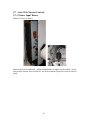
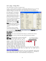
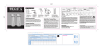
communication connector locations:
1
Table of Contents
1 Warranty......................................................................................................................... 5
2 Service Policy...................................................................................................................5
3 Technical Support...........................................................................................................6
4 Setting Up Your i-TECH AXXIS SR System...............................................................7
4.1 Installation of SR....................................................................................................... 7
4.1.1 Setup on Table.................................................................................................... 7
4.1.2 Installing Printer into SR....................................................................................7
4.1.3 Power .................................................................................................................7
4.1.4 Plugging-in Printer and SR System....................................................................7
4.1.5 Installation Order...............................................................................................8
4.1.5.1 Do not plug in devices................................................................................. 9
4.1.5.2 Install Illustrator...........................................................................................9
4.1.5.3 Insert CD......................................................................................................9
4.1.5.4 Select Epson b-500 Printer Driver from Web Page...................................10
4.1.5.5 Network Printer Driver Instructions.......................................................... 14
4.1.5.6 Setting Printer Driver Properties................................................................17
4.1.5.7 Select Wasatch from Web Page.................................................................18
4.1.5.8 Select Inkscape and Color Profiles from Web Page..................................21
4.1.5.9 Select Cutter Driver................................................................................... 21
4.1.5.10 Install Port Redirector Printer Driver.......................................................21
4.1.5.11 Configuration of Wasatch Hot Folder......................................................27
4.1.5.12 Setting Up the B500 in Wasatch..............................................................28
4.1.6 Software Updates..............................................................................................29
5 Operation of the i-TECH AXXIS SR System............................................................30
5.1 Setting Up Your Label Job...................................................................................... 30
5.2 Explanation of SmartMarkTM.................................................................................30
5.3 Types of SmartMarkTM Scanning.......................................................................... 31
5.4 Designing Labels..................................................................................................... 32
5.4.1 Planning Label................................................................................................. 32
5.4.2 Using Inkscape................................................................................................. 34
5.4.3 Using Adobe Illustrator....................................................................................36
5.5 Webbing the SR....................................................................................................... 38
5.6 Printing and Cutting............................................................................................41
5.6.1 Print and Cut Interface.....................................................................................41
5.6.1.1 Print and Cut from Inkscape......................................................................... 41
5.6.1.2 Print and Cut from Illustrator....................................................................... 41
5.6.2 Printing and Cut...............................................................................................41
5.6.3 Collate.............................................................................................................. 43
5.6.4 Variable Data................................................................................................... 45
5.7 Axxis Web Tension Controls...................................................................................49
2
5.7.1 Printer Input Dancer..............................................................................................49
5.7.2 Print Dancer Tension............................................................................................ 50
5.7.3 Laminate Tension..................................................................................................50
5.8 I-Tech Axxis SR Remote Panel and LCD Panel..................................................... 51
5.8.1 i-TECH Print Cut remote panel.................................................................... 51
5.8.2 Action Menu................................................................................................. 51
5.8.2.1 Save / Restore Calibration..................................................................... 51
5.8.2.2 Load / Save Settings from Cutter to File, ............................................. 51
5.8.3 Setup > Main Menu...................................................................................... 51
5.8.3.1 State Tab................................................................................................ 52
5.8.3.2 Knife Settings Tab................................................................................. 52
5.8.3.3 Rubber Tab.............................................................................................53
5.8.4 Setup > Line Sensor......................................................................................53
5.8.4.1 Line Sensor Tab .................................................................................. 53
5.8.4.1.1 Skew Tab ........................................................................................... 54
5.8.4.1.2 Scale Tab ..........................................................................................55
5.8.5 Setup -> Settings Menu.................................................................................56
5.8.6 Setup -> Options Menu.................................................................................58
5.8.7 Joystick......................................................................................................... 58
5.8.8 Front panel of i-TECH AXXIS Finisher.......................................................59
5.8.8.1 Mandrel Switches and Controls.................................................................63
6 Maintenance & Consumables......................................................................................63
6.1 B500 Printer (refer to Epson Manual)..................................................................... 63
6.1.1 Substrates......................................................................................................... 63
6.2 i-TECH AXXIS Finisher......................................................................................... 63
6.2.1 Changing a blade............................................................................................. 63
6.2.2 Changing a cut strip......................................................................................... 64
6.2.3 Cleaning........................................................................................................... 65
6.2.4 Pinch Wheel Maintenance................................................................................65
6.2.5 Mechanical Adjustments...................................................................................66
6.3 Troubleshooting i-TECH AXXIS Finisher..............................................................67
A Appendix A – i-TECH remote panel Advanced Options....................................... 72
A.1 Enable Advanced Options.....................................................................................72
A.2 Action Menu......................................................................................................... 72
A.2.4 Send HPGL File.............................................................................................72
A.2.5 Cancel, Continue, Pause................................................................................72
A.2.6 Open Com Port ............................................................................................. 72
A.2.7 Close Com Port..............................................................................................72
A.2.8 Upload Firmware...........................................................................................72
A.2.8.1 Firmware Installation Instructions:......................................................... 73
A.2.9 Save to EEROM and Restore from EEROM.................................................. 73
A.3 Setup Menu........................................................................................................... 73
A.3.4 Main Menu..................................................................................................... 73
A.3.5 Setup -> Line Sensor Skew tab...................................................................... 74
A.3.6 Setup -> Line Sensor Scale tab......................................................................75
3
A.3.7 Setup -> Settings............................................................................................ 75
A.3.8 Setup -> Options............................................................................................ 75
A.3.9 Setup → Dynamic Force ...............................................................................76
A.4 Diagnostics............................................................................................................76
A.4.4 How to run Diagnostics................................................................................. 77
A.4.4.1 From Front Panel.................................................................................... 77
A.4.4.2 From Remote Panel.................................................................................77
A.4.5 Setup Diagnostics...........................................................................................77
A.4.5.1 Setup/Operation Analog Accumulator Sensors...................................... 77
A.4.5.2 Diagnostic 40 Set Accumulator Length..................................................77
A.4.5.3 Diagnostic 55 Set Accumulator Type..................................................... 78
A.4.5.4 Diagnostic 45 Set Stepper Speed............................................................78
A.4.5.5 Diagnostic 44 Map Accumulator Position..............................................78
A.4.5.6 Calibrate 07.............................................................................................79
A.4.5.7 Calibrate to Printer..................................................................................79
A.4.5.8 Calibration Square Output...................................................................... 79
A.4.5.9 Default Calibration 08.............................................................................79
A.4.5.10 FO Output............................................................................................. 79
A.4.5.11 Smart Mark Setup................................................................................. 79
A.4.5.12 Sensor Offset.........................................................................................79
A.4.6 Customer Diagnostics....................................................................................81
A.4.6.1 Set Model Number 03.............................................................................81
A.4.6.2 LAN address IP assignments 04............................................................. 81
A.4.6.3 Button Diagnostic 31 ............................................................................. 82
A.4.6.4 Confidence Test 02................................................................................. 82
A.4.6.5 Flag Monitor / Adjust 34.........................................................................82
A.4.6.6 Flag and Print Dancer Setup - Z Axis 58 ..............................................83
A.4.6.7 Label Mode 64 ...................................................................................... 83
A.4.6.8 LED and LCD display 29 .......................................................................83
A.4.6.9 Line Sensor 21 ....................................................................................... 83
A.4.6.10 Amplifier Status....................................................................................83
A.4.7 Manufacturing Diagnostics............................................................................83
A.4.7.1 Collect Motor Position............................................................................83
A.4.7.2 Default Gains 48..................................................................................... 84
A.4.7.3 Lift/Lower Continuous 37.......................................................................84
A.4.7.4 Lift/Lower Demand 38............................................................................84
A.4.7.5 Line Sensor Test......................................................................................84
A.4.7.6 Motor Position Plot.................................................................................84
A.4.7.7 Read Calibration Constants.....................................................................84
A.4.7.8 Spare Out.................................................................................................84
A.4.7.9 Tuning (Engineering)..............................................................................84
A.4.7.10 Write Plot Data to Excel....................................................................... 84
B Appendix B – Error Codes........................................................................................84
C Appendix C – Radio and Television Interference...................................................85
4
1 Warranty
ALLEN DATAGRAPH Digital Finishing Systems are warranted to be free of defects in
both materials and workmanship. Should any part of this equipment be defective, it will
be repaired or replaced, at the option of the manufacturer, at no charge for parts or factory
labor for a period of one (1) year from the date of installation. All warranty services are
performed at the Allen Datagraph factory. Replacement parts not installed at the factory
will be billed to the customer at regular prices and credit will be issued when the
defective parts are returned. The customer is responsible for freight on warranty parts and
repairs.
This warranty is void if:
The equipment has been damaged by negligence, accident or mishandling, or has not
been operated in accordance with the procedures described in the operating instructions;
or:
The equipment has been altered or repaired by other than an approved service station or
factory service center, or adaptations or accessories have been attached to the equipment
that shall have adversely affected the performance, safety, or reliability of the equipment.
NO OTHER WARRANTY, EXPRESSED OR IMPLIED, APPLIES to the
equipment. Allen Datagraph does not assume any responsibility for consequential
damages occasioned by the equipment, or inconvenience or interruption in operation.
In case of unsatisfactory operation, Allen Datagraph or its Dealer should be notified
immediately.
2 Service Policy
When making your decision as to which way to proceed with the repair of your ADSI
equipment, please bear in mind that troubleshooting of complex electronic equipment can
sometimes take multiple attempts to repair an issue. It is always best from a
manufacturer’s point of view to have the complete system in-house to insure that the
machine is in perfect working order when you receive it back from us. Please consider all
aspects before making your decision as to which option to utilize. We make every
attempt to minimize downtime for our customers, and sometimes the best way is to have
the machine in our facility.
WARRANTY SERVICE:
Option 1) ATTEMPT TO REPAIR OVER THE PHONE: We do not normally encourage
customers to repair ADSI equipment on their own. Sometimes, in the interest of minimizing
downtime, and under the guidance of ADSI service personnel, we will try and repair an issue
over the phone. This may require that you ship us parts from your machine as per the warranty
statement found in the front of your ADSI user’s manual, or for ADSI to ship parts to you for
installation.
NOTE: Any replacement parts shipped to you require that you ship the old parts back to ADSI
unless previously approved. Failure to do so will result in the parts being charged to you. All
returned parts require a Return Material Authorization Number (RMA), which must be
obtained from an ADSI representative prior to return shipment.
5
All phone-supported repairs are handled on a per-case basis, and at the discretion of ADSI
Service personnel.
Option 2) SERVICE AT OUR FACILITY: Ship the machine to ADSI for repair under
the terms of the written warranty statement found in the user’s manual. Parts and labor
are provided at no charge to the customer, but the customer is responsible for freight to
and from Allen Datagraph.
Option 3) ON-SITE SERVICE: ADSI will, on occasion, for the cost of all airfare and travel
expenses, send an ADSI technician to your facility to repair in-warranty equipment. Parts and
labor are provided at no cost to the customer. Bear in mind that on-site service is sometimes not
the most cost or time-effective way to resolve issues and may result in longer down time due to
scheduling of airfare, etc.
NON-WARRANTY SERVICE:
In most out of warranty repair scenarios, we require customers to send the machine to us for
repair. This is the best way to insure that the machine you get back will be fully functional upon
arrival at your facility.
In some cases we may determine that the problem is a simple one, such as a belt, and decide the
issue may be resolved without shipping the machine in. In this case, you can decide to repair the
machine yourself. This will require us to ship parts to you for installation. Parts will be charged at
retail pricing prior to shipping. Bear in mind that this method may ultimately increase downtime
and/or may take more than one attempt to resolve the issue. If the issue cannot be resolved in a
timely manner, the machine will be required to be shipped to ADSI for service.
NOTE:A credit card number is required at the time of shipment of any parts. In a warranty
situation, the card will not be charged with the exception of shipping charges, as long as parts
are returned to ADSI in a timely manner. Non-warranty parts are required to be paid in full
prior to shipment.
3 Technical Support
Up to 4 hours of calls in technical support is available at no charge during the warranty
period. Technical support is available during business hours based on Eastern Time
Monday thru Friday. Technical support outside the limits stated will be billed at current
rates.
For Technical support use the Allen Datagraph web site. Click on Tech Support, or call:
603-216-6344
There are many online documents available to help you to use the AXXIS at our
technical support page at http://www.allendatagraph.com. Then click on Technical
Support and Online Documents then click on Axxis link under orange Label Production
heading.
6
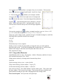
4 Setting Up Your i-TECH AXXIS SR System
The i-TECH AXXIS SR System consists of an Epson B500 Printer incorporated into the
ADSI SR laminator and cutter. The SR is designed for short run labels. The SR prints,
laminates and cuts dielines for labels.
Warning: Do not connect the Axxis SR or printer to the computer until told to do so by
the installation CD.
4.1 Installation of SR
4.1.1 Setup on Table
The i-Tech AXXIS SR is a tabletop label finishing device. Once removed from its crate,
place the unit on a table that can support 200+ Lbs (90 kg). You need at least 4 people to
move the SR from the shipping crate to a table.
4.1.2 Installing Printer into SR
Open the printer box, connect communication cables to printer and then set it in position
as shown in next section.
4.1.3 Power
WARNING: IF YOU RUN YOUR EQUIPMENT ON 220V
WITH INPUT MODULE SET FOR 110V IT WILL
DAMAGE YOUR EQUIPMENT.
4.1.4 Plugging-in Printer and SR System
Printer Power requirements
B-500DN printer 32 watts available only for following voltage models
Only available in one model 90-132 VAC 49.5-60.5
Hz
AC power for printer is converted from 220vac to 110vac by an internal transformer.
SR power requirement is 500 watts can be configured to operate from any of the
following power sources:
100-132 VAC / 47-63 Hz or 180-240 VAC / 47-63 Hz
Important Note: Use of a HIGH QUALITY surge protector or uninterruptible power
supply (500 sr + 32 b500 printer = 532 watts) is REQUIRED by Allen Datagraph
Systems. Failure to do so could affect your warranty coverage if a problem arises due to
improper power connection.
CAUTION: The power cord is a three-conductor cable that incorporates a safety (earth)
ground connection. For the machine to operate safely and correctly, the power cord must
be plugged into an outlet that has an earth ground contact. Never plug the power cord into
a two-prong outlet by using a 3=2 cord adapter.
CAUTION: Never allow roll or sheet goods to rub on the power cord because the
material can cut the cord causing an electrical fire hazard!
7
ALLEN DATAGRAPH products are factory preset for the power requirements of the
destination country. The machine's configuration is indicated on the power input module
as either 115V or 230V. To change the configuration:
a.
b.
c.
d.
Disconnect the AC power cord
from the fuse block on the power
input end panel.
Open the fuse block cover with a
small flat screwdriver.
Orient the fuse block so that the
desired voltage appears in the fuse
block cover. If you have 110v ac
use one 5 amp fuse. If you have
220v ac use two 2.5 amp fuses.
Close the fuse block cover and
verify that the desired voltage is
showing.
4.1.5 Installation Order
Software must be installed in the correct order or installation will fail.
Installation Summary: (Detailed instructions follow in subsequent sections.)
•
Do not plug in devices or communication cables until told to do so in the
installation instructions. If you do you will probably need to call tech support to
make your system work.
•
Install Illustrator artwork design package using the cd you purchased. Not
provided by ADSI.
•
Insert ADSI.CD. When you select a link from the web path displayed the
Explorer will ask you if you want to run the program twice. Click on run button
both times. A web page will appear select installations in following order:
•
If you don't have Adobe reader installed you can install it from the first link.
•
Next Open the SR Users Manual. Print out section 3.
•
Install Epson Printer Driver setup
•
Wait until software asks and then plug usb cable from computer to printer.
•
Run Wasatch installation setup.
•
Install Inkscape
•
Install Wasatch Color Profiles
•
Install Cutter Driver. When told to connect usb or Ethernet cable.
•
Install Remote Panel
•
Install Port Redirector printer driver
8
•
Setup hot folder server
4.1.5.1 Do not plug in devices
Note: Do not plug in devices or communication cables until told to in the
installation instructions.
If you plug in the cables before you are asked to you will have trouble getting drivers
loaded and will probably have to call technical support to get drivers installed.
4.1.5.2 Install Illustrator
If you are using Adobe Illustrator It must be installed before you start. Since this
program is not provided by ADSI. Follow installation instructions provided by Adobe.
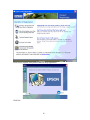
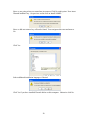
4.1.5.3 Insert CD
Insert the ADSI Driver CD that came with the SR. A web page will appear with links to
install software in yellow. Select the links and click on run when directed to by the
following installation instructions. If the web page does not appear use the start > My
Computer and right click on the CD drive and select Autorun or double click on the
srhome in the root directory of the CD.
9
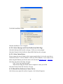
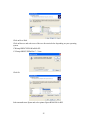
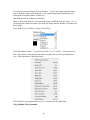
4.1.5.4 Select Epson b-500 Printer Driver from Web Page
Click on Easy Install
click on Local if you connected printer via usb and Network if you connected printer via
Ethernet.
'
10
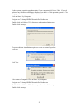
Click on Install.
Click on Agree to license.
11
Wait (skip to next section for network installation.)
Wait
Plug in usb cable from printer to computer
12
Register your software if desired.
Click Exit
Skip next section
13
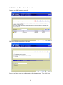
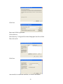
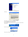
4.1.5.5 Network Printer Driver Instructions
Connect your b500 printer to network.
Select the b-500dn printer, then click next
If you do not have paper tray loaded uncheck the print test page.. Then click Next.
14
Select No Change in drop down and click next
Click Finish
Wait for driver installation to complete.
15
Click Next to register your print or cancel to skip registration.
Click Exit
16
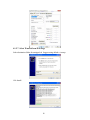
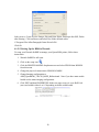
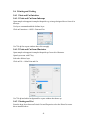
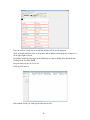
4.1.5.6 Setting Printer Driver Properties
Click on Start > control panel > printer and faxes or printers Right click on the b500dn
printer and select printing preferences.
Set Printing Preferences as follows:
17
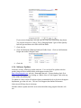
4.1.5.7 Select Wasatch from Web Page
Select destination folder for unzipped cd. Suggest using default c:\wtemp.
Cick Install.
18
There will be a long wait while the cd image is unpacked.
Check I have read... Click Accept to accept license agreement
Select installation language from drop down.
First select Install Hardware Key
19
Since we are going to have to restart later just answer Click No at this point. Now insert
Wasatch hardware key. On previous screen click on Install SoftRIP.
Since we did not restart a key will not be found. You can ignore this error and answer
No.
Click Yes.
Select additional installation languages if desired
Click Yes if you have installed Wasatch before on this computer. Otherwise click No.
20
Use default installation folder.
Wasatch installation is now complete.
4.1.5.8 Select Inkscape and Color Profiles from Web Page
Select the Inkscape link from the web page. Follow on screen prompts
Select the Wasatch Color Profiles for Epson B500 link from the web page
4.1.5.9 Select Cutter Driver
Do not connect the Axxis finisher to the computer until told to do so by the cutter driver.
Connection from PC to Axxis Finisher is either by USB or Ethernet. If you want to read
about using the Ethernet port for the cutter see the document Website Copy / CD Copy.
Select the cutter driver link from web page
Click Yes to auto install question
When asked during this install connect computer to cutter port of SR
Select the Remote Panel link from the web page
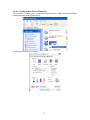
4.1.5.10Install Port Redirector Printer Driver
Left click on start, right click on My Computer , left click on Properties
21
On the system properties page determine if your computer is 64 bit or 32 bit. If you do
not have any indication on the page displayed you have a 32 bit operating system. Close
this page.
Click on Start / My Computer
Navigate to C:\Wtemp\SRIP67\Wasatch Port Redirector
Double click on 64 bit or 32 bit directory as determined in last step.
Double click on setup:
The port redirector installation requires a reboot or restart of spooler.
Click Ok
Click Yes
After restart of computer Click on Start / my computer
Navigate to C:\Wtemp\SRIP67\Wasatch Port Redirector
Double click on 64 bit or 32 bit directory as determined in last step.
Double click on setup:
22
Click Next
Enter name b500 for port name
Click on Browse
Select directory C:\Program Files\Allen Datagraph\Cutter Driver\b500
Then click on Ok
Click Next
Auto install is for a different workflow, so click No and Finish.
23
Now we manually add the RIP printer driver
Click on Start > Control panel > Printer and faxes or Printers
Click on Add Printer
Click Next
Select Local printer and uncheck Automatically detect and install my plug and play
printer, then click Next
Select the b500 port created above.
24
Click on Have Disk
Click on Browse and select one of the two directories below depending on your operating
system
C\Wtemp\SRIP67\PPDs\Win2000-XP
C:\Wtemp\SRIP67\PPDs\Win 7 – Vista
Click Ok
Select manufacturer Epson and select printer Epson B500-DN for RIP.
25
Select No and then Next
Select Do not share and Next.
Select No test page and Next
26
Click Finish
Click Continue Anyway to allow driver installation to complete
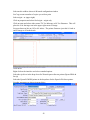
4.1.5.11Configuration of Wasatch Hot Folder
First setup hot folder. Click on Start Wasatch. Start > All programs > Wastatch Softrip >
Wasatch Softrip.
Select Unit 1 from drop down menu
Click on Server, Hot Folder
27
Select Active, Create Preview Images, Rip and Print, Delete Postscript after RIP, Delete
after Printing. Click on Browse and select Hot Folder defined earlier
C:\Program Files\Allen Datagraph\Cutter Driver\b500
Click Ok
4.1.5.12Setting Up the B500 in Wasatch
To setup your Wasatch SoftRIP to manage your Epson B500 printer, follow these
instructions:
1. Wasatch SoftRIP is still open.
2. Click on the setup icon
3. Click the PRINTER MODEL dropdown menu and select EPSON then B500DN
from this menu.
4. Change the physical connection to EBSON B-500DN
5. Change Imaging configuration to
ADSI_EpsonB500_720x720_BOPP_Bidirectional. Note if you have matte media
loaded use the matte imaging configuration.
6. Click EDIT and then PROPERTIES. Make sure paper source is set to Roll Feed
(rear) and width is either 4 to 8.5 depending on media width loaded.
28
If you want to change dpi, select the dpi you want from Print Mode drop down.
You can also increase to 1440 x 720 by changing Media Type to Photo Quality
Ink Jet Paper and then select DPI with Print Mode.
7. Click Ok, Ok,
8. Click Set Maximum Width and uncheck Width Center. Click on Set Maximum
Height and uncheck Height Center.
9. Click Ok.
4.1.6 Software Updates
From time to time, ADSI may update software, You can check for updates after the
product ships will be available on the tech support section of the
http://allendatagraph.com web site. Remember the rule: if its not broken, don't fix it.
You can check for updates by clicking on “What's New in Tech Support” link at the top
of the online documents page.
To update to a later version of software when recommended to do so by the tech support
department, go to the web site. Click on Tech Support, then Online Documents.
Select Axxis SR from list of selections.
Find the software update and click on it to download the setup program from the web
site.
29
5 Operation of the i-TECH AXXIS SR System
5.1 Setting Up Your Label Job
The target should be a black rectangle on white media or a contrasting color to
background. See colors in Web Site Copy or CD Copy. The recommended Mark Size is
0.25 inch by 0.5 inch (6 mm x 12mm). When printing process colors on white media the
best color is usually black.
The mark should be placed at least 0.25
inches (6 mm) from the edge of the
media and the spacing between frames
should be at least 0.25 inch (6 mm).
The number of rows and columns of
labels between registration marks
defines a “frame” of labels. A frame
of labels can be one row or several
rows of labels. There are several aspects to consider when deciding how many rows of
labels to print on one page. The main consideration is the trade off between speed (it
takes a about second to perform the find origin (FO) command and scan the registration
mark) and registration accuracy. The more often you scan the registration mark (the
closer the marks) the more accurate the cut registration will be. If the job allows for
overprinting the cut line, then registration may be less critical and eliminating some of
the registration marks can speed the job. Generally registration marks should be placed
at least every 12 inches (305 mm) on Axxis. Best practice is to print registration marks
for each row then adjust the cut job to skip one or more marks if desired. This procedure
also insures equal spacing of the labels and gives complete flexibility for cutting. The
distance between jobs, (the last cut line of the previous frame and the target on the next
frame) must be between -4 and 4 inches (101 mm). If the distance between frames is less
than the scan length, then the target must be outside of the area where the labels are
printed. Maximum frame size is 10 inches (35.5 cm)
5.2 Explanation of SmartMarkTM
The theory of operation relies on the SmartMark sensor sending an analog signal to the
embedded computer during a scan. The data is analyzed after the scan to automatically
create a threshold, find the edge of the target and eliminate noise. The Axxis scans the
mark in both x and y directions and calculates the intersection of the 2 scans. The Axxis
computer then assigns that intersection as the 0,0 point of the Axxis
coordinate system and matches that to the origin point (minimum x,
minimum y) of the HPGL cut file.
The Axxis uses a special HPGL command, FO, to start the registration
mark sensing function. It automatically re-registers the coordinate
each time the FO HPGL command is received. As part of the setup a
“x move between jobs” is input via the printer driver options which
moves the sensor to the approximate position of the next copy’s or
next frame’s registration mark. The Axxis expects the target for the
next frame to be within ½ the scan distance of the end of the frame.
30
The interface prints a 2 inch x 0.25 inch target bar to locate the images in the print. The
software should automatically find the first target and then proceed through the number
of printed copies.
If you get a target error “tar1” displayed on the cutter front panel display, the Red LED
pointer must be manually positioned with the joystick buttons at the approximate 0,0
coordinate position, then press select to reactivate cutter and clear error.. The
SmartMark system automatically repositions the sensor for subsequent copies.
The positioning process must be repeated if the joystick buttons are used. This is helpful
because it allows the system to be reinitialized when needed. Some printers require a
leader between jobs and this feature is a very easy way to deal with the issue.
Once the LED pointer is positioned as shown, the SmartMark is ready to operate and
will scan the registration mark when it receives a FO command in the job stream whether
on the first copy or on subsequent copies. Since the FO command is embedded in the
beginning of the cut file the scan of the registration mark is performed at the beginning of
each copy or frame of labels and on subsequent copies.
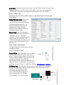
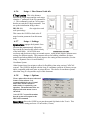
5.3 Types of SmartMarkTM Scanning
There are five types of SmartMarkTM scanning
available. They are shown in the image to the
right. The scan type is selected in the printer
driver preferences selected by clicking on
properties in the Print and Cut Extensions.
Origin Only is the only type normally used on
the SR.
Origin Only is used on printed media where you want to cut out preprinted labels.
Origin Only does a alignment with the visual sensor at the origin only.
Edge is used when you are cutting blank label stock. Edge offset is used only when
cutting blank labels on unprinted material. By selecting EDGE in the driver's printing
preferences menu, the SmartMark sensor will detect the edge of the media instead of a
registration mark, then offset into the media by that amount and cut your blank labels.
Origin Skew is used if the media is not necessarily loaded straight. This scans the origin
and the skew mark and rotates the cut image to match the cut location at the two scanned
locations. Since the Axxis keeps the media straight you do not normally need to scan the
skew mark. No scaling of the cut image is performed with Origin Skew scanning.
Origin Skew Scale does alignment at the origin, rotation and scaling in both x and y axes
are preformed. This scan type requires that the sensor size parameter be correct so that
cut image is same size as printed image. Normally the y axis does not have any scaling
errors on the printer so you do not need to correct the skew point and scaling at the scale
point.
Origin Scale does alignment at the origin, rotation and x-axis only scaling at the scale
point. It assumes that the scaling in the y-axis is correct. Normally you do not need to
scan the Scale location because if you have a scaling error in your printer it is normally in
31
the x axis and it is very consistent. If the printer you are using has a x axis scaling error
you can normally correct this either in the printer or you can use calibrate to printer to get
the Axxis to cut the same size as the printer.
5.4 Designing Labels
5.4.1 Planning Label
This tutorial will design a label for the Axxis SR with Inkscape and Illustrator.. It will
show how to create a bleed area to minimize visual errors on the completed label. First
we define our layout for a set of four 3x5 labels so we can create a set of locations in the
artwork generation program workspace. We lay out the frame with the x axis (media
movement going up and down on the screen and the y axis (operator/front to gear/back)
left to right. The target in this orientation appears in the upper left corner of the screen.
This allows for no rotation when the sending the job to the printer.
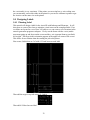
First create 4 labels that are 3x5 with 0.25 inch between each label
Then add the target in top left corner of 4 labels
Then add 0.50 bleed on one label
32
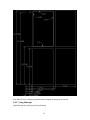
Offset all left right coordinates by 1 inch so they are all positive.
Complete design for label layout is shown on next page.
33
Now that we have workspace planned choose program to design your artwork.
5.4.2 Using Inkscape
Open Inkscape by selecting icon from desktop.
34
Turn on layers menu (Layer > Layers or Shift + Ctrl/L)
Turn on Transform menu (Object >Transform or Shift + Ctrl/M)
Select File > Document Properties. Change default units to inches (in)
Select custom size units in inches (in) set width = 7.25 and height to 10.45
On layer menu click on plus to create a second layer and name it dielines
Double click on original layer name (layer 1) and change its name to print
Select print layer.
Select rectangle tool
and draw a rectangle of any size any position.
Select Object > fill and stroke (or shift + ctrl/F)
Select stroke paint and click on x for no stroke.
Select Fill and change color to C-0, m=0, y=0, k=100 a=100
Set rectangle parameters rx=0, ry= 0, x=0.5,y=10,w=0.25, h= 0.5, stroke = none, fill =
solid.
Select rectangle tool
and draw a rectangle of any size.
Select Object → fill and stroke
Select stroke paint and click on x for no stroke.
Select Fill and change color to C-0, m=0, y=0, k=85 a=100
Change the rectangle properties to x=1, y=0, w=3,h=5,rx=0, ry=0
Note: if you have a stroke on the edge of the printed target the print and cut
will not line up.
Import the bitmap of the image to print from the cd path (File >import or ctrl/I).
(techsupport\axxis\sr\samples\inkscapelabel\ICON_Axxis_Cutter.bmp)
Using Object > rotate 90° and move to center image within the bleed area..
Select black square and imported label and group them with object group
copy label to following locations
1,5.25
4.25,0
4.25,5.25
Lock the print layer.
Next create the die lines. Click on the dielines layer on the layer selection.
35
Use rectangle tool
arrow
and draw a rectangle of any size in window. Click on select
and enter 0.25 for H and W and 0.5 and 10 for X and
Y. Click on node edit.
convert to path
then
and then your rectangle, and then
. Select lower right corner of rectangle and
to delete the corner. Next select diagonal line and delete
segment
. Open fill and stroke menu with object > fill and
stroke. Select object and set fill = x and stoke paint = flat color
Click on white to deselect and you are left with target alignment
mark.
Next use the rectangle tool
to draw a rectangle anywhere, any size. Set rx = 0.25,
ry = 0.25. Select the rectangle set X= 1.05, y= 5.3, w = 2.9, h=4.9
Using copy, paste, change x and y positions of copies of rounded rectangle to each of the
following relative positions from the first rectangle.
1.05,0.05
4.3,5.3
4.3,0.05
The dielines layer is now complete.
Finally you have to make the print and the cut image the same size in the up/down
direction on the screen. You do this by adding either a printed line or a cut line at the
bottom of the image to make the sizes of the print and cut the same size.
This completes the image
5.4.3 Using Adobe Illustrator
Open Illustrator click on start > all programs > Adobe > Illustrator, and Select Create a
new document from menu. (File > New)
Change units to inches by selecting inches from units drop down.
Click OK
If rulers missing, click on view -> rulers (Ctrl/R)
If layer menu missing, click on window -> layers (F7)
If color menu missing, click on window -> color (F6)
Now create two layers. One called “dielines” and one called “print”. This is done from
the layer window. Click on new layer button. Then rename the layers as dielines and
print by double clicking on layer name, changing name and clicking on OK.
First create the print. On Layer menu select print layer
36
To create the target, click on rectangle tool
for size.
, click on layout window, enter 0.25, 0.5
Using transform panel move lower left to 0.5,10
On the color menu select Fill and change color to black
Change out line stroke to none. The target color should
look like this when you are done.
Note: if you have a stroke on the edge of the printed target the print and cut
will not line up.
To create the bleed background, click on rectangle tool, then click on layout
window. Width 3, height 5
Move lower left corner x = 1, y = 5.25
On color window, select cmyk fill to k=85 cmy=0,
and no stroke on color menu
Now paste logo in foreground of label by File >
Place). (I used file
techsupport\sr\samples\illustratorlabel
\ICON_Axxis_Cutter.bmp.) Now size and center
label on grey background just created.
Select background and foreground of label. Then
click on object -> group
Then click object -> transform -> move (Shift +
Ctrl/M). Enter distance of 3.25 angle 0°, then click
on copy button.
Select both print labels
Then repeat move the with distance 5.25 angle 270°
and click on copy button.
This completes the print layer.
Next create the die lines. Click on the dielines layer on the layer window.
Create the die line for the target
Click on line segment tool
layout area
and then click on
Enter length 0.125 and angle = 0°
Click on object -> transform -> rotate enter 90° and
click on copy.
Using transform panel move top of vertical segment
to x = 0.5, y = 10.25.
Move left of horizontal segment to x = 0.5, y = 10.25.
37
Click and hold on the rectangle tool then select rounded rectangle from tool menu
and
then click on layout window. Enter the 2.9 for width, 4.9 for height and 0.166 for corner
radius. Open transform panel by going to windows > transform (Shift + F8) move object
so the lower left corner is at 1.05, 5.3.
Then click object -> transform -> move (Shift + ctrl/M). Enter distance of 3.25 angle 0°,
then click copy.
Select both rounded rectangles.
Then click object -> transform -> move. Enter distance 5.25 angle 270°, then click copy.
This completes die line layer
Finally you have to make the print and the cut image the same size in the up/down
direction on the screen. You do this by adding either a printed line or a cut line at the
bottom of the image to make the sizes of the print and cut the same size.
This completed label file is at this link Web Site Copy / CD Copy.
Use File -> save to save the file on your hard drive.
5.5 Webbing the SR
Refer also to the Epson's instruction guide ("Using the Epson B-500 with Roll Media")
that was included with the B-500 roll printer, before threading the web - especially the
"Loading Roll Media" section of the instruction guide
38
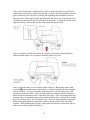
Take a roll of media with a width between 4 and 8 ½ inches and place it on the infeed
mandrel of the print station, lining it up with the very back edge of the mandrel. Once the
paper is lined up, lock it in place by twisting the red handle on the mandrel clockwise.
When you have fed the paper around and underneath the dancer bar, Feed the end of the
roll media into the manual feed slot at the back of the printer. Looking down from above,
align the left edge of the media with the white plastic tab shown below.
Once it is straight, guide the media into the slot until you hear the printer feed motor.
Hold the media in place for 3 seconds or until the printer feeds it in.
Once red into the printer you can feed the media all the way through the printer, hold
down the button on the printer control panel. Continue feeding media until enough to
web the machine. It will go around the guide bar then over the next dancer bar, then
through the lamination roller. Attach your lamination by going around the Lamination
dancer bar and in lamination roller, center and close roller. Now feed enough material to
go down and up accumulator chute and out of the machine. Once, material starts feeding
press F2 to take up slack. Press F2 again to stop. Now web material under accumulator
then back up and through the cutting bed, under the brush, and out of the side of the
machine. While holding media in place, adjust pinch wheels to be an inch from edge of
media, then lock then pinch wheels down.
39
{Caution: NEVER pull roll media through the printer with your
hands or you may damage the printer. Always use the and
buttons to feed media.} Check to make sure the media is straight all
the way through the "web" (paper path of the roll media feeding system).
Adjust the media position, if necessary.
The brush is designed to just touch the media to hold it in the correct position for the
SmartMarkTM sensor. No pressure need be applied.
40
5.6 Printing and Cutting
5.6.1 Print and Cut Interface
5.6.1.1 Print and Cut from Inkscape
Open sample techsupport\sr\samples\chapstick.svg or image designed above from cd in
inkscape
Use layers command and hide dielines layer
Click on Extensions > ADSI > Print and Cut
Use 720 dpi for export window then click on apply
5.6.1.2 Print and Cut from Illustrator
Open sample techsupport\sr\samples\chapstick.eps from cd in illustrator
Open layer menu with f7 key
Select the dielines layer
Click on File > Allen Print and Cut
Use 720 dpi and white background for export window that shows up.
5.6.2 Printing and Cut
From the drop down between Print & Cut and Properties select the DirectCut cutter
driver installed above.
41
Select media width as shown in Wasatch configuration window
Set Copy count to number of copies you wish to print
Select origin = ur (upper right)
Click on properties and select find origin = origin only
Click on rotate and select either rotate 270° for Inkscape or 90° for illustrator. This will
place the L for the target cut in the upper right corner of image.
Set space between jobs to 0.85 to 0.9 inches. The printer firmware eject this 0.9 inch at
end of image to clean the heads.
Click on Ok.
Right click on the interface and select extended options
Select the rip driver in the drop down for Wasatch port redirector printer (Epson B500 dn
for rip)
Select the Epson B-500DN printer in the dropdown for the Epson b500 direct printer.
Set other parameters as shown in menu below
Click on close window
42
Click on Print and Cut.
Verify you have done all the items in the check list and click on OK.
When you have finished printing click on the Eject button in the Allen SR interface to
have printer print the about 48 inches of media bring all the labels out of the machine.
5.6.3 Collate
The collate interface allows creating a set of labels to be printed. Once the individual
labels are designed and exported to the interface you can organize the set of labels for the
machine into a label set. You can then open the interface, choose the set of labels to
print, select the number of copies and media width and click on print and cut.
First extract the samples from the cd (techsupport\samples.zip) to your My Documents
folder. This will create a “label set” directory with some samples preloaded.
If you are adding labels to a label set open the label you want to add. If you are not
adding a label to a label set open any label that has a dielines layer.
The collate interface is selected by clicking on file > Allen Collate from illustrator or
Extensions > ADSI > Collate from the Inkscape program.
After entering the dpi and clicking on Apply or OK, the label set interface screen will
then be displayed.
43
The top directory will default to your My Documents folder and the sample label sets you
extracted above.. If you want the saved data for you label sets to be stored in a different
directory you can change it by clicking on the “...” button. The label set information and
pre exported plot and graphic images are stored in this directory. You should not change
the contents of this directory with except to delete a pair of files, (png/ink) or (png/ill)
with same name.
To create a label set, you click on tne New Label Set button and enter its new name.
Once you have created a label set, you can add a new label to the set. Clicking on Add
New will add the just exported label to the set and record the dielines and print file the
the base directory. If you want to add a previously exported label to the set, click on Add
Exist button and choose a previously exported label from the list. To control the order of
the labels in set, click the green up/down arrow button.
If you want to add more than one new label to the set, add the first label to the set and
then exit the label set interface. The interface will ask if you want to save the changes to
the label sets database. You should always save your changes by clicking on Yes, unless
to don't want to keep the changes you made.
To delete a label from a set, select it from the labels in set column and click Delete.
You only need to set the rotation property in the printer driver. Use 270° for Inkscape
files and 90° for Illustrator files. The SmartMark cut target should appear in the upper
right corner of the preview if you have set the rotation property correctly.
The print space is the space the printer automatically outputs at the end of each print.
This is normally 0.85 to 0.9 inches.
44
The Width is the width reported by Wasatch when you click on the Max Width button.
The cutter driver appears in the drop down next to the Print and Cut Set button.
Once you have created the set and changed the number of copies you can click on Print &
Cut Set to print and cut the job. You can eject all the printed material by clicking on
Eject.
5.6.4 Variable Data
To print variable data you must create a tab delimited file using Excel program and
clicking on File > Save As and change the files of type selection to tab delimited. The
first line of the file must contain the field names. If you have the file in a database you
can use Microsoft Excels get external data function to get the data out of the database.
So the data file should look something like this before you save it.
Name
Address
City State
John Right
39448 E Hampton
Aurora, CO 89923
Mary Wrong
3944 S Hudson
Atlanta, GA 39932
Allen Datagraph
56 Kendall Pond Rd
Derry, NH 03038
Once you have created the tab delimited file, create a label where you want the data from
the data file inserted. The file must contain at a minimum the printed and cut target and
some indication on the print as to where you want to put the data from the file.
Once the label file is created use Illustrator File > Allen Variable or Inkscape >
Extensions > ADSI > Variable Data. Select 720 DPI for export as you have for other
print and cut methods. The Variable Data user Interface is then displayed.
45
To use the just exported image click on Add New. To use a previously exported image
select it from the image select drop down. The sample image opened in Inkscape was
techsupport\sr\samples\address Variable.svg.
Next load the data by clicking on Load Data.
Since we have made room for 6 records in the image set RPI (Records per image = 6). If
you design with a different number of records per image enter the number of records used
by the image.
In the Field List you will have 6 copies of each field
The Field without a dash “–“ is the first record, the -2 is 2nd record, -3 is third, and so on.
There is an extensive drop down menu when you right click as well as predefined hot
keys. These functions are described below:
Next Field shows the image with next set of 6 records from the loaded data.
Using Multiple Field Command
46
Select the command you want by right clicking on the screen or entering the hot key from
the keyboard. Then select one or more marqees you have already drawn. Then select
End Command or CTRL/E character from the keyboard.
Rotate 180° rotates the insert in the marquee. You don't need other rotation as you can
draw the marquee field taller than wide or wider than tall to select other rotations.
Same Size x & y allows making a set of marquees all the same size as the first selected.
Same Size x allows making the marquees selected the same width as the first marquee
selected.
Same Size y allows making the marquees selected the same height as the first marquee
selected.
Align (left,right,top,bottom) allows making the left, right, top or bottom location of the
selected marquees the same as the first selected.
Equal Space Horizontal, Vertical makes the space between the marquees the same as the
first two marquees selected.
Delete At Cursor deletes the marquees selected.
End Command ends one of the above command.
Other Commands and drawing, moving, and resizing marquee's
Show Marquees allows displaying or hiding the marquess defined.
To create a new marquee, select the field you want to draw the marquee for from the field
list and drag a rectangle on the image where you want it to appear..
To move a marquee, move the mouse to a corner and drag it to where you want it.
To expand or shrink a marquee move mouse to center of line you want to move and drag
it where you want it.
To draw vertically make the marquee taller than wide.
In our example, after drawing the 18 marquees for the Name, Address, City State variable
image and aligning them we can see a preview like this.
47
You can click on Verify Size to verify that all data will fit in each marquee.
Click on Dieline tab, then click on Properties and set Rotate printer property so target L is
cut in upper right of screen.
Set width of media by entering it in the Width box to same as displayed in Wasatch after
clicking on the Set Max Width.
Set space between jobs to 0.85 to 0.9.
Click on Print and Cut
Select which record you want to print and click on OK
48
5.7 Axxis Web Tension Controls
5.7.1 Printer Input Dancer
Remove 8 screws as shown
Remove the 8 screws indicated. Adjust counter balance weight to set the tension. Set for
more tension if motor does not turn off. Set for less tension if print size is not to scale too
small.
49
5.7.2 Print Dancer Tension
To adjust tension of print dancer reach hand into machine just in front of printer, Loosen
set screw. Adjust position of counter weight on arm as shown in photo. If you have
stretching of printed image you need less tension, if print dancer does not pull media to
full position you need more tension.
5.7.3 Laminate Tension
The tension setting on the back of the Sr allows controlling the tension on the laminate..
You should use more tension on wider materials and less tension on narrower materials.
If you are seeing drift left and right, or laminate is not laying down smoothly, you
probably need more tension. If the laminate stretching you should use less tension.
You might need more tension on the print dancer if you have more tension on the
laminate dancer.
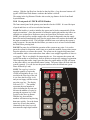
5.8 I-Tech Axxis SR Remote Panel and LCD Panel
The Axxis has a 4 digit display and a 16 button panel. The display is used to interact
with the operator showing current status. If the menu is not active the first digit is C for
cut, 2nd digit is speed (0 = 0-4%, 1= 5-14%, 2= 15-24% ...), and last 2 digits are force.
50
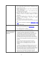
5.8.1 i-TECH Print Cut remote panel
The remote panel is installed earilier. It appears as an icon on your desktop and in the
start menu at Start -> All Programs -> Allen Datagraph. Double click on the icon on the
desktop to start the remote panel.
5.8.2 Action Menu
5.8.2.1 Save / Restore Calibration
This command saves line sensor parameters that depend on the calibration and calibration
of the Axxis or allows loading the calibration parameters from a file. It also allows
backing up your settings to your hard
drive in case of inadvertent operator
changes to settings.
5.8.2.2 Load / Save Settings from
Cutter to File,
These commands save the settings
(see setup settings menu) and some
line sensor parameters that are in the
Axxis to a disk file or loads settings
saved by this command from a file
and sends them to the Axxis. This
allows you to have more than 6
setups for different materials. It also
allows backing up your settings to
your hard drive in case of inadvertent
operator changes to settings.
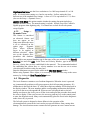
5.8.3 Setup > Main Menu
The Main menu opens the main menu window. The top window shows the model
number and firmware version (build 23 in the sample). The media height window shows
the maximum dimension the y axis is set to cut. The AXXIS will send this dimension
(called the clip limits) to the software program so that the software program can
determine if the specified cut file will fit. If a file with dimensions larger than the clip
limit is sent to the AXXIS, the cut will be truncated. The position window shows the
current location of the knife in the AXXIS coordinate system. The Last Saved Error
Message window displays the last error. Errors displayed here may be old. The error
may have occurred earlier in the AXXISs life. The Clear Error button clears the memory
of the saved error notification. Some features are advanced and only appear if menus =
advances is selected in setup → options.
51
5.8.3.1 State Tab
The State radio buttons allow the user to set the condition of the AXXIS. Unload means
the AXXIS is not loaded and is not ready to receive a cut file. The Pause radio button
means the AXXIS is currently paused and the Ready button means the AXXIS is loaded
and ready to receive the cut file and proceed with cutting. This set of buttons duplicates
the Load and Pause buttons on the front panel.
The Cad Override radio buttons enables or disables the CAD override function. With
the function On, the AXXIS will ignore some of the HPGL control commands sent from
the cutting software. With the function Off, the software can control these HPGL
functions. Some CAD systems will work correctly only when this feature is set to on.
These commands include:
AS
set acceleration
FS
set force
KA
set minimum angle
KN
set knife offset
IP
input P1/P2
RO
rotate
SC
set scale
SP
select pen
ST
select tool
UV
up velocity (move speed)
VS
down velocity (cut speed)
The Mode radio button sets the operation. Select cutting, pen plotting/drawing or
pouncing. The AXXIS will normally only use the Cut function.
The Dynamic Force radio buttons (an advanced option) engages the dynamic force
function, which instantaneously adjusts the force on the fly based on the actual velocity
of the knife blade. All AXXISs must accelerate and decelerate as they cut around
corners. Some medias require different force settings for different speeds. This
parameter allows for building a database for these materials and when enabled will
greatly improve the cutting on these materials. (See the Setup → Dynamic Force for
more details).
5.8.3.2 Knife Settings Tab
Draw Speed displays and sets the
velocity of the knife when it is
actually drawing or cutting. The draw
speed is the speed the knife travels
around the periphery of the items
being cut.
Force displays and sets the cutting
force. The range of force is 1 to 100%
represent 10 to 550 grams of force.
52
Knife Offset is the distance between the center of the knife blade and the knife tip. Allen
Datagraph blades have a 0.012 inch (.030 cm) offset. If you have objects that do not
close correctly, you might have to adjust the knife offset to correct the problem.
5.8.3.3 Rubber Tab
This tab is not used on the AXXIS unless you are doing stencil cutting at high
force values.
Rubber Minimum Angle displays and
sets the angle between consecutive
vectors that when exceeded will invoke
the tangential emulation mode. At
angles less than the value set in this
parameter the AXXIS will move
between vectors without evoking the
tangential emulation mode.
Stencil Force is the force separation
between drag knife mode and tangential
emulation cut mode. Tangential
emulation cut mode is normally used for
rubber or very heavy material. The
AXXIS will normally not cut this type of
material so this value should be set to a
high force %.
5.8.4 Setup > Line Sensor
Clicking on Setup Line Sensor menu opens the
SmartMarkTM Menu.
5.8.4.1 Line Sensor Tab
Sensor Offsets - The SmartMark sensor is offset
from the center of the knife to the center of the
sensor. The sensor offset distance is preset at the
factory or during installation, but may need to be
adjusted on occasion. The AXXIS can
automatically calculate and set the SmartMark
offset and sensor size parameters. See drawing for
definition of sensor offsets. See TSB Title Calibration Web Site Copy / CD Copy
X/Y Sensor size is the offset from the exact center of the red dot of the SmartMark
sensor to the sense radius and may change based on sensor sensitivity or media
reflectivity. This parameter is best
set using the procedure in the TSB
above. The Sensor Size parameter is
only useful in origin scale and three
target scanning. If you are not using
53
these methods you can set the size to 0.02. The sensor size is included in the sensoroffset parameter.
Scanning Parameters
The AXXIS SmartMark system has adjustable scanning parameters to allow for
different size and style of registration marks. The primary parameters are the scan offset
and length. The ideal X and Y offsets are one-half the mark size and the ideal scan
length is two times the scan offset.
To set the parameters type in the desired numbers in the X Scan Offset, Y Scan Offset and
Scan Length. When you have entered the desired values click on OK. (see also section 5.2
Explanation of SmartMarkTM). The scan length should = the mark size.
x/y Scan Offsets This is the distance to move in x and y to perform the scan. It should be
1/2 the scan length. The signs of scan offset for origin target should be +X/+Y.
Scan Velocity (default 2) sets the speed of the scanning. Depending on the media and
registration mark contrast, this parameter may need to be adjusted. The better the
contrast in reflectivity the faster the scan velocity can be set. If you are experiencing
missed registration marks, you may need to reduce the scan velocity.
X move between jobs is the distance after the farthest excursion of the x-axis during a
frame that the AXXIS should advance to find the target in the next frame of labels. This
item is duplicated in the DirectCut printer driver as the space between jobs. These two
parameters are added together so set this value to 0.
Target Scan Direction sets the direction of the scanning operation. For single mark
origin scanning the default target scan direction is +X, +Y. There may be circumstances
where it might be desirable to reverse the scan direction. For instance, the mark might be
printed to close to the trailing edge of the preceding labels limiting the distance available
for scanning. In this instance, it might be desirable to reverse the scan direction in this
axis. Consideration must be given in the cut file because the inside edge of the mark will
be considered as the 0,0 point for the AXXIS coordinate system. This is an advanced
menu option and must be enabled on the setup > options page. See also Web Site Copy /
CD Copy.
5.8.4.1.1 Skew Tab
The SmartMark system can use
one, two or three registration marks.
In standard operation the AXXIS
only requires one registration mark
to accurately cut the die lines of
most labels. If, however, there is a
problem with the printing it may
become desirable to use multiple
registration marks.
54
When using two registration marks the
embedded computer in the AXXIS will
automatically scan both the Origin Point and the
Skew Point. This is helpful if the printing is
skewed in relationship to the media.
When using multiple registration points it is
helpful to understand the FO command and its
parameters.
X, Y Scan offset. This is the distance from the
skew point to perform the Y and X scans to find
the skew point. With the targets defined as
above, the +X, -Y is the correct signs for the
scan offset for the skew mark.
Scan Skew Point - A fourth scanning mode
is implemented that performs scaling and skewing by scanning only two marks (origin
and scale). This method assumes there is no scaling error in the Y-axis. (Specify the
Origin, Skew, and Scale mode in your artwork software). By selecting the scan skew
mark off, the AXXIS will only scan the Scale and Skew mark and perform X-axis scaling
and skew correction. This parameter should always be on unless your printer driver does
not support origin scale processing.
Target Scan Direction sets the direction
of the scanning operation. The skew
mark is normally scanned +X,-Y. See
Web Site Copy / CD Copy.
5.8.4.1.2 Scale Tab
X, Y Scan Offset. This is the distance
from the scale point to perform the Y
and X scans to find the scale point.
With the targets defined as above, the
-X, +Y are the correct signs of scan
offset for the scale target.
Target Scan Direction sets the
direction of the scanning
operation. The scale mark is
normally scanned -X,+Y. There
may be circumstances where it
might be desirable to reverse the
scan direction. See Web Site
Copy / CD Copy.
55
5.8.5 Setup -> Settings Menu
The AXXIS allows six factory or custom set-ups.
Set-Up 1, whether standard or modified, is automatically loaded at power up. A user may
modify the speed, force, (or any feature) on the control panel. See key command
summary. Changes to a Set-Up, unless saved, will be in effect only until changed from
the control panel, CAS software,
the unit is turned off or reloaded.
Any of the features shown in the
Setup Form may be saved to one of
the systems 6 memory locations.
To save a custom set-up simply fill
in the desired value(s) in the
appropriate window, including the
Setup Number, click on the Save
Setup button. Some features are
advanced and only appear if menus
= advances is selected in setup →
options.
To load the edit boxes with the
current system parameters, input
the setup number in the Setup Number window and then click the Load Setup button.
Setup Number sets the memory position.
Draw Speed is the velocity of the knife when cutting (e.g. while the knife is down).
Move Speed is the velocity of the knife when in the up position (not cutting).
Force controls the down force or pressure on the knife.
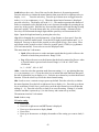
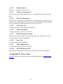
Knife Offset All drag knife cutters use a knife
CUTTER PATH
blade with the tip offset from the center of
rotation. As the AXXIS moves the knife trails
behind it, just like a caster on an office chair. In
order to accurately cut the outlines, the computer
embedded in the AXXIS compensates for the
offset of the knife. This parameter sets the offset
for those calculations. The figure to the right
shows the path the knife follows; the radius move at the corner allows for the knife offset.
There are three blades available from our online store our online store at
http://www.allendatagraph.com.
H20-017 30° Allen Datagraph i-TECH, DFS, Centra, Axxis cutting blade. Ideal for label
stock. Angle of blade at 30 degrees to have exact control on depth of cut. This blade has
a 0.012 inch (0.0305 cm) offset. It can be identified by its blue plastic cap.
56
H20-007 45° Allen Datagraph i-TECH, DFS, Centra, Axxis cutting blade. Ideal for
general purpose cutting of vinyl and other thin materials. Angle of blade at 45 degrees to
balance depth of cutting and pivot angle. This blade has a 0.012 inch (0.0305 cm) offset.
It can be identified by its red plastic cap.
H20-008 60° Allen Datagraph i-TECH, DFS, Centra, Axxis cutting blade. Ideal for
cutting thick materials. Angle of blade at 60 degrees to optimize cut angle. This blade
has a 0.012 inch (0.0305 cm) offset. It can be identified by its green plastic cap.
Minimum Angle The AXXIS must stop and then accelerate whenever it makes a sharp
turn. At shallow angles the AXXIS can continue at the cut velocity without decelerating
then accelerating. This parameter sets the angle where below which the AXXIS can
continue without stopping. High values increase throughput and lower value increase
quality. Good quality can be obtained at reasonable speed at the default value of 12°.
Hole Distance displays and sets the distance between holes when the AXXIS is used in
the pounce mode.
Tear Size displays and sets the hole size created when the AXXIS is in the pounce mode.
Acceleration displays and sets the servo acceleration. The unit of measurement is 1/4
G’s or 8 feet per second per second. This parameter is more important in small graphics
than in large labels or text. A setting of 2 to 8 is generally the best for most label cutting.
This parameter does affect throughput speed on graphics with short vectors. As the
graphics get larger the effect of higher acceleration diminishes. Higher acceleration can
degrade cut quality. Use smaller acceleration numbers for heavy materials.
Load Speed displays and sets the speed of the material loading and the speed of the
material pull off in the service loop mode.
Load Length displays and sets the length of the material that is pulled during the load
cycle and service loop if the AXXIS service loop mode is on.
Service Loop This should be turned off on the AXXIS when the AXXIS is in the
Label Mode.
Cad Override On or OFF enables or disables the CAD function. With the function On
(disabled), the AXXIS will ignore some of the HPGL control commands sent from the
cutting software. With the function Off, the software can control these HPGL functions.
These commands include:
AS
set acceleration
FS
set force
KA
set minimum angle
KN
set knife offset
IP
input P1/P2
RO
rotate
SC
set scale
SP
select pen
ST
select tool
57
UV
VS
up velocity (move speed)
down velocity (cut speed)
Mode sets the operation mode. Select the operation mode cutting, pen plotting/drawing or
pouncing.
To restore the factory default to all setups click the Restore Default button.
To load a setting enter setting number desired and click on Load Setup.
To save a setting enter setting number desired and click on Save Setup.
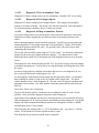
5.8.6 Setup -> Options
Menu
The options menu displays and
sets the following parameters:
Auto Origin Offset determines
whether moving the joystick
automatically sets the origin to (0,0).
Most CAD systems and the Allen
DirectCut printer driver require this
option to be set On. Set to Off when
cutting from a CAD system that
does not use the SmartMark
sensor such as the Gerber Omega
software.
Language determines which language the AXXIS uses. Select HPGL for most cad
systems and the Allen Printer Driver. If you are using Gerber Omega select Gerber. If
your cad system only outputs dmpl you can select this language.
Menus option offers the more advanced features of the software.
It is recommended this be set
to Normal until a more advance feature is understood or is required by your operation. The menu
items below are displayed when the menus is set to Advanced
Units sets the units of measure to English or Metric units.
Model sets the model number. Password for model number change is 23. Do not change
the model number unless you know what you are doing. The model number for the SR is
218.
5.8.7 Joystick
JOYSTICK The joystick is used for positioning the
knife and media in the die cutting station.
The four ARROW KEYS are used to jog the
material or AXXIS carriage that holds the knife
blade and the SmartMark sensor. With the
Jog/Slew box unchecked so that Jog/Slew = Slew,
the joystick speed will be the speed set in the
Joystick Speed Window. Left Click and hold the arrow button to move the material or
58
carriage. With the Jog/Slew box checked so that Jog/Slew = Jog, the arrow buttons will
jog the AXXIS that fixed distance each time the button is clicked.
The setting in the Jog Distance Window also sets the jog distance for the Front Panel
Joystick buttons.
5.8.8 Front panel of i-TECH AXXIS Finisher
The front control panel is the primary user interface for the AXXIS. It is used for input
of speed and force as well as several other functions.
LOAD The load key is used to initialize the system and to load or automatically fill the
supply accumulator. Once the material is fed thru the media path and the nip rollers are
engaged (see section Error: Reference source not found Error: Reference source not
found), press the load key and the supply roller will start feeding media into the supply
dancer bar and will automatically stop once the supply dancer bar reaches the bottom and
the input accumulator is full. The load light will then come on to indicate the system is
ready to operate. Be sure that the label frame you want to cut is at least 2 inches behind
the llade before pressing load.
PAUSE The pause key will halt the operation of the system at any point. It is used to
pause the system for inspection, media jams or to pause the machine for any other reason.
Press the pause key to resume the system. The system can be jogged while paused and
will remember where it was and resume from where it was stopped regardless of where it
was jogged. This is very helpful for inspecting the cut. You can pause the system and
joystick the media or cut head away from its position to inspect the cutting or registration.
After inspecting the media, simply press the pause key again and the AXXIS will return
to the point where it was paused and resume cutting. The pause light will flash while the
system is paused. You can also use the pause button to enter the unload state (press
Pause followed by Load).
COPY The copy key is used to
input the quantity of copies the
AXXIS will digitally die cut. It is
used after the first copy of the job
is cut. Once the first copy is cut
and you are happy with the results,
press the copy key. The display
will read 0001. The number
represents the total number of
copies including the first one run.
Increase the number of copies by
pressing the up arrow key of the
joystick or the force up button.
Hold the key down and the
numbers will start moving slowing
then more quickly. Press the down
arrow key to lower the number.
Alternatively the force keys will
increment the single digits and the
L
P
LO A D
PAU S E
S
P
E
E
D
C
F
O
R
C
E
CO PY
TC
TEST
CU T
F1
SELECT
59
F3
speed keys will increment the 10’s digits. If you enter 0 the copy will stop at end of next
job. If you enter -001 then it will count up forever. Remember the number displayed
includes the first copy run before the copy key was pressed. Input the copy quantity and
start the cutting by pressing the SELECT KEY.
SPEED The speed keys are used for controlling the cut speed (the speed the knife travels
around the periphery of the items being cut). Increase the speed by pressing the up arrow
key. Decrease the speed by pressing the down arrow key. Hold the key down and the
numbers will start moving slowing then more quickly.
FORCE The force key is used in conjunction with the test cut key to set the depth of cut.
The range of force is 1 to 100% when the system is in the normal force range. For most
applications the normal force range is adequate. In the normal force range mode, the
force is adjustable between 10 and 550 grams of force in 100 steps.
The force is set by test cutting the media to be cut using the test cut
function. Using the joystick, position the knife in an unused portion
of the media and press the TEST CUT key. The system will cut a
test cut pattern similar to the diagram to the right. With a sharp knife
or tweezers you should be able to individually remove each part of
the test cut pattern working from the ring to the triangle without
affecting the remaining parts. A properly set force will leave a very
slight scratch or mark on the liner.
The force may need to be adjusted due to blade wear during use if problems with
weeding occur. Simply increase the force setting by one until satisfactory weeding
occurs. If the knife blade is changed, revert back to the original setting or perform the
test cut procedure again. The blade may need to be replaced if the force is increased by
more than 20 percent from when the blade was new.
F1 This key puts the pen up or down during digitizing mode.
F2 This key turns on/off the supply nip roller
F3 This key turns on/off the take up nip roller
RESET the AXXIS by pressing the F1, F2 and F3 keys in order.
JOYSTICK The joystick is used for positioning the
knife and media in the die cutting station and for
several other functions.
The four ARROW KEYS are used to jog the material
or AXXIS carriage that holds the knife blade and the
SmartMark sensor. Press the key once to move the
material or carriage slowly and press it a second time
within ½ second to move at a faster speed. Tap the key
to jog the AXXIS a fixed distance. The distance is
adjustable (see Joy section below or joystick in the
Remote Panel section).
60
SELECT
SELECT The select key is used to invoke the menu system. Press the select key and the
display will change to indicate the last used menu item. To select a menu item press the
select key and then press the right or left arrow key to scroll thru the various menu items.
With the desired menu item displayed, press the up or down arrow key to select the state.
When the desired state is displayed press the select key to input the menu item and state.
The menu items are: ACCL, CAd, diA, FILL, indE, JOY, OPEr, and Set.
Menu Items:
ACCL allows setting the acceleration in ¼ G increments. Acceleration is the rate of
increase/decrease of speed of the motors along a vector. Higher G values increase
throughput however higher G values also increase the likelihood of experiencing
repeatability problems. Recommended values are (2-8) for standard labels.
CAd override menu function enables or disables the CAD override function. This is an
advance function and is only necessary when using cad systems that are not designed for
the AXXIS. With the function On the AXXIS will ignore some HPGL control
commands sent from the cutting software. With the function Off the CAD software can
control these HPGL commands.
The commands affected by CAd override are:
AS
set acceleration
FS
set force
KA
set minimum angle
KN
set knife offset
IP
input P1/P2
RO
rotate
SC
set scale
SP
select pen
ST
select tool
UV
up velocity (move speed)
VS
down velocity (cut speed)
Press the select key to initiate the menu function. Press the left or right arrow key to
display CAd, then press the up or down key to toggle between off and on. Press the
select key to lock in the desired menu setting.
diA is used for entering into the diagnostic mode. Press the select key to initiate the
menu function, then press the left or right arrow key to display diA. Press the up or down
key to scroll thru the diagnostic numbers (0002 – 0099). Press the select key to start the
diagnostic. (see diagnostics section) . To exit from a diagnostic mode select 0099 and
press select.
FILL is used to add more material to the supply accumulator loop at any time during the
operation of the AXXIS. Press the select key to initiate the menu function, then press the
left or right arrow key to display FILL. Press the select key and the AXXIS station
will pause and the supply nip roller drive will start to fill the supply dancer bar loop.
Once complete the supply nip roller drive will automatically stop and the AXXIS will
resume. This is useful if for some reason either of the dancer bar loops have insufficient
material.
61
IndE indexes the x-axis. One of the uses for this function is for metering material.
Press the select key to initiate the menu function, then press the left or right arrow key to
display IndE.
Press the select key. Press the up or down arrow to toggle between
inches (InCH) or centimeters (cEnt). When the desired unit of measure is displayed
press the select key. The display will read 0001. The number represents the number of
inches or centimeters to be metered in the x-axis. Increase the number by pressing the up
arrow key of the joystick. Hold the key down and the numbers will start moving slowing
then more quickly. Press the down arrow key to lower the number. Alternatively the
force keys will increment the single digits and the speed keys will increment the 10’s
digits. Input the length and start by pressing the select key.
JOy allows changing the joystick parameters: of jog distance or slew speed. Press the
select key to enter the menu system. Press the left or right joystick buttons until JOy is
displayed. Press up or down on the joystick to select (Sped or Jog). Press select. Press
up or down on the joystick to select a value for joystick speed (1-100%) or jog distance
(0.01 inch increments). Press select to save the displayed value.
This menu item has 2 sub-menus:
•
Sped- Allows the user to set the maximum speed that the joystick will move the
material or head when pressed twice. Range 1-100.
•
Jog- Allows the user to set the distance that the head or material will move when
a joystick button is pressed and released. Range is 1-100 in 1/1000th inch
increments.
i.e., 1 = 0.001”, 100 = 0.100”
OPEr is used to select the operation mode between cutting (CUt), pen plotting/drawing
(drA) or pouncing (POUn). Press the select key to initiate the menu function, then press
the left or right arrow key to display OPEr. Press the up or down key to select the desired
function. Press the select key to lock the desired menu setting.
SEt loads or saves a custom set-up or power up default. Press the select key to initiate
the menu function. Press the left or right arrow key to display SEt. Press the up or down
key to scroll thru (LOAd, Save), press select, press the up or down key to scroll thru the
settings (1 – 6). Press the select key to load or are save the setting. Setting #1 is loaded
when the machine is powered up. (see also factory and custom set-up section)
The set menu item has 2 sub-menus:
Load- loads a setup.
To load a setting:
•
•
•
•
•
Press select
Press left or right arrow until SET menu is displayed.
Press up or down arrow to display Load.
Press select
Press up or down arrow to display the number of the setting you want to load (16)
62
•
Press select.
Save- saves a customized setting.
To save a setting:
•
•
•
•
•
•
•
Adjust force, speed, acceleration as needed.
Press select
Press left or right arrow until SET menu is displayed.
Press up or down arrow to display Save.
Press select
Press up or down arrow to display the number of the setting you want to
customize (1-6) (# 1 is the setting that is loaded on power up.)
Press select.
5.8.8.1 Mandrel Switches and Controls
On the right of the control panel there are two switches.
LAMINATION MANDREL controls whether the lamination mandrel will supply
media to web. Turn off if you are not laminating or loading. Turn on for laminating.
SUPPLY MANDREL controls whether the supply mandrel will supply media to web.
Turn off during loading. Turn on while in use.
6 Maintenance & Consumables
6.1 B500 Printer (refer to Epson Manual)
6.1.1 Substrates
The Epson B-500 uses Epson DURABrite ink, which is a water-based ink. It is
recommended that all substrates are coated with an ink jet compatible coating.
6.2 i-TECH AXXIS Finisher
6.2.1 Changing a blade
The knife blade should be replaced when the force has been increased by more than 20
percent or the cut quality has degraded. The first sign of blade degradation usually
occurs in the corners of the cut and may lead to poor weeding.
New blades slide into the holder to a preset height and are held in magnetically. No tools
or adjustments are required. To replace the blade, first remove the blade holder from the
tool holder by loosening the brass thumbscrew and pulling up on the silver knife holder.
Remove black plastic cap. To remove the used blade, grasp it with a pair of tweezers and
pull it out of the knife holder (discard the blade safely). Remove the new blade from the
plastic case and remove the protective cap. Insert the blade into the holder and let the
magnet pull it into the preset position. Install plastic cap. Reinsert the knife holder into
the tool holder and tighten the brass thumbscrew.
63
Replacement blades are available from several sources including from Allen Datagraph
Systems, Inc. They can be purchased online @ http://www.allendatagraph.com/ or by
calling 603-216-6344.
H20-017 30° Allen Datagraph i-TECH, DFS, Centra, Axxis cutting blade. Ideal for label
stock. Angle of blade at 30 degrees to have exact control on depth of cut. This blade has
a 0.012 inch (0.0305 cm) offset. It can be identified by its blue plastic cap.
H20-007 45° Allen Datagraph i-TECH, DFS, Centra, Axxis cutting blade. Ideal for
general purpose cutting of vinyl and other thin materials. Angle of blade at 45 degrees to
balance depth of cutting and pivot angle. This blade has a 0.012 inch (0.0305 cm) offset.
It can be identified by its red plastic cap.
H20-008 60° Allen Datagraph i-TECH, DFS, Centra, Axxis cutting blade. Ideal for
cutting thick materials. Angle of blade at 60 degrees to optimize cut angle. This blade
has a 0.012 inch (0.0305 cm) offset. It can be identified by its green plastic cap.
Tool Holder Block
The knife blade holder is installed in the tool holder block with a thumbscrew. The tool
holder block is held to the cutting head by two hex drive screws.
Knife blade holder Assembly
The blade holder is designed for use with Allen Datagraph’s 30°, 45° and 60° blades.
Solvents and lubricants should not be used, as they will diminish cutting accuracy.
Knife Blades
Knifes blades for the Allen Datagraph AXXIS Unit are made with tungsten carbide and
are designed specifically for digital die cutting. The tip is offset from the center of the
shaft so that the blade has a caster action when pulled. Blades are available in 30, 45 and
60-degree tip angles. The 60-degree is intended only for thick materials such as sandblast
mask or thick over-laminates. For best cutting results, protect the knife tip from damage
when not in use.
Knife Blades Depth Guide
Allen Datagraph's controlled depth knife holder has a depth guide that is adjustable to
control the depth of cut the AXXIS makes. Normal materials do not need to use the
controlled depth adjustment and the black plastic cap can be screwed in completely to
expose the blade. Material with insufficient backing may require the use of the
controlled depth cap. Correct adjustments allow the blade to cut the material and lightly
mark the backer (carrier) material. Too much cut depth can cause cut through and
premature blade wear. Not enough cut depth will make "weeding" of media difficult.
Use the cut test, force and depth adjustment to establish good cutting (see setting cut
force – cut depth section)
6.2.2 Changing a cut strip
Clean any debris from the groove before installing the groove filler. The filler simply
snaps into and out of place with no special tools required. It is important that the
groove filler be installed fully and evenly, otherwise material cut through may occur
64
in some sections across the cutter. The groove filler should be installed for knives and
pen plotting, but must be removed for Pouncing
Two different cut strips are available from the http://allendatagraph.com online store.
Normal life (DF-310) and extended life (DF-410) cut strips.
6.2.3 Cleaning
The regularity with which the cutter needs to be cleaned is dependent on the usage, as
well as the climate and contaminants in the cutter’s environment. It is recommended that
the following cleaning steps be done at least as often as indicated for each procedure:
•
Biweekly. Clean the three grit wheel surfaces with a stiff bristled e.g. tooth (not
wire) brush to remove any media particles that may have built up during cutting.
Brush the surface of the grit wheel while turning the grit wheel by hand so the
entire surface of the grit wheel is cleaned. CAUTION: Be sure to disconnect the
cutter from the power source while cleaning the unit. Keeping the grit wheel clean
is important so the cutter will hold the media accurately.
•
Biweekly. Wipe media-related dust from the set of polyurethane pinch wheels by
using a soft cloth.
•
Monthly. The outer surfaces should also be kept clean. If necessary, a mild
cleaning solution on a damp cloth can be used to gently wipe the surfaces clean. It
is suggested that a mild soap and water be used with a soft cloth. This solution
works well on all painted surfaces. CAUTION: Do not use any abrasive cleaners,
as they will cause the paint to blister.
•
Yearly. Inspect the internal circuit board assemblies and clean accumulated dust
as necessary. Be certain that the cutter power is off. Observe static discharge
safety procedures that may damage sensitive electronic components. Wear a
grounding strap connected to earth ground. Wear safety glasses to protect eyes.
Remove rear cover and use compressed air to remove dust and debris. Replace
cover to original location and make certain that the boards and any connectors are
well seated.
6.2.4 Pinch Wheel Maintenance
Pinch wheels are critical to the AXXIS unit's material handling performance. They
should be inspected for wear regularly and cleaned as needed. To clean adhesive off the
pinch wheels, simply use a soft cloth and denatured alcohol.
In normal use, the pinch wheels will need to be replaced in time. Also, trying to move
them when they are in the down position can damage them. If material does not track
well and guide alignment has been verified, the pinch wheels may need to be replaced.
For best tracking results, replacement pinch wheels should be replaced as a SET.
To check condition of pinch wheels:
Inspect condition of rubber The rubber wheel should not have any cracks and should be
securely adhered to the aluminum hub of the wheel. The transition from the flat surface
of the wheel to the "sidewall" edges of the wheel should be sharp and not rounded.
65
Inspect integrity of pinch wheel bearing This is done by having the pinch wheels in the
up position. Spin wheel with finger and observe whether the bearing has a dry sound or
not. If it appears to be dry, the wheels should be replaced.
Pinch wheels (p/n PL-00-02-062) can be ordered from the online store at
http://allendatagraph.com
6.2.5 Mechanical Adjustments
Belt Tension
The AXXIS servomotors use timing belts to control the material (X axis) and tool (Y
axis) positions. The belt tension and wear should be inspected if cut quality deteriorates.
To inspect the belts, remove the back of the AXXIS. This can be done by removing
about 4 large screws along the edge of the rear cover. (see also TSB: Mechanical
Adjustments to Restore Cut Quality to Normal Web Site Copy / CD Copy)
Y-Axis
The Y-axis short belt runs between the Y-axis servomotor and a gear assembly. To adjust
the tension of this belt, it is necessary to reposition the motor bracket.
•
Open the back cover (6 screws)
•
Loosen the three Phillips head motor bracket screws and apply hand pressure to
tighten the belt so that the belt will deflect 0.050 inches at the center when 23
ounces are applied. (1.3 mm when 660 grams are applied).
•
When the belt is tight and the motor shaft is parallel to the bearing shaft, tighten
the three Phillips head motor bracket screws. Premature belt failure will occur if
these two shafts are not parallel.
•
Verify tension.
•
Close back cover.
The long belt is adjusted using a lead screw located behind the control panel.
To set the long belt's tension:
•
Position the carriage to the far side.
•
Remove the control panel housing as follows
•
Remove the Allen screws that hold on the cover for the LCD display.
•
Loosen the locking nut.
•
Adjust the lead screw so that the belt will deflect 0.125 or feels taut. You can
also pluck it like a string and is should make a low tone.
•
Move the carriage slowly from two or three inches/cm front and back to
equalize tension on pulleys. Check tension again.
•
Set the lead screw lock nut.
•
Verify belt path and tension.
66
•
Replace the control panel housing, top rail cover and rear cover.
X-Axis
•
Open back cover
•
The belt inside the rear cover drives the grit wheel (X axis). To adjust the tension
of this belt, it is necessary to reposition the motor.
•
Loosen the two motor bracket screws and apply hand pressure to tighten the belt
so that the belt will deflect 1/16 inch at the center when 23 ounces are applied. (2
mm when 660 grams are applied). (Replace belt if damaged or worn).
•
When the belt is correctly tensioned, tighten the two motor bracket screws.
•
Verify belt path and tension. Check that the large gear turns freely.
•
Close back cover
6.3 Troubleshooting i-TECH AXXIS Finisher
Problem
Cutter does nothing
Cut through/poor
weeding
Images are incorrect
size
Solutions
• Panel lights off, no fan noise : plugged in, power on, cycle
power
• Check fuse replace with one 5A for 115 vac or two 2.5A
for 220 vac.
• E-Stop button pressed.
• Is your knife blade sharp? You can check condition of
blade by examining the blade tip under a 30x microscope.
The blade tip must be present.
• For very thin (less than 0.002 inch, (0.05 mm)) or liner less
than 20 lb. media you might need to use the controlled
depth adjustment on the end of the knife holder. Partially
unscrew the black cap until just enough knife blade is
exposed to cut through the media but not the backer. Test
by drawing knife across media by hand. You can then use
a higher force with no cut through.
• It is important that the groove filler be installed fully and
evenly, otherwise material cut through may occur in some
sections across the cutter.
• Insufficient backer weight.
• Check mechanical adjustments Website Copy / CD Copy
• Increase / Decrease force. Increase decrease knife offset.
• Check cut strip condition. Replace or reverse if damaged.
• Decrease acceleration or speed.
• Increase resolution in printer driver.
• Using wrong angle of blade for material.
• Not tracking. Fix this first.
• If error is small (< 1/2 inch (12 mm)) make sure grit wheel
is clean. Dirt build up in grit will change the size of the
67
Contour cuts are wrong •
size.
•
Labels or contour cuts
are cutting in the wrong
spot
Target errors tar1, tar2,
tar3, tar4
grit wheel making it cut the wrong size. Run diagnostic 07
to calibrate the cutter to a ruler or a printer as desired.
If you are using origin only or origin skew no scaling is
done to image received. In this case you must calibrate the
cutter to your printer rather than a ruler. You do this by
printing a large rectangle on your printer. Then cut the
same size rectangle. For x and y drawn use printed size
rather than a ruler as drawn or desired size.
If you are using origin scale, or origin skew scale then the
size of the cut is change by the x or y sensor size parameter
in the line sensor menu.
•
•
See SmartMarkTM setup in Appendix A
Verify you created job correctly.
•
Origin Target is at minimum x and maximum y of drawing.
•
The scan area contains only target and background with no
stray marks that could be seen as targets.
•
Verify printer properties are correct
•
Rotation is set correctly. Target cut should be in same
corner on preview as selected origin corner.
•
Find origin cutter driver property is not set correctly.
•
Verify sensor settings have not been lost
•
In the remote panel select setup -> line sensor menu.
•
Verify x sensor offset is about 0.75 inch and y sensor offset
is about –0.1 inch
•
If your job is off by only a little bit (less than 1/8 inch
(3mm)) and is same for every frame you can measure this
error and correct your x and y sensor offset by the amount
of the error you measure.
•
Verify scan length is the same as the length of the side of
the target
•
Verify the scan offsets = ½ of the length of the side of the
target
•
Verify the Scan Velocity is either 1 or 2.
•
Verify the space between jobs in the line sensor menu is
zero.
These errors indicate that the target scanner did not find the
target.
•
•
If tar1 on first frame:
68
o Check x offset distance
o Verify there is about ¼ inch white space on rear
edge of target bar.
o If no targets are present reduce threshold or
increase Thresh count, or increase max scan
distance.
o Verify red led is lit.
o Check that distance led is from media is 3.4 to 4.6
mm.
o Run line sensor diagnostic (21) to verify operation
of sensor.
•
If tar1 on 2nd or subsequent frame
o Verify space between jobs in printer driver is set
correctly. If it is set correctly after cutting first
frame the knife blade should be on the right rear
corner of target of next frame. Normally this is set
between 0.85 and 0.9 for Axxis SR.
o Check printed space between jobs is same for all
frames. If not check print dancer or input print
dancer tension.
•
Tar2 – 4.
o Verify job you are sending matches job you printed
o Verify rotation is correct in printer driver
o Verify job is built correctly in that scale and skew
target print is in same location is die lines for scale
and skew target.
No action when you
send data to cutter
•
•
o Verify scale and skew targets are at extents of
image. Skew should be a minimum x and
maximum y. Scale target should be at maximum x
and minimum y.
Allen Spooler: If plot is sent from computer and cutter
doesn’t cut, check for Allen spooler in the task bar (Lower
right of monitor, green box with red arrow, near time). If it
is not there, go to start button, programs (all programs),
startup, Allen spooler and click on Allen spooler. If you get
message saying Allen spooler starting with one job left in
queue, cancel it and send job again after checking to see
that cutter is ready.
Click on red arrow in green field icon in service icon area.
69
•
•
•
•
•
•
•
•
Job does not complete
When I turn my cutter
on, the head reaches the
side plate and makes a
loud noise
•
•
If you are getting unable to open port displayed
See if remote panel still has port open. It should auto close
the port after 5 seconds.
Reboot computer and power cycle cutter, cancel all jobs
and try send job again.
Verify port selected is correct. You can find the correct
port from the device manager.
Plug usb cable into same usb port as you normally do.
Different usb holes are normally configured as different
com ports.
Rerun enable printer driver to find cutter. Start > All
Programs > Allen Datagraph > Cutter Driver > Enable
printer driver
Try different usb cable or different computer.
From spooler cancel all jobs, turn cutter off/on and resend
job.
No usb driver installed for equipment Website Copy / CD
Copy
Cutter in pause state.
Verify minimum cutter driver level of 2.10a. New
software can be downloaded from Web Site Copy
•
Try a different cable or computer
•
•
Try using Ethernet for communication method
Loose long Y belt
if carriage is getting to the right side and making a
ratcheting noise, it's could be the long y axis belt, or the y
axis motor belt located under the left control panel. To
determine which belt it is, turn the machine on while
holding out on the long belt that attaches to the cutting
head. What this does is put more tension on the belt. If the
head gets to the side and they don't hear the noise, proceed
to below:
Remove the front control panel and locate the belt
tensioner. This is a wedge-shaped device with a long
Phillips head screw protruding toward the rear of the
machine.
Loosen the 3/8" locking nut holding the tensioner screw in
place. Turn the Phillips screw a couple turns clockwise,
then turn the cutter on before attaching the control panel. If
the cutter initializes, there is no need to look further. If this
does not solve the problem, proceed to the next step:
Open rear cover, turn cutter on and observe the belt
attached to the motor. If the motor pulley continues to turn,
70
•
Router keeps changing
my ip address
•
Material Does not track
straight
•
•
•
•
Lamination Not
Tracking
then the short motor belt is most likely either loose or worn
out. Carefully inspect the teeth on the belt for wear with the
machine off. The pulley can be rotated to allow inspection
of teeth.
If the teeth are not worn or stripped off the belt, loosen the
three mounting screws holding the motor bracket to the
sideplate. Apply tension to the motor bracket BY HAND,
and tighten the screws. The belt should have less than 1/8”
of free play when properly tightened.
Some routers do not keep a table of mac addresses so that
the same computer will be assigned same ip address each
time you power up. In this case run diagnostic 4 and
assign a static ip address to the cutter. See also Website
Copy / CD Copy
Inspect pinch wheels
Clean grit wheel and pinch wheels.
Reduce acceleration and / or velocity.
Insure cutter is loaded straight. Same distance from back
wall from supply to takeup.
•
Perfect leveling is not required in steps below but
adjustments need to be close.
•
Machine loaded per Webbing the SR
•
Machine Level (place level on cut strip) level with machine
/ table legs.
•
Adjustable bars level. Set level on Web guide 3, exit roller
and adjust until level.
•
Mandrels Level (to adjust remove back of machine and
loosen 4 mandrel leveling bolts. Align with Square. Check
with level. Tighten bolts.)
•
Skewing
•
Verify both left accumulator dancer bars are not bouncing
on bottom or top of service loop. Bouncing will cause the
media to slip between the grit wheel and the pinch roller.
Machine loaded per Webbing the SR
•
•
Machine Level (place level on cut strip) level with machine
/ table legs.
•
Printed media must be wound on core evenly
•
Laminate same width or smaller than printed stock.
Laminate with should be 1/16” to 1/8” smaller than printed
stock.
71
•
Too much pressure on laminate roller (blue rubber roller).
Only a light pressure is required on laminate roller.
•
Uneven pressure on laminate roller. To set pressure loosen
two nuts on each pressure control. These are the hinged
cam latches that supply the pressure on the blue roller. To
measure the pressure you need to create two sandwiches of
three pieces of the unlaminated printed media. Place one
sandwich under operator side latch and one under gear side
latch. Adjust the pressure the latch applies to the blue
roller until both centerpieces of the sandwiched media can
be pulled with the same amount of force. Test tracking.
After laminate tracking works correctly tighten lock nuts.
•
Mandrels not perpendicular to back plate.
A Appendix A – i-TECH remote panel Advanced Options
A.1 Enable Advanced Options
To enable advanced options select setup -> options from remote panel. Change
advanced/normal menu options to advanced.
A.2 Action Menu
A.2.4
Send HPGL File
Send HPGL File will send a HPGL plot file directly to the Axxis. Typical origins of
HPGL files include the Allen Driver, CorelDraw or some other design software. To send
a HPGL cutter file from the remote panel program click the Send HPGL File menu item
to open the select file window. Select the files desired and click the Open button. This
will send the file directly to the Axxis.
A.2.5
Cancel, Continue, Pause
These commands will cancel, continue, or pause a job being sent by the Send HPGL
command. For jobs sent by other programs you can use the Pause button on the AXXIS
and the (F1, F2, F3) combo to cancel the currently cutting job.
A.2.6
Open Com Port
Opens a communication channel to the Axxis and sets a long timeout for close.
A.2.7
Close Com Port
Closes communication port to cutter. Since only one program can talk to cutter at a time,
selecting this command allows other programs to talk to Axxis. The remote panel will
normally automatically close the com port after a period of inactivity.
A.2.8
Upload Firmware
The firmware on this disk is provided for update purposes only and should not be
installed on new machines. In general you should not install a firmware update unless
72
directed by a member of the technical support staff. Firmware updates are available on
the technical support page of the Allen Datagraph web site at
http://www.allendatagraph.com.
This procedure details the firmware upgrade procedure. Normally firmware is only sent
to customers when a software problem is reported that has been fixed in a later version of
the software.
From time to time Allen Datagraph will recommend that you upgrade your firmware in
your Allen Datagraph Axxis. A file
can be downloaded from the Allen
Datagraph web site and saved to the
desktop.
Before running the setup program be
sure to exit the older version of the
Remote Panel.
A.2.8.1
Firmware
Installation Instructions:
Turn off your equipment. Press the
load button on your front panel and
then, turn on the Allen Datagraph
equipment to be upgraded. Start the
Remote Panel by clicking on start, program, Allen Datagraph, Remote Panel. Click on
Setup, Com Port and verify that the correct port has a check next to its name. Click on
Action, Upload Firmware. If asked, select pic32rel.hex file and click Open. If the upload
fails, you will be given a backup procedure to follow on the computer screen.
A.2.9
Save to EEROM and Restore from EEROM
This procedure allows saving the eerom and restoring it when certain hardware is
replaced.
A.3 Setup Menu
These commands are used to save custom settings and factory settings to the computer
when certain electronic components need to be replaced.
A.3.4
Main Menu
Knife Settings Tab
The AXXIS will also self adjust the speed within certain limits based on the speed of the
device feeding the unit. The range for speed is 1 to 100%. Enter min and max speed
for Label Mode and check the Allow Speed Change. This option is only useful in
alternate hardware configurations. Not support on standard Axxis model.
Hole Distance and Tear Size are used when the AXXIS is in the Pounce Mode. The hole
distance setting is the distance between holes and the tear size is the distance the AXXIS
moves with the pounce tool down to tear the media and enlarge the pounced hole
73
The Rubber tab
Rubber Scratch Force displays and sets the down force used during tangential emulation.
This is primarily used when cutting thick materials such as sandblast rubber. Tangential
emulation simulates a tangential or servo controlled rotating knife by moving to a
position short of the vector to be cut and putting the knife blade down with a very light
force while moving toward the direction of cut to align the knife before applying the full
cutting force. This improves the cut quality in thick materials. (default 0.1%)
Rubber Backup Multiplier (default 20) displays and sets the distance the knife will be
dragged at the light force used to align it. This parameter is used with and is additive to
the Rubber Backup Offset (default 0.02). The Rubber Backup Multiplier is based on the
change of angle between vectors and the Rubber Backup Offset is a constant added to the
distance calculated based on angle.
Rubber Minimum Angle (default 19) is the rotation angle between two vectors that
enables tangential emulation. Subsequent vectors that have angle between them
exceeding this parameter cause the pen to be picked up, dragged along the surface to
align the knife and plunged into the media at the beginning of the next vector.
Subsequent vectors that have angle between them less than this parameter will perform a
drag rotation.
Max Motion Vector Length (default 0.001) (Named after the driver that outputs very
small vectors) Allen AXXISs very accurately replicates the vectors in the HPGL plot file.
Some design programs output vectors that are very short. It is sometimes desirable to
combine some of these vectors into a longer vector to eliminate jagged edges or slow
cutting. This parameter works like a curve-smoothing algorithm and is used to improve
poor HPGL files.
Anticipation Rubber (default 0.001) and Anticipation Vinyl (default 0.0004) is a parameter that
adjusts the backlash compensation in the AXXIS. The Anticipation Rubber is the
parameter used when the AXXIS is in tangential emulation mode and the Anticipation
Vinyl is the parameter used when not in tangential emulation mode. Heavier materials
require more backlash compensation. These numbers are individually set at the factory
and should not require adjustment except when cutting heavy materials. If you are
experiencing thick and thin lines or misshaped letters, adjust the anticipation parameter to
obtain satisfactory results.
A.3.5
Setup -> Line Sensor Skew tab
Y Target Location. This is the distance between the origin target and the skew target
when the 2nd parameter of the FO command is –1. This command is used on CAD
systems that do not emit the FO HPGL command. You set up the initialization string to
have
BJ1;FO-1,-1;
<for origin skew and scale processing>
or
BJ1;FO0,-1;
<for origin and skew processing>
This causes the AXXIS to look at the Y Target Location parameter from this menu item.
74
A.3.6
Setup -> Line Sensor Scale tab
X Target Location. This is the distance
between the origin target and the scale target
when the 1st parameter of the FO command is
–1. This command is used on CAD systems
that do not emit the FO hpgl command. You
set up the initialization string to have:
BJ1;FO-1,-1;
scale processing>
<for origin skew and
This causes the AXXIS to look at the X
target location parameter from this menu
item.
A.3.7
Setup -> Settings
Dynamic Force engages the dynamic force
function that instantaneously adjusts the
force on the fly based on the actual velocity
of the knife blade. All AXXISs must
accelerate and decelerate as they cut around corners. Some medias require different force
settings for different speeds. This parameter allows for building a database for these
materials and when enabled will greatly improve the cutting on these materials. (See the
Setup → Dynamic Force for more details)
Coordinate System
Allen Systems have four origins to allow for flexibility when using various CAD/CAS
systems. The AXXIS is shipped with the Long X coordinate system in all factory set-ups
and is compatible with most cutter or printer drivers. The choice of coordinate systems
other than Long X is beyond the scope of this document.
A.3.8
Setup -> Options
Menus option offers the more advanced
features of the software. It is
recommended this be set to Normal
until a more advance feature is
understood or is required by your
operation. The menu items below are
displayed when the menus is set to
Advanced.
Autocad OH Command determines
how the system will respond to the
HPGL OH command.
Expand Mode allows the AXXIS to cut past the normal clip limits in the Y-axis. This
function allows cutting and extra 1/2 inch wider (12 mm).
75
High Resolution Force sets the force resolution to 1 to 1000 steps instead of 1 to 100
steps. It is useful when cutting very hard to cut medias. It allow setting the force
between two of the standard force settings. A force of 112 is equivalent to 11.2 % force.
(also see the Setup → Dynamic Force )
Joystick Knife Offset this option controls whether the cutting data point includes or
excludes the knife offset. The normal setting is exclude. Include is used for CadLink’s
Signlab program when digitizing only. You should use exclude for all cad systems
except Signlab.
A.3.9
Setup →
Dynamic Force
This feature is considered
an advanced feature and
does not appear on the
Setup menu unless the menu
is set to advanced on the
option page.
Dynamic
Force
allows
different
forces to be applied at
different velocities. Adjust
sets up the dynamic force
parameters and database.
To establish a new material database type in the name of the new material in the Material
Selection box and click Add. In the Force and Velocity Window, type in the desired
force vs. velocity that you have established for the material. The recommended method
for establishing the various force vs. velocity numbers is to run the test cut at various
velocities and record the results for entry here.
Enter the Maximum cut speed for the media in the Max Draw Speed window.
Before using Dynamic Force Adjust, it is necessary to send the force setup to the cutter
memory by clicking the Send Force to Cutter button.
A.4 Diagnostics
The Axxis firmware contains a set of resident diagnostics. When the Axxis is powered
up, it automatically performs a self-test program to check all operating parameters. If a
malfunction is detected, the letter “E” and a three-digit error number will be displayed in
the display window. The error numbers and the corresponding malfunction descriptions
are given in the error code appendix B. When an error is displayed and no obvious
damage was done to the Axxis, power off the Axxis and repeat the procedure that caused
the error to display. If the error reoccurs, the user may push any key on the control panel
to enter the diagnostic mode. Many errors automatically place the Axxis in the diagnostic
mode when a key is pressed.
The fail-safe system is designed to detect failures in the operation of the
electromechanical system in the Axxis and to prevent such failures from causing other
damage. The Axxis monitors motor currents and will generate an error if motor current
76
too high or unmeasurable. It also generates an error for impossible or dangerous
conditions. The appropriate error code will appear, as mentioned above, in the display
window on the control panel.
The diagnostics in the AXXIS exist at several levels:
1. POWER-ON
2. CONTINUOUS HARDWARE AND SOFTWARE MONITORING
3. OFF-LINE
The POWER-ON diagnostics are performed at power-on or reset of the microprocessor
and test the microprocessor, memory, servo analog and digital hardware, and some of the
testable sensors.
After initialization, CONTINUOUS HARDWARE AND SOFTWARE
MONITORING check the sensors and fail-safe monitors for machine malfunctions. If a
malfunction is detected, an error code is displayed on the control panel display, motors
are shutdown and the Axxis ceases operation.
OFF-LINE testing is used for manufacturing and field service testing and for making
certain adjustments to the AXXIS such as calibration.
To Run Diagnostics if the AXXIS unit is displaying an error code on the front panel
display, press any key to enter the diagnostic mode.
A.4.4
How to run Diagnostics
A.4.4.1
From Front Panel
Turn unit on and allow initialization to complete. If the AXXIS is displaying a flashing
error code on the front panel display, press any key to enter the diagnostic mode.
Press the select key to initiate the menu function, Press the left or right arrow key to
display diA. Press the up or down key to scroll thru the diagnostic numbers (0002 –
0099). Press the select key to start the diagnostic.
TO STOP A DIAGNOSTIC
Press the reset key sequence F1, F2, F3.
TO EXIT THE DIAGNOSTIC MODE
To return to normal operation, run diagnostic 99 or cycle the AXXIS power off and on
A.4.4.2
From Remote Panel
To start diagnostic select diagnostic to run from diagnostic pull down menu in the Axxis
remote panel. Follow on screen directions. To stop a diagnostic press the CTRL-C
character on the keyboard or turn off and on the Axxis.
A.4.5
Setup Diagnostics
A.4.5.1
Setup/Operation Analog Accumulator Sensors
A.4.5.2
Diagnostic 40 Set Accumulator Length
Diagnostic 40 allows setting Analog rail length set to 2 times the distance between top
and bottom of movement available. We use 17.5 inches on Axxis SR.
77
A.4.5.3
Diagnostic 55 Set Accumulator Type
Diagnostic 55 allows setting sensor type for accumulator. Default is fill. Set to AnLg.
A.4.5.4
Diagnostic 45 Set Stepper Speed
Diagnostic 45 allows setting speed of stepper motors. Time steppers by timing the
feeding of 36 inches of media. The divide 36 by the time measured. Enter this number.
On Axxis this number should be about 3.5 inches per second.
A.4.5.5
Diagnostic 44 Map Accumulator Position
If you have analog sensors you must map the sensors since the transducer is not linear.
Diagnostic 44 allows mapping the non-linear position of the analog position to adc
values.
Before running diagnostic check operation of the adc. Do this by removing media and
running diagnostic 41 for supply sensor and 42 for print dancer. Display will oscillate
between the position and the adc value. The position value will not be correct until
completing this diagnostic.
The top adc value should be in the range of 1-50 adc counts. You do this by making the
plunger for the sensor just slightly push in the plunger. You change this by either
rotating the block on the bar or moving the top of the diagonal toward or away from the
sensor.
The bottom adc value should be between 600-750. If you have a larger value the plunger
is probably bottoming out. You fix this by moving the bottom of the diagonal away from
the sensor.
In order to load media on a machine on machine that has never run diagnostic 44 you
have to turn off label mode with diagnostic 64 = off.
To run diagnostic load media between supply nip, through pinch wheels. Accumulator
dancer should be within 1/8 inch of the very bottom on the supply side. The pinch
wheels should be down. Start diagnostic 44. The adc values for input accumulator and
print dancer will oscillate. One ADC number should not matter and the other between
600-750.
Press select. Then “run” is displayed.
The grit will advance media 1/8 inch at a time recording adc value for each 1/8 inch
position. At the end of the diagnostic 44 good or bad is displayed.
If good press select and then run diag 64 to turn label mode on if you turned it off before,
Then run diagnostic 41 to verify top, bottom and middle positions displayed. Top should
display 0.00 inches bottom should display number set in diagnostic 40 above. Middle
should display about 1/2 this number.
If bad is display the starting value is > 255 or the bottom value – top value is < 100 adc
counts. Fix mechanical or electrical problem and try again.
Exit diagnostic by pressing any button on the front panel.
78
A.4.5.6
Calibrate 07
See calibration procedure at Website Copy / CD Copy available on the technical support
page of the Allen Datagraph web site at http://www.allendatagraph.com.
A.4.5.7
Calibrate to Printer
See calibration procedure at Web Site Copy / CD Copy available on the technical support
page of the Allen Datagraph web site at http://www.allendatagraph.com. -> tech support
-> Axxis -> SmartMark Sensor Page.
A.4.5.8
Calibration Square Output
This diagnostic prompts for a square size and sends an HPGL command to output the
square. This is useful when calibrating the Axxis to a ruler rather than a printer and is
normally not required. Specifying 6 inches for the size will send the HPGL job to the
Axxis that will cut a 6 inch rectangle.
A.4.5.9
Default Calibration 08
This diagnostic sets the calibration constants back to the factory defaults prior to initial
calibration. After running this diagnostic you will have to either restore the calibration
constants or rerun the procedure described in TSB on CalibrationWebsite Copy / CD
Copy or SmartmarkTM calibration Web Site Copy / CD Copy available on the technical
support page of the Allen Datagraph web site at http://www.allendatagraph.com. As this
is a rather involved procedure Diagnostic 08 should be avoided unless you have received
an E37 error, which automatically runs this diagnostic.
A.4.5.10
FO Output
This diagnostic sends the <esc>.vfooutput: command which displays software debug
information about the last SmartMarkTM scan. The first line output indicates the location
of the three targets and whether they were found. The last two lines indicate the amount
of scaling and rotation calculated that need to be applied to the HPGL commands to cut
the image.
It normally is not useful for customers to run this diagnostic. Information displayed is
recorded in the serial.log file.
A.4.5.11
Smart Mark Setup
A.4.5.12
Sensor Offset
The SmartMark sensor is offset from the center of the
knife. The red dot indicates the LED point and the blue
circle represent the knife. This value is normally setup
at the factory or during installation of the AXXIS. The
offset distance is preset at the factory, but may need to
be adjusted on occasion. You may follow this
procedure only if you own a digitizing site (Allen p/n
PL-00-11-500). Otherwise you must follow the manual
procedure described in the TSB Calibration Web Site
Copy / CD Copy.
79
To automatically reprogram the SmartMark sensor offset and sensor size parameters:
Open the AXXIS Remote Panel. Open the Diagnostics Menu and click on SmartMarkTM
Setup
1.
2.
3.
4.
5.
6.
7.
Before running this procedure run the
Calibrate to Printer diagnostic.
Print the 6x3 rectangle in c:\Program Files\Allen Datagraph\Sample directory on
the same printer you ran the “calibrate to printer diagnostic”.
Enter the designed size of the rectangle in the Rectangle Size boxes
Load Media into AXXIS.
Move the SmartMarkTM Sensor beam near the lower right corner of the 6x3
rectangle
Click on Find Sensor Size and Offset. This determines the size of sensor based on
the focal length and the current setting of the threshold.
After scanning the scale, skew, and origin points you will be asked to joystick the
carriage to the lower right corner of the rectangle. Use either the optional fiber
optic bombsite so that the center of the bombsite is directly above the lower right
hand corner of the printed rectangle.
Click on OK to save new values or Cancel to restore original values.
You can review the numbers by opening the Setup Menu, click on Line Sensor Menu.
See section describing the line sensor menu.
80
A.4.6
Customer Diagnostics
A.4.6.1
Set Model Number 03
This diagnostic allows setting model number into cutter so it knows it is an Axxis Cutter.
Start diagnostic. Enter model 218 for Axxis Finishing System then press the Select Key.
Model number can also be set from the Setup -> Options menu.
Model number should not be changed under normal circumstances. Password to change
model number is 23.
A.4.6.2
LAN address IP assignments 04
Normally you do not need to run this diagnostic. If you are using a cross over cable the
default address is 192.168.4.10 and you have set your computers ip address to
192.168.4.2. If you are using a dhcp server, most algorithms normally try to assign same
ip address to mac address everytime the device requests an ip address. If you have
trouble with your dhcp server giving you a different ip address everytime you turn on
your machine you can set a static ip address.
select -> right arrow to dia -> up arrow to 0004 -> select
select ip or dhcp (static / dynamically assigned)
change ip address part 1 (0-255) (use force/speed up/down to change value) select
change ip address part 2 (0-255) select
change ip address part 3 (0-255) select
change ip address part 4 (0-255) select
MAS is displayed. press select
change mask address part 1 (0-255) select
change mask address part 2 (0-255) select
change mask address part 3 (0-255) select
change mask address part 4 (0-255) select
GATE is displayed. press select
change gateway address part 1 (0-255) select
change gateway address part 2 (0-255) select
change gateway address part 3 (0-255) select
change gateway address part 4 (0-255) select
then power off cutter and back on.
81
Example: if you want to set static ip to 192.168.3.30 with mask of 255.255.255.0 and gateway of
192.168.3.1
you would:
select -> right arrow to dia -> up arrow to 4 -> select
select ip (static)
change ip address part 1 192 select
change ip address part 2 168 select
change ip address part 3 3 select
change ip address part 4 30 select
MAS is displayed. press select
change mask address part 1 255 select
change mask address part 2 255 select
change mask address part 3 255 select
change mask address part 4 0 select
GATE is displayed. press select
change gateway address part 1 192 select
change gateway address part 2 168 select
change gateway address part 3 3 select
change gateway address part 4 1 select
A.4.6.3
Button Diagnostic 31
Test the operation of each of the buttons on the front panel. Buttons must be pressed as
prompted by this display code, in the following order: Load, Pause, Copy, Speed Up,
Speed Down, Force Up, Force Down, Test Cut, F3, F2, F1, Select, Left, Right, Up,
Down. If the wrong code is received the error code E036 is displayed otherwise the
requested button is requested with a prompt.
A.4.6.4
Confidence Test 02
The confidence test is used to verify the operation of the cutting station of the AXXIS. It
fully tests the capability of the cutting CPU and Servo control system.
First Load A size paper (8.5 x 11) into the cut station. Lower pinch wheels. Do not press
load. Insert a Pen into the tool holder. Start diagnostic.
A.4.6.5
Flag Monitor / Adjust 34
This diagnostic is used to verify the correct flag position on the cutting head. It displays
the knife height on the display. The flag is a small, flat, angled piece of metal which
moves up and down between a pair of circuit board mounted sensors. The flag is held on
82
to the knife holder by 2 Allen screws, which are loosened slightly if adjustment is
necessary. There are 3 locations the knife holder can be in. They are:
Bottom (remove the knife from the holder and press the holder down to the bottom) The
display should read between 000 and 006.
Down (press the knife down with a knife in the holder) The display should read 018 to
040 pressing down with a knife in the holder (no media present). Adjust flag position if
necessary.
Top (hold the knife up) The display should read 0100 or more.
The display should change immediately as you move the knife up or down from its stops.
Slightly move the flag to obtain the above reading at each of the three locations.
Check that the flag screws are tight and recheck Bottom and Down.
A.4.6.6
Flag and Print Dancer Setup - Z Axis 58
This diagnostic trains the Axxis to match the carriage installed.
Phase 4: Set Tool Bottom - Remove the tool from the holder and press the Select Key.
Phase 5: Set Tool Down - Adjust knife depth guide to equal the blade length. Place knife
tool in holder and press select key.
Phase 6 set print dancer = empty or clockwise position and hit select.
Phase 7 set print dancer = full or counter clockwise position and hit select.
A.4.6.7
Label Mode 64
On power up the label mode is set to on. If you want to run without accumulators and
stepper motors you can run this diagnostic and set label mode to off.
A.4.6.8
LED and LCD display 29
This diagnostic display characters on the 4 digit LCD display and flashes the LEDs.
A.4.6.9
Line Sensor 21
This diagnostic displays the amount of reflectance received back from the SmartMarkTM
sensor. It is normally < 20 for black and > 80 for white.
A.4.6.10
Amplifier Status
This diagnostics displays the temperature of the motor amplifiers
A.4.7
Manufacturing Diagnostics
It is not recommended that the Manufacturing Diagnostics be run unless instructed
by direct contact with Allen Datagraph Technical support. Damage to the system is
possible.
A.4.7.1
Collect Motor Position
Used by engineering to tune the servo system
83
A.4.7.2
Default Gains 48
Reset x, y , z axis gains to default values
A.4.7.3
Lift/Lower Continuous 37
Exercises the z axis lift lower at different forces. Continuously raises and lowers the
knife.
A.4.7.4
Lift/Lower Demand 38
Exercises the z axis lift lower at different forces. Raises and lowers the knife on each
select key press. While knife is down at a force the cutter displays the current through
the voice coil and the width of the pwm pulse to the z axis driver.
A.4.7.5
Line Sensor Test
Used by engineering to tune the line sensor hardware
A.4.7.6
Motor Position Plot
Used by engineering to tune the servo system
A.4.7.7
Read Calibration Constants
Reads and displays the scaling constants for the x and y axes. Safe to run. X and Y
encoder counts per inch are around 8000.
A.4.7.8
Spare Out
Used by engineering to test hardware
A.4.7.9
Tuning (Engineering)
Used by engineering to tune the servo system
A.4.7.10
Write Plot Data to Excel
Writes the last tuning graph to file that can be imported into an Excel spreadsheet.
B Appendix B – Error Codes
The mmc software error codes are in the following linked document. Web Site Copy /
CD Copy.
84
C Appendix C – Radio and Television Interference
NOTE: This equipment has been tested and found to comply with the limits for a Class A
digital device, pursuant to Part 15 of the FCC rules. These limits are designed to provide
reasonable protection against harmful interference when the equipment is operated in a
commercial environment. This equipment generates, uses and can radiate radio
frequency energy and, if not installed and used in accordance with the instruction manual,
may cause harmful interference to radio communications. Operation of this equipment in
a residential area is likely to cause harmful interference in which case the user will be
required to correct the interference at his own expense.
In order to maintain compliance with FCC regulations shielded cables must be used with
this equipment. Operation with non-approved equipment or unshielded cables is likely to
result in interference to radio & television reception.
This device complies with part 15 of FCC Rules. Operation is subject to the following
two conditions; (1) This device may not cause harmful interference, and (2) this device
must accept any interference received, including interference that may cause undesired
operation.
85