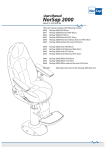
1
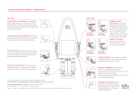
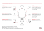
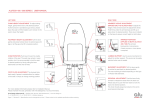
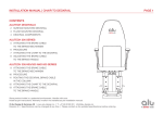
ALUTECH 300 AND 400 SERIES | USER MANUAL
LEFT SIDE
RIGHT SIDE
CHAIR HEIGHT ADJUSTMENT To adjust sitting
height, gently lift the lever until desired position.
As the function is operated by gas struts, please
leave the seat to lift the height, but/or remain in the
seat to lower the height.
ARMREST ROTATION Flip armrest backwards
at convenience if easier access or more space
is required.
FOOTREST HEIGHT ADJUSTMENT Lift the lever
gently and press footrest down to extend space for
legs or let the gas strut lift to desired position.
LUMBAR SUPPORT Use the pump mechanism
to adjust the lumbar support. The pump can be
easily reached when user is seated.
CHAIR ROTATION Push lever forward to enable
rotation of the seat. It is recommended to lock the
seat in desired position by firmly pulling the lever
backwards until the chair is fixed.
DECKRAIL MOVEMENT Lift the lever fully
to release the brake from the deck rail.
Please assure to push the lever fully down to lock
the chair in the desired location.
The chair should always be locked on the deck rail
to avoid personal damage.
FOOT PLATE ADJUSTMENT The footrest folds
back easily if space is needed either for rotation
of the seat or simply to change working position
BACKREST ADJUSTMENT Lift the lever gently
to recline the seat back to desired position.
The max reclining is limited depending on the type
of Alutech 500 delivered.
For more detailed information please refer to Installation Manual.
Please maintain the seat upholstery with mild detergents or as recommended.
© Alu Design & Services AS | Skibåsen 44, 4636 Kristiansand, Norway
www.alu-design.no | T: +47 46 82 60 00 | [email protected]
Page 1 | Revision A | Specifications can be changed at any time | Please contact us for updated specifications before ordering
TROUBLESHOOTING | ALUTECH 300 AND 400 SERIES | USER MANUAL
1 REMOVING AND REPLACING THE SEAT CUSHION
Removing the seat cushion
1. Use an Umbraco key to remove the four M6 screws
2. Recline the backrest
3. Grip the seat cushion at the front and back edge
4. Lift the front edge of the seat cushion 30 mm
5. Push the seat cushion back towards the rear of the chair
6. Lift the back edge of the seat cushion
7. Remove the seat cushion
Replacing the seat cushion
1. Recline the backrest
2. Align the seat cushion centrally on the chair
3. Push the seat cushion down and backwards
4. Use an Umbraco key to tighten the four M6 screws
3 CHAIR ROTATION To adjust the chair rotation, first
remove the seat cushion as described. The chair rotation lever
is mounted under the left side of the seat.
When the chair rotation lever is turned backwards the chair
rotation should lock in place. When the lever is turned forwards
the chair should rotate freely.
NOTE: The toolkit is delivered with each chair
2 DECKRAIL BRAKE To adjust the deck rail brake,
first remove the seat cushion as decribed. The deckrail brake
cable is mounted under the right side of the seat.
1
Issue: Chair cannot turn freely and is locked in a fixed position
Cause: Chair swing mechanism is too tight.
Solution: Remove Nut Lock Cap (A) as shown. Hold on to the
chair rotation lever. Loosen the M10 bolt with a 17 mm spanner,
until the chair is loose. Adjust as necessary.
DETAIL
Check the brake cable is installed as shown in Figure 2
and the installation manual pages 11 to 13. Reinstall if necessary.
Note: Assembly shown without chair in DETAIL image.
2
Issue: Chair cannot be moved on the deckrail
Cause: Deckrail brake will not disengage from the deckrail.
Solution: Lift the lever fully. Tighten the nuts on the cable using
the 10mm spanner until the chair can be moved on the deckrail.
Issue: Chair will not lock on the deckrail
Cause: Deckrail brake will not engage with the deckrail.
Solution: Lower the lever fully. Loosen the nuts on the cable
using the 10mm spanner until the chair locks on the deckrail.
Issue: Chair turns freely on the column and cannot be locked
in a fixed position
Cause: Chair swing mechanism is too loose.
Solution: Remove Nut Lock Cap (A) as shown. Hold on
to the chair rotation lever (B). Tighten the M10 bolt with a 17 mm
spanner until the chair is no longer loose. Adjust as necessary.
A
B
CORRECT - ROUTING BRAKE CABLE
NOTE: Do not route the brake cable under other cables!
© Alu Design & Services AS | Skibåsen 44, 4636 Kristiansand, Norway
www.alu-design.no | T: +47 46 82 60 00 | [email protected]
Page 2 | Revision A | Specifications can be changed at any time | Please contact us for updated specifications before ordering
2
3
3