1
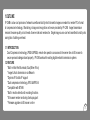
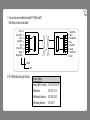
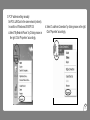
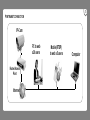
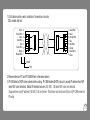
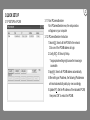
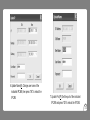
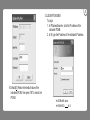
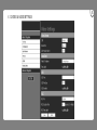
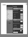
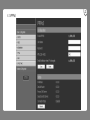
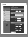
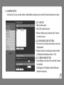
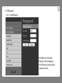
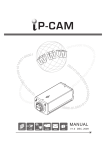
IP Infrared Color Camera Manual 2009 JUL. Ver 1.0 1/3”CCD 28 LEDS 40 M DC12V LAN RJ45 www. Cautions 1. Read this user manual before use. 2. Keep this user manual accessible. 3. Follow instruction 4. Keep this unit away from cleanser. 5. Keep this unit dry in ventilation. 6. Give way to ventilation outlet. 7. Power cord must be fixed properly. 8. To avoid damage, unit must not be stuffed or be splashed with something. 9. Do not repair this unit on your own. 10. Please contact local dealer for the following condition: a. Power cord damaged. b. Showered unit. c. Failure in operation. d. Unit dropped or cabinet damaged. 11. Repairing components must be approved by original manufacturer. 12. Ground wire of outdoor image source must be well connected to the ground to prevent from thunder attack. 13. Power cord and outdoor image source cable should be detached in case of thunder attack. Warning Only qualified engineer can detach the cover. There is nothing inside for end users. Cover must not be removed in case of power on. Content 1 1.OUTLINE 1 1.1 INTRODUCTION 1 1.2 FEATURE 2 1.3 SPECIFICATION 4 1.4 ACCESSORY 4 1.5 SYSTEM REQUIREMENT 4 2.INSTALLATION 4 2.1 CABLING 2.2 ETHERNET FRAMEWORK & CONNECTION 5 12 3.QUICK SETUP 12 3.1 IP SETUP 14 3.2 LOGIN ON IE 15 3.3 INSTRUCTION & LIVE VIEW 16 4.OPERATION 16 4.1 SYSTEM SETUP 16 4.1.1 STATUS 18 4.1.2 VIDEO SETTINGS 201 4.1.3 NETWORKING 4.1.4 PPPoE 4.1.5 DDNS 4.1.6 DATE&TIME 4.2 ADVANCE CONFIGURATION 4.2.1 MAINTENANCE 4.2.2 AFMINISTRATOR 4.2.3 MANAGEMENT 4.2.4 STMP/E-MAIL 4.2.5 FTP SETTING 4.2.6 ALARM EVENT 4.2.7 SPECIAL SETTING 5.USER GUIDE of AVPlayer 5.1 THE MAIN FUNCTION OF AVPlayer 5.2 SYSTEM REQUIREMENTS 5.3 SYSTEM INSTALLATION 5.4 USER INTERFAEC 22 24 26 28 28 29 30 31 33 34 35 36 36 36 36 36 1.OUTLINE IP-CAM is a low cost provision of network surveillance facility which transmits images on network to remote PC in format of compression technology. Monitoring, storage and recognition on line are provided by IP-CAM. Image transmission remains the same quality on both ends of server site and remote site . Single image source can he transmitted to multi - ports saving lots of cabling overhead. 1.1 INTRODUCTION Dual Compression technology JPEG & MPEG4, remote site operator can access to the server site via IE browser to secure personal safeguard and property. IP-CAM works with existing digital network transmission system. 1.2 FEATURE *Bulit-in Infra-Red Illuminator, 0 Lux(When IR on) *Image & Audio transmission via Network *Dynamic IP & static IP support *Dual compression technology JPEG & MPEG-4 *Compatible with BT.656 *Built in motion detection & recording functions *IE browser remote monitoring & setup support *Firmware upgrade via IE browser on line .1. .2. 1.3 Specification Image Input Format Lens Image Format Resolution/Frame Rate Digital BT.656 Format, 27MHz Board Lens MPEG4 / JPEG VGA:640 × 480 / 30 QVGA:320 × 240 / 30 Network Protocol TCP/UDP/IP,DHCP,SMTP,HTTP NTP, DDNS, FTP, TFTP, ARP, nPn, PPPoE, RTSP Compression Format MPEG-4 video stream with 1way PCM audio Record Format MPEG-4 video stream with 1way PCM audio Motion Detection IE. Brower Image Motion Detection Internet Explorer 5.٠ or above IPCAM Network Setup Camera Setting:Brightness、Contrast、Sharpness、Mirror Network Setting: IP Configure、PPPoE、DDNS Image Setting:Resolution、Frame Rate、Compression Rate、 P/I Rate、CMOS Frequency Firmware Update Online INPUT Infra-Red Distance LUX Wavelength Operation Temperature Size(W × H × L) Weight DC12V JACK for power、RJ-45 Network Port 40M 0 LUX –(IR ON) ON 850 nm - 5° C ~ +60°C 80(W)x84.6(H)x178mm(L) About 600g .3. .4. 1.4 ACCESSORY: 1. IP-CAM 2. Installation Guide CD 1.5 SYSTEM REQUIREMENT Pentium4 or above Windows 2000/XP/VISTA OS Protocol comply to 802.11 or ADSL network Microsoft Internet Explorer 5.٠ or above 2.INSTALLATION 2.1 CABLING 1. Power input(DC12V DC JACK) DC12V Input for IP Camera, Please make sure that the power input is DC12V before plugging the power to IP CAM. Un-normal Power input may cause the camera damaged. 2.Plug in Ethernet Cable Plug the cable in the Ethernet port with “LAN” mark for Ethernet connection. Ethernet Port Power Input 2.2 ETHERNET FRAMEWORK & CONNECTION PC TO IP-CAM CONNECTION RJ45 Cat5 Cable .5. .6. 1. Use a cross-over cable to connect IP-CAM and PC. Definition of cross-over cable: Brown Brown/White Green Blue/White Blue Green/White Orange Orange/White 8 7 6 5 4 3 2 1 1 2 3 4 5 6 7 8 COLOR PIN# 2. IP-CAM default setup as follows: Network Status Enternet MAC Address LAN Address LAN Netmask Address LAN Getway Address 00-16-55-00-00-3F 192.168.1.126 255.255.255.0 192.168.1.1 Green/White Green Orange/White Blue Blue/White Orange Brown/White Brown 3. PC IP address setting manually: Set PC & LAN Card in the same network (intranet). In condition of Windowns-2000/XP OS: a.Select “My Network Places” by Clicking mouse on the right. Click “Properties” accordingly. b. Select “Local Area Connection” by clicking mouse on the right. Click “Properties” accordingly. .7. .8. c.Select “TCP/IP” and click “Properties.” d.Select “Use the following IP address” to input IP address, Subnet mask and Default gateway. Click ”OK” accordingly. 4. Follow the following procedure to make sure IP address correct. a. Click “Start” “Run” and input “cmd” Click “OK”. b.Enter DOS and input “ipconfig”. Click “enter” to inspect IP address, Subnet mask and Default gateway. .9. .10. ★INTRANET CONNECTION IP-Cam PC to web x20 users Router/Access Point Internet Mobile(RTSP) to web x 5 users Computer 1.Cat 5 cable must be used in condition of connection via router, DSL modem and hub. Brown Brown/White Green Blue/White Blue Green/White Orange Orange/White 8 7 6 5 4 3 2 1 1 2 3 4 5 6 7 8 Green/White Green Orange/White Blue Blue/White Orange Brown/White Brown COLOR PIN# 2.Please make sure PC and IP CAMERA are in the same domain. 3.IP-CAM detects DHCP when system starts working. IP-CAM Enables DHCP protocol to accept IP address from NAT when NAT router detected. Default IP address becomes 192.168.1.126 when NAT router not detected. Suppose there is an IP address 192.168.1.126 on internet. This device must be turned off prior to IP-CAM renew the IP setup. .11. 3.QUICK SETUP 3.1 IP SETUP for IPCAM .12. 3.1.1 Run IPCameraSearcher Run IPCameraSearcher.exe, the setup window will appear on your computer 3.1.2 IPCameraSearcher Instruction 1.Search(S): Search all the IPCAM in the network. Click one of the IPCAM address to login. 2.Config IE(C): IE Security Setup. * Inappropriate setting might cause the browsing in accessible. 3.Apply(A): Search all IPCAM address automatically. 4.After setting an IP address, the following IP addresses will each automatically add up by one accordingly. 5.Update IP(I): Set the IP address of the indicated IPCAM, then press “OK” to reboot the IPCAM. 6.Update Name ( N ) : Change user name of the indicated IPCAM, then press “OK” to reboot the IPCAM. 7.Update Port ( P ) : Set the port of the indicated IPCAM and press “OK”to reboot the IPCAM. .13. .14. 3.2 LOGIN IPCAM ON IE To Login: 1. In IPCameraSearcher, click the IP address of the indicated IPCAM. 2. In IE, type the IP address of the indicated IP address. 8.Default (D) : Restore the default value of the indicated IPCAM, then press “OK” to reboot the IPCAM. ★USERNAME: admin ★PASSWORD: (N/A) 3.3 INSTRUCTION & LIVE VIEW of IPCAM Images pop out upon system login. 1. PLAY/STOP:Play/Stop Picture. 2. REC:Record the file in AV format. (Refer to 4.1.2 Video & Audio Settings to customize the file saving path.) 3. SNAPSHOT:Snapshot the picture on screen in a JPG file. (Refer to 4.1.2 Video & Audio Settings to customize a path to save JPG file.) If the path is ending by a “\”, it is a directory path. If the path is ending without a “\”, the path will link to a prefixed file name. 4. SETUP:Set system value. For further value setup, please refer toSystem Setup. 5. The Language displayed is assigned by the system(IP address.) 6. CMOS Control ˙MIR:Images reversal from left to right. ˙Brightness:Adjust the brightness. ˙Contrast: Tuning up and down the contrast. ˙Sharpness: Adjust the clearness of images. 7. By clicking the picture, the picture size can be adjusted by the size of browsing window. .15. .16. 4.OPERATION 4.1SYSTEM SETUP 4.1.1 STATUS 4.1.1.1 SYSTEM INFORMATION ˙Firmware Current Version: By updating the firmware, more functions will be attached to the program. 4.1.1.2 NETWORK STATUS ˙Ethernet MAC Address: MAC address of the IPCAM. ˙LAN IP Address: IP address of the IPCAM. ˙LAN Netmask Address: LAN net-mask address of the IPCAM. ˙LAN Gateway Address: LAN gateway address of the IPCAM. ˙DHCP State: Dynamic Host Configuration Protocol. When using static IP, the status will show“Disable ”the opposite will be “Enabled.” 4.1.1.3 CAMERA INFORMATION ˙Camera Type:Mode of Camera ˙Total Live-View Users: Total number of live-view users. Maximum user on-line is up to 20. 4.1.1.4 OCX INFORMATION ˙OCX Current Version:Current OCX version ˙OCX Path:The path accesses to OCX .17. .18. 4.1.2 VIDEO & AUDIO SETTINGS 4.1.2.1 VIDEO SETTINGS ˙CBR:Set the Constant Bit Rate of Video ˙Resolution:Picture resolution. QVGA and VGA provided. ˙Limit Frame Rate to: Frame rate transmitting per second is defined by the internet connection speed. Higher value brings smoother picture performance. 4.1.2.2 SNAP SHOT ˙Path & File Namer: Set the path to save still picture taken by snapshot. ˙If the path is ending by a “\”, it is a directory path. ˙If the path is ending without a “\”, the path will link to a prefixed file name. ˙Time Label:Enable or disable Time Label function. 4.1.2.3 OSD ˙OSD Text: Text showing on top of the picture. Maximum byte: 32. ˙OSD Font size: Size of the font. ˙OSD Enabled: Enable or disable OSD. 4.1.2.4 REC ˙REC File: Set the path to save recorded picture. ˙If the path is ending by a “\”, it is a directory path. ˙If the path is ending without a “\”, the path will link to a prefixed file name. ˙REC Duration Time:Time duration of recording. ˙REC Time Label: Enable or disable REC Time Label. ˙REC File Time Label: Enable or disable REC File Time Label. .19. .20. 4.1.3 NetWorking 4.1.3.1 IP Address Configuration ˙There are two ways to set the IP address : ˙Obtain IP address via DHCP: Obtain IP address via Dynamic Host Configuration Protocol. ˙Use the following IP Address: Set the static IP address manually. 4.1.3.2 DNS configuration ˙Two DNS IP addresses are allowed within this model. ˙Primary DNS Server: Primary DNS IP address. ˙Secondary DNS Server: Secondary DNS IP address. 4.1.3.3 HTTP ˙Prefixed port: 80 ˙If the port is to be changed, the IP address should be changed accordingly. Ex: Original IP address is 192.168.1.126, prefixed port is 80. If the port is changed to 1000, the IP address should become: 192.168.1.126:1000. .21. .22. 4.1.4 PPPoE 4.1.4.1 PPPoE CONFIGURATION ˙ Enable PPPoE:Enable or disable PPPoE. ˙User Name:Insert the user name from by ISP provider. ˙Password: Insert password from ISP provider. ˙MTU (128~1492): Maximum Transmission Unit, the largest packet that can pass onwards in communication protocol, is calculated in bytes of the size. MTU is usually set in 1500 bytes for transmission. If the MTU packets are too large, it will block up a slow interface for some time, increasing the lag on other packets. Reducing the packet size will help the smoothness of transmission. Prefixed size is 1492. ˙Email Notification when IP is changed: SMTP should be preset before using this function (Refer to 5.4 SMTP Settings.) 4.1.4.2 STATUS ˙By clicking “Refresh,” the IP status from ISP provider will be displayed. .23. .24. 4.1.5 DDNS Signing up at DynDNS, PeanutHull, or perfecteyes before setting DDNS is required. 4.1.5.1DYNAMIC DNS ˙Choose Server: Choose the DDNS server that provided by DynDNS, PeanutHull, and perfecteyes. ˙DNS Account: Account number provided by DDNS server, ex. test. dyndns.org. ˙User Name: Account user name. ˙Password: Account password. ˙Manual_Update: Update manually the IP address of current IPCAM to indicated DDNS Server. ˙Status: Insert the response from the DDNS server. ˙Save: Save above mentioned setting. ˙Reset: Reset all settings. .25. .26. 4.1.6 DATE & TIME 4.1.6.1 CURRENT SERVER TIME ˙Show current time at the IPCAM. 4.1.6.2 Time Zone ˙Choose the time zone where the IPCAM is at. 4.1.6.3 TIME MODE ˙When network is functioning, the time can be set according to the server. 4.1.6.4 UP DATE SERVER TIME ˙Time update can be done in this section either automatically for the IPCAM current time or manually for the new time. .27. .28. 4.2 ADVANCE CONFIGURATION 4.2.1MAINTENANCE 4.2.1.1 MAINTAIN SERVER ˙Restart:Restart the IPCAM. ˙Restore: Restore all settings except IP address. ˙Default: Restore all settings. 4.2.1.2 UPGRADE SERVER ˙Click “browse” and choose .IMG FIRMWARE FILE, Click “upgrade” to upgrade the firmware. Once the process is completed, click “Restore” to confirm the upgrading. 4.2.2 ADMINISTRATOR In this section, the user can add, delete, enable/disable anonymous user, and set the camera (video server) name. 4.2.2.1 USER LIST ˙Add or remove users. ˙Add: Click to add new users. ˙Remove: Select a user name then click “remove” to remove the user. 4.2.2.2 ANONYMOUS USER SETTINGS ˙Yes: Users can view the picture without user name and password. ˙Maximum number of simultaneous viewers limited to: Maximum simultaneous viewer is 1-20. 4.2.2.3 CAMERA NAME SETTING ˙Camera Name can be set with a name that is easier to remember. It will appear on IP address list when IPCamera Searcher is scanning. .29. .30. 4.2.3 Management 4.2.3.1 Change Password ˙User Name: Insert user name. ˙Password: Insert new password. ˙Confirm Password: Insert again the password to confirm. 4.2.4 SMTP (E-Mail) 4.2.4.1 SMTP Server Settings .31. .32. ˙ Mail Server:Insert IP address of SMTP server. For example, the mail box is GMAIL, then insert the mail server as smtp.gamil.com ˙From E-mail Address:Set the E-mail address of sender. Please kindly note the sender's mail box should be the same with the mail server's. For example, if the mail server is GMAIL, then the sender's mail box should be the GMAIL mail box. ˙To E-mail Address: Set the e-mail address of receiver. It will send email to this box when a trigger event occurs. ˙Authentication: If your mail box needs the authentication, please select YES. ˙User Name: User name of E-mail sender ˙Password: Password of the email address. ˙Send a test e-mail with SMTP server: Test if the E-mail settings are correct. Press “test,” you will receive the mail which subject is “This is a test message from IP address←the address of the mail server.” 4.2.5 FTP 4.2.5.1 FTP SETTINGS ˙FTP Server: Insert address of FTP Server. ˙User Name: Insert user name. ˙Password: Insert password. ˙FTP Command Port: insert FTP command port . ˙Path & File Name: Insert the path to save file name. ˙If the path is ending by a “\”, it is a directory path. ˙If the path is ending without a “\”, the path will link to a prefixed file name .33. .34. 4.2.6 ALARM EVENT 4.2.6.1 EMBEDDED MOTION DETECTION SETTING ˙Begin: Total 16 detection regions, click “begin” to edit the setting. ˙Edit Region: Under edit mode, define detection region. ˙Remove Region: Under edit mode, remove defined detection region(s). ˙End Edit: Finish editing. ˙Sensitivity: Set sensitivity of motion detection. ˙Motion Detection Enabled: Enable or disable motion detection. 4.2.6.2 Alarm Event ˙No event: the system will not be triggered. ˙Upload the recorded files to an FTP Server (FTP should be set firstly.) 4.2.7 SPECIAL SETTING 4.2.7.1 VIDEO ADVANCE SETTING ˙Compression: Select video compression. ˙P/I Ratio ( P Frame ; I Frame ) : Ratio of P frame and I frame. ˙Higher number results in smaller transmission size and duller picture. ˙ CMOS Frequency Setting: 60HZ/NTSC,50HZ/PAL Slow Shutter: Adjust to OFF、1/2 Frame、1/4 Frame. Adjust the option, enhance light into camera when at night or low light. But will lower the frame rate 4.2.7.2 RGB ˙Some old versions of display card do not support YUV display. RGB display is optional under this circumstance. CPU usage will be increased slightly while RGB display is operating. ˙Use RGB: Enable or disable RGB display. .35. .36. 5. USER GUIDE of AVPlayBack This software AVPlayBack can play the recorded files with an *.av extension and also can convert an *av file to an *.avi file 5.1 THE MAIN FUNCTION OF AVPlayBack ˙Play the recorded file with an *. av extension . ˙Supports the file conversion from *.av to *.avi. 5.2 SYSTEM REQUIREMENTS Operating System Windows 2000(SP4)、Windows XP or later DirectX DirectX 7.0 version or above CPU More than 1.5 Ghz clock Memory 512MB above 5.3 SYSTEM INSTALLATION Perform the intallation with the enclosed AVPlayBack Disc and follow the on-screen instructions to complete the installation process . 5.4 USER INTERFACE Play Frame OpenFile:Open the *.av recorded file. File information:Location of the File Path and Total Time for the video length Play Control:Fast Reverse、Reverse Play、 Pause、Play、Fast Forward Fast Reverse/Forward: 2X、4X、8X、16X、32X Snapshot:one click can capture one JPG image. Volume Control: Adjust or mute the volume. Open File File information Play Control Volume Control Snapshot .37. .38. ˙ Setting:Specify the path to save the snapshot image. ˙Snapshot Path:Specify the path to save the snapshot image. ˙OpenFile:Open the *.av recorded file. ˙ Fast Reverse:2X、4X、8X、16X、32X ˙Reverse Play ˙Play ˙Pause ˙Fast Forward:2X、4X、8X、16X、32X ˙Snapshot:Click the “Snapshot” to capture JPG images and one click for one image. Language:You can choose the language .39.