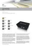
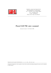
1
TC65 Lite
GPRS class 12
GSM modem
USER
MANUAL
GSM модем iRZ TC65 Lite
User Manual
Contents
Safety Requirements ..................................................................................................................................................... 3
1.
General Information ............................................................................................................................................. 4
1.1.
Purpose of the Device ................................................................................................................................. 4
1.2.
Configuration.............................................................................................................................................. 4
1.3.
Parameters .................................................................................................................................................. 4
1.4.
Exterior Appearance ................................................................................................................................... 6
1.5.
Interfaces .................................................................................................................................................... 7
1.6.
Modem Status Indication........................................................................................................................... 10
2.
Connection, Setting Up and Control ................................................................................................................... 11
2.1.
Functional Diagram................................................................................................................................... 11
2.2.
Connection, Operation Mode..................................................................................................................... 11
2.3.
GPRS Setting Up ...................................................................................................................................... 12
2.4.
Control, Restarting and Power Off............................................................................................................. 12
2.5.
Menu Mode .............................................................................................................................................. 13
2.6.
Programming Mode .................................................................................................................................. 15
3.
Emergency Situations......................................................................................................................................... 19
3.1.
Emergency 1 (input power supply invalid)................................................................................................. 19
3.2.
Emergency 2 (module power supply invalid) ............................................................................................. 19
3.3.
Emergency 3 (GSM module not started).................................................................................................... 19
3.4.
Emergency 4 (COM port not available) ..................................................................................................... 19
2
GSM модем iRZ TC65 Lite
User Manual
Safety Requirements
Restrictions for the usage of the device in the vicinity of other electronic devices:
· turn off the modem in hospitals or in the vicinity of medical equipment (e.g.
cardiostimulators, hearing aids). It can cause interference for medical equipment;
· turn off the terminal in aircrafts. Take measures against accidental activation;
· turn off the modem in the vicinity of gas-filling stations, chemical enterprises, blasting
work places. It can cause interference to technical devices;
· at a short range the modem may cause harmful interference to TV and radio receivers.
Prevent the modem from dust and moisture.
Improper use deprives you of all warranty claims.
3
GSM модем iRZ TC65 Lite
User Manual
1. General Information
1.1. Purpose of the Device
The GSM modem iRZ TC65 Lite is an industrial GSM modem designed for reception and
transmission of data via the GSM channel (GPRS class 12). Due to the embedded TCP/IP suit, and
the support of the open Java platform, in is easily integrated in many M2M solutions: mobile
Internet access, telemetry, wireless data collection from sensors, remote viewing, control and
signaling.
The control is performed by means of standard AT-commands. The terminal is equipped with a
LED indicator to track the connection status.
1.2. Configuration
Complete set of the GSM modem iRZ TC65 Lite:
· terminal TC65 Lite,
· label,
· factory box.
1.3. Parameters
Basic parameters:
· frequency ranges: GSM 850/900/1800/1900 MHz;
· power output:
o 2W (class 4 for EGSM850/900),
o 1W (class 1 for GSM1800/1900);
· GPRS class 12;
· MC class B;
· CSD up to 14.4 kbps;
· USSD;
· SMS: MT, MO, CB, Text and PDU modes;
· fax group 3: class 1.
Parameters of the open software platform:
· processor ARM7;
· memory: 400 Kb (RAM), 1.7 Mb (Flash);
· economy power supply mode;
· control of TCP/IP suits by means of AT commands;
Java ™ parameters:
· CLDC 1.1 Hl;
· J2ME™ with IMP 2.0 support;
· Secure data transmission with HTTPS and PKI support;
· TCP, UDP, HTTP, FTP, SMTP, POP3 support;
· remote update of applications (OTAP).
4
GSM модем iRZ TC65 Lite
User Manual
Electric power supply:
· power supply voltage 9 to 27 V;
· absorbed current:
o with power supply voltage +12 V – 400mA;
o with power supply voltage +24 V – 200mA.
Physical parameters:
· size, max 70х74х33 mm;
· weight, max 100 g.;
· operating-temperature range -30°С to +60°С.
Interfaces:
· DB9 RS-232,
· USB-B USB 2.0,
· FME antenna connector,
· RJ11 power supply.
5
GSM модем iRZ TC65 Lite
User Manual
1.4. Exterior Appearance
The modem TC65 Lite is a compact device designed in lightweight plastic housing. The exterior
appearance is represented on Fig.2.4.1 and Fig.2.4.2.
2
3
1
4
Fig.2.4.1 Front view
6
5
7
Fig.2.4.2 Back view
On the figures 2.4.1 and 2.4.2 the digits signify the following:
1. USB connector type B for data cable connection,
2. LED indicator of status (green) and emergency (red),
3. SIM card tray extractor,
4. SIM card tray,
5. DB9 (RS232) connector for data cable connection,
6. RJ11 connector for power supply connection,
7. FME connector for GSM antenna connection.
6
GSM модем iRZ TC65 Lite
User Manual
1.5. Interfaces
1.5.1. Connector DB9 for Data Cable Connection
The connector is used for connection to the control device, exchange protocol RS232.
5
4
9
3
2
8
Table 2.5.1 Purpose of the connector pins.
Signal
Direction
Contact
1
DCD
Modem-PC
2
RXD
Modem-PC
3
TXD
PC-Modem
4
DTR
PC-Modem
5
GND
general
6
DSR
Modem-PC
7
RTS
PC-Modem
8
CTS
Modem-PC
9
RI
Modem-PC
7
1
6
Purpose
Availability of carrier wave
Data reception
Data transmission
Availability of data reception
System housing
Availability of data
Request for transmission
Availability of transmission
Call signal
7
GSM модем iRZ TC65 Lite
User Manual
1.5.2. Connector RJ11 for Power Supply Connection
The connector is used for connection of power.
6
5
4
3
2
1
Table 2.5.2 Purpose of the power supply connector pins.
Contact
Signal
Purpose
1
GND
system housing
2
not used
3
not used
4
not used
5
not used
6
+ 12V
Positive pole of DC supply voltage.
8
GSM модем iRZ TC65 Lite
User Manual
1.5.3.
USB Connector Type B for Data Cable Connection
The connector is used to connect to the control device. The USB port does not have priority over
the COM port (the COM port becomes deactivated).
2
1
3
4
Table 2.5.3 Purpose of the USB connector pins.
Contact
Signal
Purpose
1
V BUS
+5 V (is used as input to define the USB connection)
2
D−
Data transmission
3
D+
Data transmission
4
GND
System housing
9
GSM модем iRZ TC65 Lite
User Manual
1.6. Modem Status Indication
Two LEDs are used to indicate the operation mode or any emergency situation.
Table 2.6.1 Status indication (green LED)
Conventional displaying of
Operation mode
Indication Mode
indication
Turned off
Modem is turned off or there is an
●
emergency situation
600 ms on / 600 ms off
○○○○○●●●●●
Modem is not registered in the network
75 ms on / 3 s off
○●●●●●●●●●
Modem is registered in the network
GPRS connection is installed
75 ms on / 75 ms off / 75
○●○●●●●●●●●●
ms on / 3 s off
500 ms on / 50 ms off
○○○○○●
Data transmission is underway
Modem is in power standby mode, alarm
250 ms on / 10 s off
○○○●●●●●●●●●●
clock mode.
250 ms on / 250 ms off
○○○●●●
Programming mode, menu mode
Table 2.6.2 Emergency situation indication (red LED)
Conventional displaying of
Indication Mode
indication
Turned on continuously
○
0.5 s on / 0.5 s off
○○○○○●●●●●
0.25 s on / 0.25 s off /
○○○●●●○○○●●●●●●●
0.25 s on / 1 s off
0.25 s on / 0.25 s off /
0.25 s on / 0.5 s off / 0.25 ○○○●●●○○○●●●○○○●●●●●●●
s on / 1 s off
For description of emergencies see Section 4 (page14)
10
Emergency description
Input voltage invalid
Power supply of the module invalid
GSM module not started
COM port unavailable
GSM модем iRZ TC65 Lite
User Manual
2.
Connection, Setting Up and Control
2.1. Functional Diagram
Interface converter
TL UART/RS232
RS232
DTR
UART
DB9
UART
UART
UART1
USB
D+, D-
USB
GSM module
UART0
SIM
SIM card
The functional diagram of the modem is represented on Fig.2.1.
Microcontroller
ON/OFF
Power converter
Status
RJ11
Emerge
2.2. Connection, Operation Mode
The application field of the modem can be divided into two nominal parts: personal computer
connection for Internet access and industrial use.
In both cases the connection sequence is the same.
Before feeding the power supply you need to install the SIM card in the modem (SIM card must
be enabled). To do this, you need:
· to extract the SIM tray by presssing the SIM tray extract button (Fig.2.4.1);
· to install the SIM card in the SIM tray;
· to insert the SIM tray into the modem.
No strong physical efforts must be applied while installing the SIM card.
Connect the GSM antenna and the commutation cable (RS232 or USB) to the antenna connector
(Fig.2.4.2). Thereupon you need to feed power supply to the modem through the connector RJ11
(Fig.2.4.1).
Note: GSM antenna, commutation cables and electrical power unit are not included in the
complete set configuration.
After the power supply feeding, the operating microcontroller analyses the availability of the
SIM tray. With the SIM tray available, the modem jumps to the operation mode: checks the input
voltage, commutates the UART0 pins of the GSM module to the external connector DB9, UART1
pins to the operating microcontroller, activates the GSM module. Then the registration proceeds, the
“Status” LED flashes frequently. After the registration is completed, the indicator flashes less
frequently (Table 2.6.1). In this mode the GSM module controls the flashing.
11
GSM модем iRZ TC65 Lite
User Manual
2.3. GPRS Setting Up
Connection and setting up of the modem for the Internet access from a personal computer is
carried out as that from a standard modem. If the USB interface is used, you need to install the
driver. The necessary driver can be downloaded on the manufacturer’s site (www.radiofid.ru). In
case of any difficulties refer to the guidelines on the manufacturer’s site, the Support section.
For industrial applications the modem control is performed by standard AT commands.
2.4. Control, Restarting and Power Off
The modem is controlled by standard AT commands.
The modem can be restarted in the following ways:
· by eight jumpings of the DTR line of the COM port into passive state (DTR < -2V),
duration of pulses and the pauses between the pulses must lie within the range 100-500
ms;
· by issue of a control command by the GSM module via UART1 (time rate 115200 bps,
8-N-1) to the operating microcontroller (operation mode). The command format:
@MRST[XX]<CR>, where [XX] is the number of minutes
in hexadecimal
representation (255 max), in which the module must be started – jumping to the
operation mode. If [XX] = 0, it should not be started. If the command is accepted
successfully, the response is “OK”, otherwise it is “ERROR”. The command is
completed with the code <CR> (‘\r’ or 0x0D in hexadecimal representation). Installation
of blockage or enabling for transition to the power standby mode in the menu mode does
not affect this command’s operation. During the issue of this command, the operating
microcontroller is expecting for the module’s deactivation (analysis of the PWR_IND
and VEXT pins) and starts it in a specified time period.
· by restarting in a specified time period (WD interval, disabled on default), setting up is
carried out in the menu mode;
· by temporary power-off.
The modem can be disabled using the following ways:
· by program method, using the AT commands (transition to the power standby mode);
· power supply disconnection.
When disabled by AT commands, the modem jumps to the power standby mode (minimum
consumption). Escaping from the power standby mode is made via the DTR line of the COM port or
upon the GSM module’s activation by the alarm clock.
12
GSM модем iRZ TC65 Lite
User Manual
2.5. Menu Mode
The menu mode is designed to change the modem parameters and view the statistics. In this
mode the GSM module power supply is disconnected, after the exit it is started automatically. You
can jump to the menu mode from the operation mode by extracting the SIM tray. Before jumping
into the menu mode, connect the modem to the computer through the connector DB9, start Hyper
Terminal (time rate is 115200 bpc, 8-N-1) or a similar program.
If you have entered the menu mode successfully, the LED indicator will flash frequently (see
Table 2.6.1), the main menu will be displayed in Hyper Terminal:
Menu_mode:
Variant XX
<P1> View statistics
<P2> WD interval = XXX hh (or “OFF”)
<P3> 'AT' control = ХХХ min (or “OFF”)
<P4> Sleep mode (Power Standby) = OFF (or “ON”)
<PC> Power control
<PR> Clear statistic,
where Variant XX is the weaving version.
The characters <…> signify the control commands. Input of the command gets underway after
clicking “Enter”. In case of incorrect input, “ERROR” is indicated. There is no difference between
the entered uppercase and lowercase characters.
After input of the command “P1” you jump to the statistics viewing menu:
Power_Modem = XX…X
Bad_Power_Modem = XX…X
Power_Module = XX…X
Bad_Power_Module = XX…X
Start_Module = XX…X
Bad_Start_Module = XX…X
ComPort_is_not_Running = XX…X
Deadlock_of_module = XX…X
Reset = XX…X
When the modem is used, the following situations are automatically saved:
Power_Modem – number of modem connexions,
Bad_Power_Modem – number of power supply deviations of the modem from the allowed
value,
Power_Module – number of power supply feedings to the GSM module,
Bad_Power_Module - number of power supply deviations of the GSM module from the allowed
value,
Start_Module – number of successful GSM module starts,
Bad_Start_Module – number of situations where the GSM module did not start,
ComPort_is_not_Running – number of situations: COM is not available (CTS signal),
Deadlock_of_module – number of the GSM module deadlocks,
Reset – number of restartings.
After the statistics output, you will jump to the main menu.
After input of the command “P2” you will jump to the WD menu:
13
GSM модем iRZ TC65 Lite
User Manual
WD interwal = <hour (00 - WD off, max - 255)>
<Q> Quit
WD interval =
In order to change the restarting interval, enter a number from 0 to 255 (input is after clicking
“Enter”). The restarting interval is specified in hours. If you need to disable this function, enter 0.
You should consider that after expiration of the specified time interval the modem will be restarted
unconditionally. In case of incorrect input, the modem will indicate “ERROR” and display the WD
menu again. If the restarting interval is entered successfully, or if the “Q” command is issued, you
will jump to the main menu.
After input of the “P3” command you will jump to the ‘AT’ menu:
'AT' control = <minutes (00 - off, max - 255)>
<Q> Quit
WD interval =
In order to change the deadlock check interval, enter the number from 0 to 255 (input is after
clicking “Enter”). The interval is specified in minutes. If you need to disable this function, enter 0.
In this menu the periodic check for GSM module’s deadlock is set up with the interval specified
by the user. It is arranged as follows: the operating microcontroller on UART1 of the GSM module
issues the “AT” command (time rate 115200 bps, 8-N-1), expects for response, and, depending on
whether or not the response is received, restarts the module. This function is disabled on default.
Note: Java application can take off this COM port, resulting in constant module restarting (with
this function activated).
Upon incorrect input, the modem will display “ERROR” and represent the ‘AT’ menu again. If
the restarting interval is entered successfully, or the “Q” command is issued, you will jump to the
main menu.
After input of the command “P4” – you will jump to the power standby mode menu:
Mode = (0 - off, 1 - on)
<Q> Quit
Mode =
In order to change it, you need to enter “0” or “1” (input is after clicking “Enter”). Upon an
incorrect input, the modem will display “ERROR” and represent the AT menu again. If the restarting
interval is entered successfully, or the “Q” command is issued, you will jump to the main menu.
In this menu, the modem’s jumping to the power standby mode is blocked (OFF) or enabled
(ON). That is, upon the module’s deactivation, the operating microcontroller will start the module or
not.
After input f the “PC” command – you can view the input power supply voltage and module
power supply voltage (accuracy of measurement 5%):
P0WER Uin=12.0 Umd=3.9
where Uin is input voltage in volts, Umd is voltage on the GSM module in volts.
After the output you will jump to the main menu.
After input of the “PR” command you will jump to the statistics clearing menu:
Clear statistic?
<Yes> Yes
<Q> Quit
14
GSM модем iRZ TC65 Lite
User Manual
The collected statistics if cleared by the command “YES”. Upon an incorrect input, the modem
will display “ERROR” and represent the statistics clearing menu again. Upon successful input or
issue of the command <Q>, you will jump to the main menu.
After input of the command “M” the main menu will load again.
Exit from the menu mode occurs after installation of the SIM tray, the modem jumps to the
operation mode.
2.6. Programming Mode
The programming mode is used to change / update the software of the modem microcontroller.
The software is updated via the interface RS232 using the program “ mprog2.exe ”. You can
download the program from the manufacturer’s site.
The software can be updated only for the versions 04 and further. The version variant may be
viewed in the menu mode (refer to the User Manual).
To change the weaving, the sequence of actions is as follows:
1. Start the program “mprog2.exe”. The program window will appear (Fig.1).
Fig.1
15
GSM модем iRZ TC65 Lite
User Manual
2. Close the programs using the port to which the modem is going to be connected. Click
the “Scan” button in the program window. Select the port number of the Com port to
which the modem is going to be connected. (Fig.2)
Fig.2
3. Connect the modem (without the SIM tray) to the computer. Feed power supply to the
modem. The modem is to jump to the programming mode. Flashing of the LED
indicator (green) - 250 ms off/250 ms off.
Click “Open”. Thereupon the device model is to be displayed (Fig.3).
Fig.3
16
GSM модем iRZ TC65 Lite
User Manual
4. Select the new weaving file by clicking the “File” button. A window will appear
(Fig.4).
Fig.4
5. Select the new weaving file. Click “Open”. Upon successful loading of the file, the
program window is to display the same as on Fig. 5.
Fig.5
17
GSM модем iRZ TC65 Lite
User Manual
6. Click the “Record” button. If the weaving is changed successfully, the window is to
display the same as on Fig. 6.
Fig.6
7. Click the “Start” button. Thereupon the modem will exit from the programming mode,
the COM port will close (Fig.7).
Рис.7
8. Close the program. Insert the SIM tray into the modem.
The weaving change is completed. The modem is to jump to the operation mode.
18
GSM модем iRZ TC65 Lite
User Manual
3. Emergency Situations
To simplify the use of the modem, tracking of emergencies is provided.
3.1. Emergency 1 (input power supply invalid)
Emergency 1 arises upon deviation of the input voltage from the allowed value. In such case the
modem stops the operation: disconnects the GSM module power supply. It signals with the red LED
about the emergency situation (turned on continuously). Escaping from the emergency situation is
possible only after restoring of the input voltage.
3.2. Emergency 2 (module power supply invalid)
Emergency 2 arises in the event of deviation of the power supply voltage of the GSM module
from the allowed value. In such case the modem stops the operation: disconnects the GSM module
power supply. It signals with the red LED about the emergency situation (0.5 s on / 0.5 s off).
Escaping from the emergency situation is possible only after restoring of the power supply voltage
of the module within 10 seconds from the time when the emergency situation occurred. If the power
supply voltage of the module stays incorrect within 10 seconds (with correct input voltage), the
modem jumps to the standby mode – the module power supply is disconnected, the emergency
indication persists. Escaping from the standby mode is possible only after full disconnection of
power supply.
In case of any repeated emergency after restarting of the modem, the modem is to be repaired.
3.3. Emergency 3 (GSM module not started)
Emergency 3 occurs in the event where the GSM module is not started. Red LED signaling
about the emergency situation: 0.25 s on / 0.25 s off / 0.25 s on / 1 s off. Escaping from the
emergency situation is possible only after successful start of the GSM module. In case of 10
consecutive failed attempts to start the module (15 seconds), the modem jumps to the standby mode
– the module power supply is disconnected, the emergency indication persists. Escaping from the
standby mode is possible only with full disconnection of the power supply.
In case of any repeated emergency after restarting of the modem, the modem is to be repaired.
3.4. Emergency 4 (COM port not available)
Emergency 4 arises upon the unavailability of the COM port of the GSM module. Red LED
signaling on the occurrence of an accident: 0.25 s on / 0.25 s off / 0.25 s on / 0.25 s off / 0.25 s on / 1
s off. Escaping from the emergency situation is upon the availability of the COM port of the GSM
module. In the event of 10 consecutive failed attempts (20 seconds), the modem jumps to the
standby mode – the module power supply is disconnected, emergency indication persists.
In case of any repeated emergency after restarting of the modem, the modem is to be repaired.
19