1
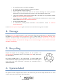
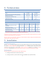
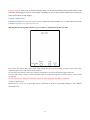
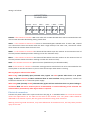
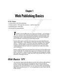
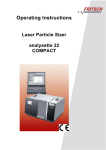
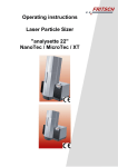
WATER TREATMENT EQUIPMENT FOR DRINKING WATER INSTALLATION, OPERATION AND MAINTENANCE USER MANUAL PLIMMER ALFA PLIMMER DELTA Machine in accordance with instructions contained in the Decree of the Ministry of Health n. 25 of 7 February 2012 (G.U.n.69 of 22/3/2012) v 2.0.18 Contents 1. Preface ....................................................................................................................................................... 4 2. Introduction to Plimmer ............................................................................................................................ 4 How a Plimmer works .......................................................................................................................... 4 What is removed by Plimmer ............................................................................................................... 5 3. Safety ......................................................................................................................................................... 5 4. Storage ...................................................................................................................................................... 6 5. Recycling .................................................................................................................................................... 6 6. System label .............................................................................................................................................. 6 7. Rules for a smooth operation .................................................................................................................... 7 9. Installation ................................................................................................................................................. 8 Installation instructions ........................................................................................................................ 8 Working modes .................................................................................................................................... 8 Piping connection ................................................................................................................................. 9 Tank connection ................................................................................................................................... 9 Electrical connection .......................................................................................................................... 10 10. Installation examples ............................................................................................................................... 11 11. Startup ..................................................................................................................................................... 12 12. Shutting off .............................................................................................................................................. 13 13. Operation ................................................................................................................................................ 13 Keyboard naming convention ............................................................................................................ 13 Settings ............................................................................................................................................... 14 Operating modes ................................................................................................................................ 14 Water missing ..................................................................................................................................... 15 Over temperature .............................................................................................................................. 15 14. Maintenance ........................................................................................................................................... 15 15. The importance of shutting off and self-‐maintenance ............................................................................ 16 16. Water and Power lack ............................................................................................................................. 16 17. Troubleshooting ...................................................................................................................................... 17 Flow is reduced .................................................................................................................................. 17 Water quality decrease ...................................................................................................................... 17 Input and output water quality is the same ....................................................................................... 18 Overtemperature shutting off ............................................................................................................ 18 18. Useful information .................................................................................................................................. 18 2 Water potabilization ........................................................................................................................... 18 How to evaluate the quality of drinkable water ................................................................................. 21 Effects of the presence of clay in the water ....................................................................................... 22 How to verify the presence of clay in the water ................................................................................ 22 How to remove clay from the water .................................................................................................. 23 How to mantain the water quality in the output tank ....................................................................... 23 19. Identification of the Manufacturer .......................................................................................................... 25 20. Declaration of conformity ....................................................................................................................... 25 21. Declaration of CE conformity .................................................................................................................. 25 22. Safety certification .................................................................................................................................. 25 23. Standard warranty: terms and conditions ............................................................................................... 26 v 2.0.18 -‐ 31/10/2013 3 1. Preface This manual has been produced by Idropan dell’Orto Depuratori srl to give Users the necessary information to operate and maintain the machine within the designed limits of occupational health and safety given compliance with local statutory regulations and the following instructions from the manufacturer. Warning: it is forbidden to remove pages, or to make corrections, deletions or modifications. Warning: this manual should be supplied with the machine. KEEP THIS MANUAL We recommend that Users keep the manual in an easily accessible place to be referred to when needed. We also would be grateful for feedback from Users – please access www.idropan.com and use our email Contact Form. This instruction manual should be kept with the utmost care and must accompany the equipment throughout its operational life. In the event of a sale of the Plimmer unit, the manual must be delivered to the new owner. If this manual is lost or damaged, you can ask for a copy by using our email Contact Form at www.idropan.com and providing the serial number of the machine that you can find on the back of the equipment. 2. Introduction to Plimmer How a Plimmer works Plimmer is an innovative system used to remove salts from water without the need for resins or membrane filters. Plimmer uses pairs of electrodes placed next to each other at a separation of 0.1 mm and enclosed in a plastic cell. The electrodes are powered to a continuous voltage of 1.5-‐1,6 Volts – a level that avoids gas production from electrolysis. During operation, an electrostatic field will be created in the cell and ions dissolved in the water to be treated will be attracted to the electrode of opposite polarity (Phase 1). The result is partial demineralization of the input water until the electrodes become fully loaded with captured ions. At this point the system will automatically short-‐circuit the electrodes (Phase 2) releasing the ions and after that will reverse the polarity and move all the captured salts to the waste drain (Phase 3) in a small amount of water (around 20% of input water). At the end of phase 3, the electrodes are regenerated and can then start a new demineralisation cycle. The whole process takes place automatically at a frequency of about one minute. 4 Please note – “Phase” not “Fase” in the following diagram What is removed by Plimmer Plimmer technology removes substances that dissociate into ions from water, including: Temporary hardness Permanent hardness Sodium chloride Sodium sulfate Nitrates Nitrites Ammonia Fe Mg Arsenic Hexavalent chromium Metals Ca (HCO3)2 Mg (HCO3)2 CaCl2 MgCl2 CaSo4 MgSO4 NaCl Na2SO4 Anion NO3 Anion NO2 NH4+ (if present in ionic form) (if present in ionic form) (if present in ionic form) 3. Safety Caution: A failure to follow these instructions may result in personal or damage to equipment. The electrical safety of this machine is guaranteed only when connected to an electrical system equipped with an effective ground connection and a circuit breaker. This safeguard is a mandatory requirement in the use of Plimmer equipment. If you are unsure of the status of the electrical system, it is essential to take professional electrical advice. The use of a Plimmer system, as well as any unit connected to the electrical system associated with aPlimmer system, requires the observance of some basic safety standards: • do not touch the system with wet or damp hands or feet; • do not connect or disconnect power cord with wet hands; 5 • • • • • • • • do not pull the power cord while unplugging; do not leave the system exposed to atmospheric agents; do not let children control the system; before doing any maintenance, switch off the system following the correct procedure explained in this manual and when the system is shut off, unplug the power cord; in the event of failure, switch off the system and do not touch. For any assistance, please contact our Technical Service Department; if the power cord is damaged, it must be replaced by the manufacturer or from another authorised and professionally-‐qualified tradesman. use only original spare parts; for maintenance, carefully follow instructions in this manual or contact our Technical Service Department. Caution: Plimmer systems require regular maintenance to maintain drinking water standards. 4. Storage Packed Plimmer units must be stored in a dry environment (free from condensation) and protected from the weather. The allowable storage temperature range is 5°-‐50°C. Even when packaged, Plimmer units should be handled carefully and considered as fragile. When you receive a Plimmer unit, it should be immediately unpacked and checked for damage. In the event of damage in transit, please contact your distributor immediately. 5. Recycling Recycle or dispose of the packaging material for this product in an environmentally responsible manner. Do not leave plastic bags, paper clips, etc. near children To prevent possible harm to the environment or human health from uncontrolled waste disposal, please separate these items from other types of waste and recycle them responsibly to promote the sustainable reuse of material resources. 6. System label Our systems can be recognized by a label on the back where you can find major details such as: serial number, securcode, model name, input power data. 6 S/N: 2013050088 Securcode: 4578 7. Rules for a smooth operation Drinking water that feeds the system must be clear, free of hazardous substances or pathogens and should not be biologically active. In this situation a standard activated carbon cartridge may be adequate to remove chlorine/chloramines and sediments thus making the water suitable to feed to Plimmer. Algae, zooplankton, rotifers, worms or other microorganisms must be removed before the water reaches the Plimmer equipment. Colloidal suspensions, clay residues, mineral and vegetable oils, surfactants, bacteria or viruses must also be completely removed before the water reaches the Plimmer equipment. In addition: • • • • maximum inlet water temperature must not exceed 35°C; minimum inlet water temperature must not be below 5°C; the Plimmer system must not be placed in areas subject to frost; the Plimmer system must be placed in a ventilated area, away from heat sources and not exposed to the direct sunlight; • input water pressure must be reduced with a pressure regulator set at 2 bars mounted after the pre-‐ filters. This pressure requirement must not be exceeded under any circumstances. • input water and electricity should not be frequently interrupted ( ie more than once a week). Should frequent interruptions occur please refer to Section 19 of this User Manual. • when the system is powered there should be no voltage drop caused by other machinery (i.e. borehole pump); • do not use water produced by a newly installed system or by a system with new filters for at least 20 minutes; • installation and maintenance must only be done by our Technical Service Department or other authorized personnel; • be sure that the voltage applied is the same as required by the label on the Plimmer system; • after downtime of more than 15 to 20 days, it is recommended that the Plimmer system be sterilized with an extra acid wash cycle and run to waste for 20-‐30 minutes; • if new piping is used for a Plimmer system, it should be flushed with fresh water for some days before completing the installation; • water pressure before the pre-‐ filter should be set between 3 and 5 bars. • before unplugging the Plimmer system, switch it off correctly (see Section 11 of this User Manual). Please note: Failure to comply with these Rules will void Warranty. 7 8. Technical data ALFA SERIES Model Alfa DW1 Alfa DW2 Maximum daily production at 25°C (litres/day) 2500/3000 * 5000/6000 * Maximum salt removal 65% - 75% 65% - 75% Average power consumption (W) 75 * 150 * Installed power (Kw) 0,40 0,62 15mm / ½” 15mm / ½” Minimum pipe diameter DELTA SERIES Model Delta SP1 Delta SP2 Delta DP1 Mini Delta DP1 Maximum daily production at 25°C (litres/day) 1800/2000 * 3600/4000 * 800/1000 * 1600/2000 * Maximum salt removal 75% - 85% * 75% - 85% * 85% - 95% * 85% - 95% * Average power consumption (W) 75 * 150 * 75* 150 * Installed power (Kw) 0,40 0,62 0,30 0,62 15mm / ½” 15mm / ½” 15mm / ½” 15mm / ½” Minimum pipe diameter * The values refer to a conductivity input of 400us. Salt removal percentage decreases with increasing conductivity of the water inlet and vary with the types of salts dissolved in it. Components of Plimmer equipment have been factory-‐tested and fulfill the legal requirements for water treatment purpose detailed in this User Manual. Plimmer systems are tested before shipping: we check electrical systems, piping and mechanical parts, system function and output water quality. 9. Installation Installation instructions Plimmer systems are simple, compact and easy to install. Before starting, be sure to have enough space for the system to avoid complications during maintenance. Use a dedicated power socket with ground connection and protected by a circuit breaker. Plimmer systems are designed to be installed in a clean environment, protected from freezing, away from heat sources, and not directly exposed to sunlight. Working modes Plimmer systems are versatile and can be used in different ways: a) Feeding a tank with electric floats (min and max) b) Feeding a tank with a pressure water level sensor (available only on specific models) 8 Plimmer systems, with a use of another electrical float, can control an external NO (normally open) or NC (normally closed) bypass valve to ensure water availability in case of any problem faced by the system (eg power interruption or high usage). Piping connection Connect the system following the diagram below. Input water pressure after the pre-‐filter must be set with a pressure regulator at a maximum of 2 bars. Warning: be sure to connect pressure regulator after the safety filter on the input line. The system has 15mm John Guest type rapid fittings for the inlet and outlet and 6mm John Guest type rapid fittings for drain and maintenance solutions. For the drain connection a 6mm-‐1/4” pigtail is supplied. Do not use a 6mm pipe longer than that. For inlet and outlet, 3 meters of 15mm flexible pipe are supplied along with 3 fittings with ½” male thread connection. For the maintenance solution connection, a 6mm 1 meter long pipe with filter is supplied. Tank connection Electrical float connection or pressure sensor connection is done by connecting clamps on the external connection box. 9 Wiring is as follows MORSETTIERA PLIMMER BABY BYPASS ALM L. MAX L. MIN L. + SNS1 - + SNS2 - BYPASS: is the contact to connect a NO or NC valve with 12 VDC solenoid which will be activated when tank level is lower than what decided by placing “ALM” float. ALM L. : is the contact to connect to an active or deactivate bypass solenoid valve. If valve is NO, I should use a float which closes the contact when the level is high instead, if the valve is NC, I should use a float which closes the contact when the level is low. MAX L. : is the contact to connect to the electrical float which stops the machine at the maximum level of the tank (contact should open when reaching or over the maximum level). MIN L. : is the contact to connect to the electrical float which starts the machine at the minimum level of the tank (contact should close when reaching or under the minimum level). SNS1: is the contact to connect to a pressure sensor (available only on selected models). SNS2: is the contact to connect to the water missing pressure switch which has to be connected after the security filter on the inlet and set to 1,2 bar to have contact open when water is missing. Warning: Bypass solenoid valve model: When using a NO (normally open) solenoid valve, bypass can also operate when there is no power supply. It will be necessary to add a mechanical float to avoid overflow. During operation, solenoid can become hot because of the continuous power supply. When using a NC (normally closed) solenoid valve, bypass will not work when there is a power leakage. A mechanical float will not be necessary but is recommended, to avoid overheating of the solenoid. The solenoid will be powered only when bypass water is required . Electrical connection Connect the power cable to the system and insert the plug in an available socket. Be sure that the outlet meets the requirements on the label on the back of the Plimmer unit. The power outlet should be dedicated to the Plimmer system, with the ground connection having a low resistance. Warning: lack of a ground connection, may cause disfunction of the Plimmer unit, and may cause personal injury to the User. 10 10. Installation examples The following diagram shows how to install a Plimmer unit with mains water input. The system components are: one or more filters, a pressure regulator and finally the Plimmer unit. The Plimmer outlet must be connected to a tank where a pump will pressurize water to the user circuit. INGRESSO ACQUA PLIMMER RIDUTTORE DI PRESS. FILTRO USCITA ACQUA OZONIZZATORE UTILIZZO ACQUA VALVOLA BYPASS SERBATOIO ATMOSFERICO If input water is from a bore, the system connection will be the same except for the required potability of the output water which should be chosen depending on input water quality and type and a tank with a pump (if not included in an existing potable water piping system). The aim of the input side of the potable water system is to remove bacteria, viruses, algae, zooplanckton, elements and all other mono-‐ or pluri-‐ cellular microorganisms, turbidity, clay, mud, colloids or any other suspension that can biologically, mechanically or chemically impact the Plimmer system. The aim of the tank with a pump is to avoid high pressure peaking or water hammer to the pressure regulator. INGRESSO ACQUA SISTEMA DI POTABILIZZAZIONE SERBATOIO ATMOSFERICO PLIMMER RIDUTTORE DI PRESS. POMPA DI RILANCIO FILTRO USCITA ACQUA OZONIZZATORE UTILIZZO ACQUA VALVOLA BYPASS 11 SERBATOIO ATMOSFERICO 11. Startup After having connected the entire system, check that the maximum input pressure after the reducer is set to 2 bars and that the input circuit piping does not contain chips or dust or any kind of installation residues (eg oil, grease, etc.). It is recommended that a temporary connection is made to the waste outlet to allow the input piping to be flushed for at least 30-‐60 minutes to remove any installation residues. Air entrapment may occur in the input circuit, so it is suggested that the input valve is partially opened for a few minutes to “bleed” the circuit prior to fully opening the input valve. After having partially opened the input valve, connect the power cord and press the switch on the side of the Plimmer unit to power on the system. A text message stating the firmware version of the Plimmer unit will appearon the display screen for 3 seconds, and then the following texts will appear: “Plimmer starting” if the tank has a level lower than MIN L. or “Plimmer waiting” if the level of the tank is between MIN L. and MAX L. If the “Plimmer waiting” message appears, allow water inflow from the input until you read the text “Plimmer starting”. Once the system is in “Plimmer starting” phase, the Plimmer unit will wash the cells to waste for 2-‐3 minutes. Then, when the system enters production phase, on the display will read “Plimmer On” and it will start filling the tank with treated water. Please check that there are no leaks and be sure to have correctly connected the maintenance solution pipe. To check if maintenance solution is connected properly, manually move MAX L. float, wait for the text “Plimmer shutting off” and check if, after 3-‐4 minutes, that maintenance solution is correctly drawn. It is important to check that liquid has been drawn and that the piping is now full of maintenance solution (if not, repeat the procedure until the pipe is full). Please verify that the right amount of maintenance solution has been selected on the device. After having totally opened the input valve, verify the flow on the outlet with a flow meter (or with a jug and a chronometer) to be sure it complies with the specifications of the system. You can use a standard 1.5 l bottle with the following filling time. Model DW1/DW2 SP1/SP2 DP1 DP1 Mini Filling time 18 s 27 s 27 s 54 s If production is lower that the nominated level, try to minimally increase input pressure and verify again. If production is higher, reduce input pressure to 1.8 bars (minimum value) and try again. Il the problem persists, please contact your local distributor. 12 Check that input pressure before the pre-‐filters is between 3 and 5 bar. 12. Shutting off If you need to switch off the system (for example for a long holiday or for maintenance to the house) it is important to follow the right procedure and not only unplug the power cord. If the display shows the text “Plimmer waiting”, you can switch off the system with the lateral switch and unplug the power cord. In all other circumstances: Push the “on – off” button and when prompted enter the user password. Default user password is : 10000. Confirm with OK button and again push the “on – off” button. When the display shows “Plimmer Off”, switch off the system and unplug the power cord. 13. Operation Keyboard naming convention Arrows up/down/left/right OK On -‐ Off Key Magnifier Gear 13 Settings To enter settings menu, press the “Gear” key and when ppted insert the user password. Default user password is: 10000. Confirm with the OK button and then press the “Gear” key again. Here is the list of all the settings: PLIMMER MAINTENANCE DO YOU WANT TO MAKE AN ACIDIC WASH ? NO With the up/down arrows you can select yes/no and confirm with OK button. The choice is to start an extra wash of the cell that will be explained later. With the up/down arrows you can select one of the 16 available levels. The higher the number, the higher the salt removal percentage. Press “OK” key to confirm. CHOOSE OUTPUT WATER QUALITY 1=LOWER 16=BEST 15 PLIMMER SAVING DATA IN PERMANENT MEMORY PLEASE WAIT Wait for the Plimmer system to save the data. Do not switch off the system during data saving. Operating modes The Plimmer system will behave differently depending on the level of the input tank: it will start production if level is lower than MIN L. and will stop when at MAX L. When starting, the system will wash the cells for about 2-‐3 minutes. The display will read ”Plimmer starting”. After that, the Plimmer unit will start producing water with cycling production phases and regeneration phases. For the DW1, SP1, DP1, DP1 Mini models, outlet flow will be discontinuous while for the DW2 and SP2 models will be continuous. When the system reaches maximum tank level (MAX L.), it will start shutting off with a specific washing cycle that lasts 4-‐5 minutes during which the desalination cells are regenerated and maintenance solution is injected. If a bypass circuit is available and water level goes below ALM level, the valve will be opened and will be closed when reaching MIN L. Meantime, the Plimmer will continue water production that will mix with untreated water. If the system runs continuously for more than 20 hours (without reaching MAX L.), the machine will automatically stop for 4 hours and maintenance solution will be injected. It is very important to check float positions in order to have at least a 2-‐3 hours working time for the system and a 4 hours period in which the system can stop for maintenance. This is very important for optimal functioning of the system. 14 Water missing The pressure level switch installed after the filter and set to 1.2 bars and is intended to open the contact when inlet pressure is lower than the set value which can be caused by a failure in the water supply or a clogging of the filter. The display will read: PLIMMER WAITING DUE TO MISSING WATER IN ….. RESTART the system will automatically recover. Waiting time is the same as the maintenance time of the system (1-‐2-‐4 hours). Over temperature In the event of overheating, the Plimmer system will automatically stop to avoid damage and will restart 15 minutes after the system has cooled. PLIMMER WAITING DUE TO OVER TEMPERATURE RESTART IN ….. When the system starts, you can read the total number of over temperature events from the system display. 14. Maintenance Plimmer systems do not require difficult maintenance procedures. During shutting off, or after 20 hours of continuous production, Plimmer systems will automatically inject maintenance solution to avoid fouling inside the cell. It is recommended to check the use of maintenance solution by the Plimmer unit on a regular basis. If the Plimmer unit is not drawing on the maintenance solution, please contact your authorized technician immediately. If you notice a performance decrease of greater than 10%, it is important to carry out an extra maintenance procedure. A maintenance procedure can be started within the settings menu (gear button) as explained in previous paragraph. It is important not to wait too much time before starting an extra maintenance procedure because if the fouling is too high it will be more difficult to revert performances to nominal values and a specific wash in an authorized center may be needed. WARNING Do not stop the system while doing the extra maintenance procedure. Stopping the system at this point may cause damage to the Plimmer unit. 15 15. The importance of shutting off and self-‐maintenance Plimmer technology offers a water recovery higher than that obtainable from reverse osmosis. This means that while Plimmer is in the regenerating phase, waste water is highly concentrated and because of this is liable to create deposits very quickly. Supersaturated water tends to create scale deposits as soon as any incrustation is present in the pipes. This is a necessary consequence of Plimmer’s water saving capability over that of other technologies. Plimmer uses a patented maintenance solution injection method keeping the solution inside the cell for defined time intervals. This injection of a mixture of citric acid and other additives help to dissolve cell fouling deposits. The same solution prevents also precipitation in the cell and in the valves. The quantity of maintenance solution used is very low, but should be adjusted based on the hardness of the incoming water. If you exceed the required quantity of maintenance solution, no problems will occur. If the required quantity of maintenance solution is not used, fouling will inevitably occur. Plimmer strongly recommends that operators regularly check “if” and “how much” maintenance solution is used. Please note that shutting off the system without following the correct maintenance procedure will lead to quick fouling. If water pressure drops, or power fails, this will lead to malfunctioning of the Plimmer system. If this occurs frequently, we recommend the installation of a small Uninterrupted Power Supply unit, and a small pressurized tank following the scheme presented in the next part of the manual. 16. Water and Power lack For correct operation of the Plimmer system, it should not have frequent interruptions to water and/or power. If this occurs, it is strongly recommended that a control be installed which will shut off the system in these circumstances. A typical controller would be a pressure switch which senses the interruption of water supply, and a relay which senses the interruption of power. Both the sensors will force a shutdown of the system that, given the installation of the protection system in the previous paragraph, may then be powered by the UPS and use water from the pressurized tank. 16 Here is the connection scheme for the protection system: Pressurized tank volume: 24 litres UPS data: 1000 VA, 10 minutes battery duration Relays: coil 220 VAC, 2 contacts NO (12V) 17. Troubleshooting Plimmer is designed to work continuously without human intervention. However, in the event of operating difficulties, the following notes may assist: Flow is reduced If water flow reduces more than 10% of nominal value, it may be that the cells are becoming dirty because of calcium and/or other substances (e.g. clay, sand, organic matter). First of all, try to do an extra maintenance procedure following the procedure explained in Section 11. If the problem is due only to hardness (calcium), this will correct the problem. Please check again that the quantity of maintenance solution being used is correct and, if necessary, gradually increase the value. If the problem persists, it may be that the input water is not compliant with the requirements for satisfactory Plimmer operation. Please contact your local reseller to find a solution to the problem. Water quality decrease If output water quality decreases, it is generally corrected by an extra maintenance procedure as explained in Section 11. If a decrease in output water quality is happening whilst there is also a flow reduction, please follow the explanation in the previous paragraph and contact your local reseller. 17 Input and output water quality is the same Please contact your local reseller. Overtemperature shutting off If the Plimmer system reaches an unacceptably high operating temperature it will automatically shut off to prevent damage. Recovery is automatic and the display will show, during power on, the number of over-‐ temperature shutdowns that have occurred to the system. Plimmer will permanently store the number of over-‐temperature shut off incidents. If over-‐temperature shutdowns occur frequently, the Plimmer unit may be installed in an unsuitable environment, or input water salinity may be too high. 18. Useful information Water potabilization Water potabilization is the removal of contaminant substances from raw water to obtain drinkable water or industrial use water. This process normally takes place at the municipal waterworks level. Bore water can be treated in a similar way by using a small scale potabilization treatment such as Plimmer. To decide the right treatment, it is important to consider several factors: • • • Bore depth and structure (quantity and position of captation slots) Soil composition; and The seasonality of water quality. Deeper bores normally offer high salinity water but more “pure”. With “pure” water we mean water without clay, algae , colloids and suspensions. Drinkable water should always belong in this category. Unfortunately, often during bore construction captation slots are added at different depths. This allows the bore to collect more superficial water which often contains clay, turbidity and algae due to insufficient natural filtration. In this situation a treatment regime is needed. Common potabilization systems include: • • Sterilization Filtration Sterilization removes all microorganisms – bacteria, multicellular organisms, algae, molds, yeasts, mucilage and viruses. Multicellular organisms, algae, molds, yeasts, mucilage and viruses are much more difficult to remove than bacteria and therefore require higher doses of sterilizing agents. There are two substances commonly used as sterilizing agents: • • Chlorine Ozone 18 Please note: UV germicidal lamps may NOT be included in this category because they almost never succeed in eliminating multicellular organisms. The sterilizing agents are strong oxidants and for this reason also affect the oxidisable substances present in the water, or rather their action is preferred against chemicals than against living organisms.. For this reason it is necessary to determine the appropriate amount of oxidant to be added to maintain a residual concentration of active oxidant suitable to achieve full sterilization AFTER the oxidation of inorganic and organic substances present. The oxidation process also acts on organic substances (non-‐living) such as humic acids present in greater measures when the well is relatively shallow. The oxidizing action often promotes the coagulation / flocculation of these substances making them easily removed by subsequent filtration. To achieve a correct sterilization is essential that: • • • • The oxidant is injected at a high turbulence point An adequate reaction time should be considered and connected to the oxidant type (i.e. ozone is more rapid than chlorine). Main dosing should not be done in a tank without stirrer. The level of active oxidant after the oxidation of the oxidable substances present is high enough Without claiming to define the optimal values but only as a guide and to indicate an order of magnitude for chlorine, it is normally acceptable to maintain a concentration of free chlorine of at least 3 ppm after 60 minutes of contact with the water to be sterilized. For ozone, a similar rule of thumb is that it is normally sufficient to maintain a dosage of 1-‐2 ppm for 10 minutes of contact of net consumption linked to the oxidable substances. Free active chlorine is defined as chlorine which reacts with an indicator (such as the DPD red indicator) without using potassium iodide. The total chlorine instead is one that reacts by generating staining with the addition of potassium iodide. The difference between the two values is therefore the combined chlorine value. Combined chlorine does NOT guarantee sterilization and therefore the above values should be measured in the absence of potassium iodide. Direct dosing in a tank without stirring or agitation should be avoided because: • • good mixing of the oxidant is essential contact time with the oxidant must be at least double the minimum time recommended Filtration means a treatment to remove particles and flakes that are suspended in the water to be treated. There are many different types of filtration: • • • Cartridge filtration Filter bed media filtration Membranes filtration Cartridge filtration is the most common filtration technology because is simple and inexpensive but requires particular attention while choosing the right model of cartridge. The first thing to check, simple but not obvious, is the length of the filter element. Historically (and for commercial reasons) two kinds of cartridges are common, very similar, but not interchangeable. The most common lengths (in inches ) are: 19 • • 9 ¾ 10 It is essential to utilize the correct length cartridge for the filter housing. The second variable to consider is the "type" of filtration. There are two filtration specifications: • • Absolute filtration (ie: no particle larger than “x” can pass through the filter) Relative filtration (ie: a % less than “y” of particles larger than “x” can pass through the filter) A relative filtration level will always be of lower efficiency (lower means that more particles will pass through ) than an absolute filtration level. For example, a 5 microns relative filter, can offer the same performance as a 10 microns absolute filter. The third variable to be evaluated is the use of activated carbon in the filter. This can be useful for several reasons such as the removal of small residues of chlorine or ozone or better removal of colloids. Filtration on a filter bed is the optimal filtration process for removal of oxidant after a sterilization process. Cartridge filtration cannot remove chlorine levels exceeding tenths of ppm and therefore the use of a filter bed becomes crucial in these cases. There are three main types of bed filters: • • • Pressure filters with a lower slotted distributor Pressure filters with baseplate and nozzles “Open Top” filters Pressure filters with a lower slotted distributor are the most common model even if not totally efficient because they can not be washed with insulated air and so over time lead to preferential patterns that compromise good working. It is advisable to check the status of the filter bed every 6 months. These filters are often filled with activated carbon to help remove chlorine, therefore it is important that backwash water contains a high value of sterilizing product (up to few dozen ppm) followed by a concurrent wash until the disappearance of the oxidizing product and any remaining turbidity. The bed of activated carbon often loses its effectiveness after 12-‐18 months of work thus requiring its replacement. It is important to consider the volume of granular activated carbon required because too small a volume may lead to a premature “pass through” of oxidant. As a general rule consider that one litre of granular activated carbon can treat 12 litres of water in one hour. Pressure filters with baseplate and nozzles are the best type of pressure filter and often their action is assisted by the injection of compressed air at the operating pressure. The oxygen thus introduced performs an oxidation of the organic substances of iron, manganese and hydrogen sulfide present enhancing the effect of sterilizing. This type of filter allows washing with air blown from the bottom nozzle which acts as a distributor and equalizer. The phase of backwashing with air smooths out the filter bed avoiding the formation of preferential pathways. 20 These filters should always be preferred if the load of substances to be removed is high and if manganese is present at the same time as oxidation. Open Top filters are a new range of equipment that in case of moderate flow (such as those related to single-‐family houses) can achieve filtration and sterilization in a single non-‐pressurized tank. They also act as a small storage tank for feeding the pressurizing pump for the Plimmer unit. The backwash is done with treated water provided by the pump that feeds the house. One of the advantages of this type of equipment is the easy and immediate verification of the state of the filter bed and, in the case of its replacement the use of a simple vacuum suction device. Membrane filtration is the technology to be used in treating surface water or groundwater from boreholes. It is based on special types of filter materials of very small porosity (0,1 to 0,005 microns) that can be constructed either in the form of sheets or in tubular form (similar to pipes in a size like “spaghetti”) The basic concept of their functioning is a frequent chemical backwash usually using chlorine. The chemical backwash oxidizes and destroys the biomass that inevitably generates on the surface of the membrane, making filtration more difficult. The backwash frequency (which occurs automatically) is about 15-‐120 minutes. This kind of filter completely removes mono and multi cellular organisms but is not a safe barrier against viruses therefore it is important to add a sterilization step. How to evaluate the quality of drinkable water Evaluating the quality of drinkable water is not easy but if the treatment process has been done correctly the quantity of microorganisms or colloids quantity in the water should be very low. In the past it was claimed a filtration test that evaluates the "clogging" power of the water in a fast and inexpensive way or the "Test of SDI" (Silt Density Index) was a satisfactory measure of water quality. This test consists of a filtration on a small flat membrane (similar to a disc of paper) that is run at constant pressure (2 bar) for a period of 15 minutes. By evaluating the productivity of the membrane (the time required to produce 500 milliliters of water) at the beginning of the test and after 15 minutes of work it becomes possible to calculate a dimensionless number that is an indicator of the total amount of suspensions and colloids present in the water. Example: Initial time is 20 seconds (to filter 0,5 liters of water). After 15 minutes it take 45 seconds SDI value is 6,667*(1-‐20/45)=3,7 SDI= 6,667* (1-‐ (initial time/final time)) • • • SDI values greater than 5 mean a poor and insufficient treatment Values between 3 and 5 recommend a tune-‐up of the process Values less than 3 are optimal This type of test is very important because it allows an advance evaluation of the possible fouling problems of a Plimmer system. 21 Effects of the presence of clay in the water Clay is a substance insoluble in acids and bases and in water is present as very fine particles (up to 0.2 microns). These particles have a strong positive superficial electrical charge and therefore tend to attach to surfaces with a negative charge. A standard mechanical filter is not a barrier able to totally remove clay which, especially in smaller size particles, can create layers totally insoluble by chemicals and able to reduce the performance of all water treatment systems. In water softeners for example clay particles accumulate near or inside the macropores present on the external surface of the resin spheres, blocking them. Since the effective exchange capacity for an exchange resin is for the most part contained in the micropores that branch in the center of beads from the macropores that act as main channels for conveying the flow and the ions, if blockages occur, capacity will drop. In systems Reverse Osmosis membranes have a strong negative surface charge, and then the clay particles accumulate on the surface of the membrane leading to either a worsening of the quality of the permeate due to a higher concentration of salts than for a mechanical occlusion of the pores of the membrane itself which then reduces its productivity. Even in Plimmer the positively charged clay particles tend to be attracted to the negatively charged electrode surface in the cell. Because of its insolubility in acids and bases often a clogging due to clay leads to an irreversible fouling. It is therefore essential to recognize and remove even a small percentage of clay in the water to be treated. How to verify the presence of clay in the water The presence of clay is detected in the most obvious cases simply by taking a sample of water and leaving it to settle for at least several hours (for example overnight). If the bottom of the container shows the presence of a deposit you should perform a simple test to understand its nature. In fact, even iron manganese and various organic substances can lead to the creation of a bottom body. Concentrating the deposit and adding an acid (hydrochloric, sulfuric, nitric, citric, acetic for example) gives two different situations: • The deposit melts leading to a clear solution even if no longer colorless (for example iron imparts a yellowish dye) • The deposit does NOT melt or dissolves only partially The same test can be realized with a small part of a dirty filter that, immersed in an acid solution, should return to the starting color if it has not filtered out clay. An SDI test is easy method to detect the presence of clay by immersing the membrane (after filtration) in an acid solution in the way described above. 22 How to remove clay from the water Small clay particles which have a high surface electric charge can be removed by coagulation and filtration. In the purifying treatment it then becomes easy to integrate the action of the sterilizing product (chlorine or ozone) with a small dosage of a salt of Iron (Ferrous or Ferric chloride or Sulphate ). The choice of the best salt is dependent upon the simultaneous presence of any organic substances that need removal (Oxidisability index or consumption of permanganate). In the presence of a high oxidisability index, the use of a ferrous salt allows the formation of free radicals that oxidize organic substances favoring their flocculation while the trivalent iron that is formed as a result of oxidation flocculates in turn, incorporating the clay present. The flakes that are formed can be easily removed by a media filter or by the same chlorine filter with active carbon. In this case, however, the useful life of the activated carbon is reduced requiring replacement more frequently. In general, the addition of a salt of iron (and more rarely of one of Aluminium which produces more colloidal and less easily filterable flakes) helps to obtain clearer water with a reduced content of organic substances and free of clay. The amount of iron salt to dose varies according to the individual case, but a possible starting value suitable for many cases it might be about 0.7-‐1 gram per cubic meter of water (expressed as metallic iron). A product available with ease that can provide excellent results is Ferrous Sulphate which reacts by creating free radicals both with ozone or with the chlorine. Caution must be taken into account for the increased consumption of oxidant to transform bivalent iron into trivalent iron How to maintain the water quality in the output tank The treated water from Plimmer is accumulated in the tank outlet which is a normal atmospheric tank and as such is subject to contamination. We strongly recommend adding a sterilization system to that tank. There are several different possibilities, such as: • • • Chlorination UV lamps inside the tank Ozonation Each of these systems has its strengths and weaknesses. Chlorination in fact is the one that provides good protection even if the pipes are long or contain deposits (possible local causes of bacterial pollution). UV lamps placed directly in the tank can be an effective method especially in tanks made of polished stainless steel as the reflection on the walls improves the effectiveness of UV. The method recommended by Plimmer, however, is ozone dosage. The amount of ozone needed to maintain the quality of water in a reservoir is very small and is around 0.05 / 0.1 grams per hour per 1000 liters. An ozone generator of this size is a small, low power consumption (10W each 0.1 grams per hour) and relatively inexpensive device. 23 Installation is very easy and consists only in the positioning of a pipe with a porous diffuser inside the tank. This process takes few minutes and the machine itself will alternate periods of work to periods of rest. The injection of ozonized air provides a natural way to mix the tank. 24 19.Identification of the Manufacturer Idropan Dell’Orto Depuratori s.r.l. Headquarter: Via Valassina, 19 -‐ 20159 Milano P.I. IT09529190150 20. Declaration of conformity The Manufacturer: Idropan Dell’Orto Depuratori srl – Via Valassina, 19 – 20159 Milano (Italia) declares under its sole responsibility that the system called: SISTEMA PLIMMER complies with the provisions of the D.M. 443 del 21 Dicembre 1990. 21.Declaration of CE conformity The Manufacturer: Idropan Dell’Orto Depuratori srl – Via Valassina, 19 – 20159 Milano (Italia) declares under its sole responsibility that the system called: SISTEMA PLIMMER complies with the provisions of the Direttiva Macchine 98/37/CE, Direttiva di Compatibilità Elettromagnetica 89/336/CE and Direttiva relativa al Materiale elettrico destinato ad essere utilizzato entro certi limiti di tensione 73/23/CE ove applicabili. Standard usati: EN 60204-‐1, EN 50081-‐1, EN 50081-‐2, EN 50082-‐1. It declares also that the products have been labeled with the CE logo. 22.Safety certification The Manufacturer: Idropan Dell’Orto Depuratori srl – Via Valassina, 19 – 20159 Milano (Italia) declares under its sole responsibility that the system called: SISTEMA PLIMMER complies with the provisions of the Direttiva Macchine 98/37/CE, Direttiva di Compatibilità Elettromagnetica 89/336/CE and Direttiva relativa al Materiale elettrico destinato ad essere utilizzato entro certi limiti di tensione 73/23/CE ove applicabili. Standard usati: EN 60204-‐1, EN 50081-‐1, EN 50081-‐2, EN 50082-‐1. It complies also with safety rules with particular reference to law 626/94 and D.P.R. 547/5 25 23. Standard warranty: terms and conditions 1.GENERAL TERMS AND CONDITIONS 1.1. Plimmer has been manufactured to the highest quality standards and is warranted to the original purchaser only. This warranty is not transferable. 1.2. The product is guaranteed to be free from defects in workmanship and parts for a period of 12 months from the date of purchase. Defects that occur within this warranty period, under normal use and care will be repaired or replaced at our sole discretion, with no charge for parts or labour. 1.3. IDROPAN DELL’ORTO DEPURATORI SRL reserves the right to replace the Product or relevant part with the same or equivalent product or part, rather than repair it. Where a replacement is provided the Product or part replaced becomes the property of IDROPAN DELL’ORTO DEPURATORI SRL. IDROPAN DELL’ORTO DEPURATORI SRL may replace parts with refurbished parts. Replacement of the Product or a part does not extend or restart the Warranty period. 1.4. The benefits conferred by this warranty are in addition to all rights and remedies in respect of the product that the consumer has under the Trade Practices Act and similar state and territory laws. 1.5. The Warranty is transferable to a new owner, in the event of sale of the Product, provided the new owner has a receipt of purchase and the Product is still within the guaranteed period. 2.PROOF OF PURCHASE 2.1. Please keep your purchase docket or receipt as proof of purchase and as proof of the date on which the purchase was made. The purchase docket or receipt must be presented when making a claim under this warranty. If in the event the receipt of purchase is not presented, then this warranty is invalid. 3.SERVICE OR REPLACEMENT DURING THE WARRANTY PERIOD 3.1. In the event that Plimmer is Dead On Arrival (DOA), the owner has 14 days in which to return the Product to the retailer or place of purchase for a new replacement. If the owner does not return the product within 14 days then the Product will be treated under normal warranty conditions. 3.2. Under normal warranty conditions the product must be returned to the Retailer, place of purchase, or any IDROPAN DELL’ORTO DEPURATORI SRL Service Centre in the country of purchase. 3.3. Please ensure that the product is properly packaged so as to ensure that no damage occurs to the product during transit. Also make sure you have included an explanation of the problem. 3.4. In the event that the goods require repair under warranty, the owner is responsible for the cost of transportation to and from the service centre. Whilst in transit the goods are at the owners risk. 26 3.5. Should the goods be found in sound working order the owner may be charged a fee. 4.GENERAL EXCLUSIONS AND LIMITATIONS 4.1. In the event that no identical Product is available for service repair, IDROPAN DELL’ORTO DEPURATORI SRL has the right to replace the Product with a device of equal capacity, or offer the customer the choice of a Product upgrade which may incur an extra cost. 4.2. This warranty is limited to defects in workmanship or parts. All defective products or parts will be repaired or replaced. This warranty does not extend to accessories. This warranty does not cover manuals and packaging, line cords or wiring. 4.3. This warranty does not cover consumable items. 4.4. This warranty does not cover any defect caused by an accident, misuse, abuse, improper installation or operation, lack of reasonable care, unauthorised modification, loss of parts, tampering or attempted repair by a person not authorised by the distributor. 4.5 The warranty will not apply if the factory-‐applied serial number has been altered or removed from the Product. 4.6. The warranty will not apply if damage, malfunction or failure resulting from alterations, accident, misuse, abuse, fire, liquid spillage, maladjustments of customer controls, use on an incorrect voltage, power surges and dips, thunderstorm activity, acts of God, voltage supply problems, tampering or unauthorised repairs by any persons, use of defective or incompatible accessories, exposure to abnormally corrosive conditions or entry by any insect, vermin or foreign object in the Product. 4.7. This warranty does not cover damage arising during transportation, installation or while moving the Product, or to any transportation costs of the Product or any parts thereof to and from the owner, unless otherwise specified in these warranty conditions. 4.8. This warranty does not apply whilst outside the country of purchase. 4.9. IDROPAN DELL’ORTO DEPURATORI SRL will not be liable for any loss, damage or alterations to third party furniture, hardware or software; or programs, data or information stored on any media or any part of the Product, no matter how occurring; or for any loss or damage arising from loss of use, loss of profits or revenue, or for any resulting indirect or consequential loss or damage. 4.10. IDROPAN DELL’ORTO DEPURATORI SRL’s aggregate liability in respect of all claims under the Warranty shall not exceed the original purchase price of the Product or, at IDROPAN DELL’ORTO DEPURATORI SRL’s option, the cost of replacing the Product. 4.11. This warranty does not cover normal wear and tear of the Product or parts. 4.12. IDROPAN DELL’ORTO DEPURATORI SRL excludes all other warranties, conditions, terms, representations and undertakings, whether express or implied. 27 Reseller Idropan dell’Orto Depuratori srl Via Valassina, 19 – Via degli Artigianelli 2/4 20159 Milano Telefono: 02.66800267 Email: [email protected] 28