1
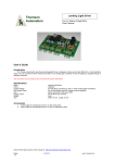
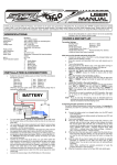
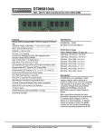
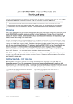
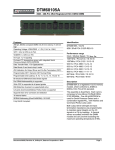
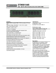
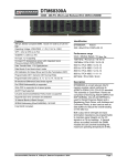
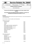
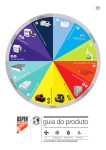
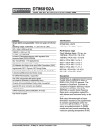
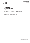
Landing Gear Controller II
Thomson
Automation
Input: Futaba, Output: Pin Headers
Adjustable Speed And Direction
7 Operating Modes inc. P-51
7 Servo Output Channels
Output For Landing Lights
Input For Wheels-up Switch
PC Interface
Table Of Contents
Introduction................................................................................................................................. 2
Connecting the module..............................................................................................................2
4-5Cell, NiCd / NiMh; 4.8V - 6.0V systems...............................................................................................2
Above 6.0V systems.................................................................................................................................2
Wheels-up Sensors...................................................................................................................................2
Landing Lights...........................................................................................................................................2
Multi functional pushbuttons.....................................................................................................................3
PC programming mode.............................................................................................................................3
Pushbutton programming mode................................................................................................................3
- Pushbutton..............................................................................................................................................3
+ Pushbutton.............................................................................................................................................3
S Pushbutton.............................................................................................................................................4
Programming (Settings).............................................................................................................4
Indicator LEDs............................................................................................................................4
Wheels-up Sensors....................................................................................................................4
Landing Lights............................................................................................................................ 5
Setting door and wheel positions (Settings 1 – 7)......................................................................5
Setting speeds of motions (Settings 8 & 9)................................................................................5
Finding cycle times ...................................................................................................................................5
Setting delays after door and wheel motions (Settings 10 & 11)................................................6
Setting the switching set point (Setting 12)................................................................................6
Selecting the operating mode (Setting 13).................................................................................6
Setting activation of the wheels-up switch (Setting 14)..............................................................7
Setting the starting position (Setting 15)....................................................................................7
Editing the program.................................................................................................................... 7
Operation.................................................................................................................................... 7
Start-up (Power-up)...................................................................................................................................8
1 Step Sequence ( Operating mode 5: All servos operate together)........................................................8
2 Step Sequence ( Operating mode 1: Normal landing gear cycle with 6 door servos and 1 wheels
servo)........................................................................................................................................................8
Check for the latest version of this manual at:
Page 1
11/13/2013
http://www.thomson-automation.com
user’s manual rev 2.0
2 Step Sequence ( Operating mode 2: Normal landing gear cycle with 4 door servos and 3 wheels
servos).......................................................................................................................................................8
3 Step Sequence (Operating mode 3: Double acting doors (P-51) with 6 door servos and 1 wheels
servo) .......................................................................................................................................................8
3 Step Sequence (Operating mode 4: Double acting doors (P-51) with 4 door servos and 3 wheels
servo) .......................................................................................................................................................9
7 Step Sequence (Operating mode 6: Servos operate one at a time with delays between 1-7, 7-1) .....9
7 Step Sequence (Operating mode 7: Servos operate one at a time with delays between 1-7, 1-7) ...10
Specifications ..........................................................................................................................10
Connections For Landing Lights...............................................................................................11
Connections For Wheels-up Switches.....................................................................................12
Connections For Servos...........................................................................................................13
User’s Guide
Introduction
The Thomson Automation 7-channel landing gear controller is a light weight automation controller
suitable for use in radio-controlled airplanes and other model vehicles using standard radio-control
servos. It can be used in either a 1, 2, 3 or 7-step sequence for controlling landing gear as well as other
types of sequential servo-controlled mechanisms. Operating modes 3 and 4 are used for double-acting
landing gear doors such as the in the P-51 where the doors close again after the wheels are lowered.
The input is a standard servo control signal and is used in normal operation to select gear-up or geardown. In case you forget to set your transmitter channel to “Gear Down” before you power-up the
module, it will not respond to commands until “Gear Down” is commanded for 2 seconds. After the
power-on safeties are satisfied, a change in the input channel initiates gear cycles The seven servo
output channels are sequentially driven at user-programmed speeds to the user-programmed positions.
All settings are stored in permanent memory. Channels 1-7 are used for programmed servo motions
and channel 8 is connected directly to the receiver input for use as a Y harness. Modules can be
coupled together for longer sequences or more control channels. Receiver channel expansion is
possible through using different switching threshold settings in parallel connected modules. A PC
interface and software are available for easier programming and more options. The PC serial interface
adapter must be purchased separately.
Connecting the module
4-5Cell, NiCd / NiMh; 4.8V - 6.0V systems
If everything is connected to one 4.8 to 6 volt power source simply plug the servos directly into the
module and the control cable into the receiver as in the connection diagram. A “y” harness can be used
to connect 2 or more servos to one output channel. To provide landing gear power from a secondary
battery, disconnect the + or middle wire in the receiver cable by cutting it or removing it from the
connector shell and use a “Y” harness on any of the servo output connectors to connect the secondary
battery. Always turn on the receiver before the LGC module or together with it.
Above 6.0V systems
For systems with more than 6 Volts, a reduced voltage must be supplied to the module.
Wheels-up Sensors
Switches for wheels-up sensing are connected to the “Wheels Up” connector. If the sensors are
used, they must be enabled by turning setting 14 on. Make sure that the “S” pushbutton is not pushed
while the unit is in operation. This pushbutton is connected in parallel with the “Wheels-Up connector.
Landing Lights
A signal for controlling landing lights is available at the R and F pins on the REMOTE connector.
See the connection diagrams for more information. The maximum current is 150ma. If LED’s are used
for landing lights, no external current limiting resistor is needed. Connect the 2 landing lights between
Check for the latest version of this manual at:
Page 2
11/13/2013
http://www.thomson-automation.com
user’s manual rev 2.0
the R-G and F-G pins on the Remote Control connector. (G is -, R and F are +) If you are using our
1098 Landing Lights, a splitter cable is available for a plug-and-play connection.
Multi functional pushbuttons
There are three programming pushbuttons on the module. These are labeled +, S and -. Each
pushbutton performs various functions depending on which setting is being changed. The F LED will
flash to indicate which setting is active and to give new settings values.
PC programming mode
A servo tester or receiver signal is not needed for PC programming. You can connect the LGCII
directly to a power source if desired. To enter the PC programming mode for use with the LGCII
manager software, hold the – pushbutton while powering up the module or click on “Connect” after the
module is powered-up. When starting the module in the PC mode, all doors will go immediately to the
open position and the wheels to the down position. If the LGCII is operating in a 3-step landing gear
mode, doors will close and wheels will go to the down position. Always lower the wheels before
powering down the module
Pushbutton programming mode
A servo tester or receiver is necessary for pushbutton programming. To enter the pushbutton
programming mode, hold the + pushbutton while powering up the module. When starting the module in
the pushbutton mode, there may be motion in the first servo channel depending on the input signal. As
other programming functions are selected, motion will occur in the corresponding servo channels.
- Pushbutton
The - pushbutton is used for the following functions:
1. For setting 1 (Door 1 position)
2. For setting 2 (Door 2 position)
3. For setting 3 (Door 3 position)
4. For setting 4 (Door 4 position)
5. For setting 5 (Door 5 position)
6. For setting 6 (Door 6 position)
7. For setting 7 (Wheels position)
8. For setting 8 (Door speed)
9. For setting 9 (Wheels speed)
10. For setting 10 (Wheels delay)
11. For setting 11 (Doors delay)
12. For setting 12 (Switching set point)
13. For setting 13 (Operating mode)
14. For setting 14 (Wheels Switch Activation)
15. For setting 15 (Starting Position)
pushing - sets the door 1 open position.
pushing - sets the door 2 open position.
pushing - sets the door 3 open position.
pushing - sets the door 4 open position.
pushing - sets the door 5 open position.
pushing - sets the door 6 open position.
pushing - sets the wheels down position.
pushing - decreases the door speed.
pushing - decreases the wheels speed.
pushing - decreases the after-doors delay 0.1 sec.
pushing - decreases the after-wheels delay 0.1 sec.
pushing - stores the new set point
pushing - decreases the operating mode number by 1
pushing - deactivates the wheels switch (LED off)
pushing - sets wheels-up as the starting position
During power-up, holding the – pushbutton causes the module to enter the PC programming mode.
+ Pushbutton
The + pushbutton is used for the following functions:
1. For setting 1 (Door 1 position)
2. For setting 2 (Door 2 position)
3. For setting 3 (Door 3 position)
4. For setting 4 (Door 4 position)
5. For setting 5 (Door 5 position)
6. For setting 6 (Door 6 position)
7. For setting 7 (Wheels position)
8. For setting 8 (Door speed)
9. For setting 9 (Wheels speed)
10. For setting 10 (Wheels delay)
11. For setting 11 (Doors delay)
12. For setting 12 (Switching set point)
13. For setting 13 (Operating mode)
Check for the latest version of this manual at:
Page 3
11/13/2013
pushing + sets the door 1 closed position.
pushing + sets the door 2 closed position.
pushing + sets the door 3 closed position.
pushing + sets the door 4 closed position.
pushing + sets the door 5 closed position.
pushing + sets the door 6 closed position.
pushing + sets the wheels up position.
pushing + increases the door 1 speed.
pushing + increases the wheels speed.
pushing + increases the after-doors delay 0.1 sec.
pushing + increases the after-wheels delay 0.1 sec.
pushing + stores the new set point
pushing + increases the operating mode number by 1
http://www.thomson-automation.com
user’s manual rev 2.0
14. For setting 14 (Wheels Switch Activation)
15. For setting 15 (Starting position)
pushing + activates the wheels switch (LED on)
pushing + sets wheels-down as the starting position
During power-up, holding the + pushbutton causes the module to enter the pushbutton programming
mode.
New position settings, new switching setpoint and wheels-up switch activation setting are stored
immediately in permanent memory. For other settings (speeds, delays and operating mode select)
always press S after making changes. These settings are stored in permanent memory only after S is
pressed.
S Pushbutton
The S pushbutton is used for selecting the setting during programming. It is also used in
combination with the other pushbuttons for setting default, minimum and maximum values.
Make sure that the pushbuttons are not pushed while the unit is in operation and that wheels-up
switches are not connected during pushbutton programming. Wheels-up switches can be used during
LGC Manager programming.
Programming (Settings)
For instructions on using a PC with LGCII Manager software, see the LGCII Manager help files.
To enter the LGCII Manager programming mode:
1. Push and hold the – pushbutton while powering-up the module.
To enter the pushbutton programming mode:
1. Push and hold the + pushbutton while powering-up the module.
2. The F LED will flash once to indicate setting 1 after the pushbutton is released.
3. There will be a 1 second delay before the start of the flashes.
To select the next setting:
1. Push the S pushbutton.
2. The number of flashes by the F LED will indicate which setting is active
3. There will be a 1 second delay before the start of the flashes.
To select other settings:
1. Push and hold the S pushbutton.
2. Push + or – to one or more times to select higher or lower settings.
3. Release the S pushbutton.
4. The number of flashes by the F LED will indicate which setting is active
5. There will be a 1 second delay before the start of the flashes.
Caution: settings 1-7 will cause servo motion
When finished, re-boot the module by one of two methods.
1. turning the power off and then back on.
2. Press “S” again at the last setting (15).
Indicator LEDs
In programming Mode:The 'F' LED flashes In settings modes to indicate the selected mode and the
selected settings values. The 'R' LED is not used during programming.
In operating mode: Both LEDs indicate the state of the landing light outputs.
During normal power-up, the LEDs and the landing lights will only turn on after the 5 second poweron delay and “Gear Down” in commanded for 2 seconds.
Wheels-up Sensors
To overcome problems with variable speeds of air-powered retracts caused by on decaying air
pressure and variable wind loading, a wheels-up sensor input is available. Connecting this input to
Check for the latest version of this manual at:
Page 4
11/13/2013
http://www.thomson-automation.com
user’s manual rev 2.0
switches on the retracts causes the sequence to wait to close the doors until the wheels are completely
retracted instead of closing after a user-programmed time delay. Typically, reed switched are connected
to the pins on the 'WHEELS Up' connector. (See connection diagrams) Optional reed switches, a
connection harness and actuating magnets are available. If the sensors are not used, either attach a
shorting jumper to the sensor input or turn off setting 14. The module is shipped from the factory with
the sensors deactivated. Setting 14 must be changed to activate the switch input.
Be sure to disconnect the sensors during pushbutton programming. They use the same input as
one of the programming pushbuttons.
Landing Lights
Two outputs are available for landing lights. They will turn on at the beginning of the gear-down
cycle and turn off at the end of the gear-up cycle. They can be connected at the 'REMOTE' connector.
See the connection diagram.
Setting door and wheel positions (Settings 1 – 7)
For these pushbutton mode settings, the receiver connection must be connected to a receiver with
an active transmitter joystick or slider channel or a servo test box. During position settings modes the
receiver channel will be fed directly the chosen output channel.
To set the end points of the door and wheels servo motions:
1. Select the channel you want to program, (See page 3)
2. Set the door or wheels at the desired position through the receiver channel.
3. Push + to store the Wheels-up or doors-closed position, push – to store the Wheels-down or
doors-open position
4. The LED flashes to indicate permanent storage of the setting.
5. Repeat 2 - 4 for both ends of travel.
Every time that + or - is pushed, a new position will be recorded. The new settings are immediately
stored in permanent memory.
Setting speeds of motions (Settings 8 & 9)
Setting different speeds of individual door channels is only possible through the PC link using the LGCII
Manager software . Using the pushbuttons sets all door speeds to the same value.
To change the speed of the servo motion:
1. Select setting 8 or 9 for doors or wheels speed.
2. Push – to decrease the speed or + to increase the speed.
3. Count the flashes and use the formula below to determine the traverse time.
4. Pushing + and – together sets the speed to (25).
5. Pushing + and S together sets the speed to (50).
6. Pushing – and S together sets the speed to (10).
When using two pushbuttons together to set min, max or mid range, always push + or – first to avoid
selecting the next setting. Door and wheels speed settings will be applied to all door and wheels servos.
For separate setting of speeds for each servo channel, use the LGCII Manager software and the
needed communication adapters.
After the setting is changed, push “S” to store the new setting in permanent memory otherwise, it will
not be retained.
The “F” LED will flash to indicate that the values have been stored. The “F” LED will flash 3 times for
each door channel storage and 3 times for wheels speed storage.
Finding cycle times
(4 * number of sequence steps [2 or 3] / LED flashes)
Check for the latest version of this manual at:
Page 5
11/13/2013
http://www.thomson-automation.com
user’s manual rev 2.0
Settings 8 and 9 result in a motion speed setting for the corresponding servos. Traverse times will
therefore vary depending on the speed setting as well as the total travel and also on the speed of the
servo. To calculate the approximate travel time divide 4 seconds per servo motion by the number of
flashes of the LED. For a 3-step gear sequence at the minimum speed this will result in around 12
seconds total cycle time. For operation of air valves by the servos the speed is normally set to a high
value. (>200)
Setting delays after door and wheel motions (Settings 10 & 11)
For systems that use servo-operated air valves, a delay is required after the servo motion is
complete to allow time for the air cylinders to move.
To change the delay setting:
1. Select setting 10 or 11 for door or wheels delay.
2. Push – to decrease the delay or + to increase the delay.
3. Count the flashes. Each flash = 0.1 sec delay.
4. Pushing + and – together sets the delay to 1.5 seconds.
5. Pushing + and S together sets the delay to 3 seconds.
6. Pushing – and S together sets the delay to 0.1second.
It is possible to set the delays to a maximum value of 5 seconds by pressing the + pushbutton. Door
and wheels delay settings will be applied to all door and wheels servos. For separate setting of delays
for each servo channel, use the LGCII Manager software and the needed communication adapters.
After the setting is changed, push “S” to store the new setting in permanent memory otherwise, it will
not be retained.
The “F” LED will flash to indicate that the values have been stored.
Setting the switching set point (Setting 12)
For these pushbutton mode settings, the receiver connection must be connected to a receiver with an
active transmitter joystick or slider channel or a servo test box. The point on the input signal where the
module is adjustable. By using two or more modules in parallel multiple sequences can be controlled
from one receiver channel. The default switching point is in the middle of the range.
To change the switching set point:
1. Select setting 12 for switching set point.
2. Set the receiver channel to the desired set point
3. Push either the + or - pushbutton.
The new setting is immediately stored in permanent memory.
Selecting the operating mode (Setting 13)
To change the operating mode:
1. Select setting 13.
2. Push CLOSED to select a higher mode number: or
3. Push OPEN to select a lower mode number
The LED will flash to indicate the selected mode number. The following operating modes are available:
1. Two-step sequence; For Normal landing gear use with wheels and doors. 6 doors, 1 wheels.
2. Two-step sequence; For Normal landing gear use with wheels and doors. 4 doors, 3 wheels.
3. Three-step sequence for P-51 type landing gear. Doors close after each wheel motion. 6 doors,
1 wheels.
4. Three-step sequence for P-51 type landing gear. Doors close after each wheel motion. 4 doors,
3 wheels.
5. One-step sequence; All 7 servos operate together.
6. Seven-step sequence for general automation purposes. Servo 1 – Servo 7, Servo 7 – Servo 1
7. Seven-step sequence for general automation purposes. Servo 1 – Servo 7, Servo 1 – Servo 7
The new setting are not immediately stored in permanent memory. To store the new setting, push
the “S” pushbutton to select the next setting (14). This also stores the mode setting. See the Operation
Check for the latest version of this manual at:
Page 6
11/13/2013
http://www.thomson-automation.com
user’s manual rev 2.0
section below for a more detailed description of the operating modes. Reversing you transmitter
channel may be necessary to control the cycle properly. There is a difference between the gear-up and
gear-down cycles. To find out if you need to reverse your channel, check the LEDs on the module. They
are parallel indicators for the landing lights and will turn on at the beginning of the gear-down cycle and
turn off at the end of the gear-up cycle.
Setting activation of the wheels-up switch (Setting 14)
If activated, the closing of the doors will wait for both the wheels delay and the wheels-up switch
To activate the switch: (The switch will be used)
1. Select setting 14.
2. Push +.
3. The LED will turn on.
To deactivate the switch: (The switch will not be used)
1. Select setting 14.
2. Push -.
3. The LED will turn off.
The new settings are immediately stored in permanent memory.
Setting the starting position (Setting 15)
This setting determines the initial position that is assumed at power-up. The landing gear is
expected to be in this position when the power is turned on. All servos will go immediately at maximum
speed to this position. Normally, they will already be there so no motion will occur. Always set the
wheels in this position before powering down the module
To activate the switch: (The switch will be used)
4. Select setting 15.
5. Push +.
6. The LED will turn on.
To deactivate the switch: (The switch will not be used)
4. Select setting 15.
5. Push -.
6. The LED will turn off.
The new settings are immediately stored in permanent memory.
Editing the program
Selecting a setting does not change the old setting until a new value is entered. If no changes are
made in a setting before the next setting is selected, the old setting value will be retained. To skip a
setting, select the next setting without making any changes. Set the new value as in the description.
The module can be restarted at any time by turning the power off and then back on. To quickly select a
setting number, hold the S pushbutton and press either + or – the correct number of times to take you
to a different setting.
Some new settings values are not stored immediately on their entry. For these settings, it is necessary
to select the next setting by pushing the S pushbutton. Permanent data storage in EEPROM is
indicated by 3 flashes of the F LED for each value stored.
Operation
Settings mode 13 sets the operating mode of the device. The incoming signal is used as an on-off
function and will switch at the programmed threshold. Crossing the threshold causes the full sequence
to run. (Up or down depending on the direction of the input change.)
Check for the latest version of this manual at:
Page 7
11/13/2013
http://www.thomson-automation.com
user’s manual rev 2.0
Start-up (Power-up)
All servos immediately go to the gear-down position. In the 3-step modes, this means that doors are
closed and wheels are down. In all other modes, Doors are open and wheels down. Always lower your
landing gear before powering-down the module. During power-up, turn on and the module will only
respond to an input servo signal after the 5 second power-on delay. The LEDs and the landing lights
will only turn on after “Gear Down” in commanded for 2 seconds. After this 2 second “Gear Down”
command, the module will respond to all servo input commands.
.
1 Step Sequence ( Operating mode 5: All servos operate together)
1-Step Gear-down sequence (Operating mode 5)
1. A gear-down command is received from the receiver channel
2. All servos run to the programmed gear-down position
1-Step Gear-up sequence (Operating mode 5)
1. A gear-up command is received from the receiver channel
2. All servos run to the programmed gear-up position
2 Step Sequence ( Operating mode 1: Normal landing gear cycle with 6 door servos and 1
wheels servo)
2-Step Gear-down sequence (Operating mode 1)
1. A gear down command is received from the receiver channel
3. The doors open (Channels 1 - 6)
4. Time delay
5. The wheels are lowered (Channel 7)
2-Step Gear-up sequence (Operating mode 1)
1. A gear up command is received from the receiver channel
2. The wheels are raised (Channel 7)
3. Time delay (And wheels-up switch if activated)
4. The doors close (Channels 1 – 6)
2 Step Sequence ( Operating mode 2: Normal landing gear cycle with 4 door servos and 3
wheels servos)
2-Step Gear-down sequence (Operating mode 2)
1. A gear down command is received from the receiver channel
6. The doors open (Channels 1 - 4)
7. Time delay
8. The wheels are lowered (Channel 5-7)
2-Step Gear-up sequence (Operating mode 2)
5. A gear up command is received from the receiver channel
6. The wheels are raised (Channel 5-7)
7. Time delay (And wheels-up switch if activated)
8. The doors close (Channels 1-4)
3 Step Sequence (Operating mode 3: Double acting doors (P-51) with 6 door servos and 1
wheels servo)
P-51 Gear-down sequence (Operating mode 3)
1. A gear down command is received from the receiver channel
2. The doors open (Channels 1-6)
3. Time delay
4. The wheels are lowered (Channels 7)
5. Time delay
Check for the latest version of this manual at:
Page 8
11/13/2013
http://www.thomson-automation.com
user’s manual rev 2.0
6. The doors close (Channels 1-6)
P-51 Gear-up sequence (Operating mode 3)
1. A gear up command is received from the receiver channel
2. The doors open (Channels 1-6)
3. Time delay
4. The wheels are raised (Channel 7)
5. Time delay (And wheels-up switch if activated)
6. The doors close (Channels 1-6)
3 Step Sequence (Operating mode 4: Double acting doors (P-51) with 4 door servos and 3
wheels servo)
P-51 Gear-down sequence (Operating mode 4)
1. A gear down command is received from the receiver channel
2. The doors open (Channels 1-4)
3. Time delay
4. The wheels are lowered (Channels 5-7)
5. Time delay
6. The doors close (Channels 1-4)
P-51 Gear-up sequence (Operating mode 4)
1. A gear up command is received from the receiver channel
2. The doors open (Channels 1-4)
3. Time delay
4. The wheels are raised (Channel 5-7)
5. Time delay (And wheels-up switch if activated)
6. The doors close (Channels 1-4)
7 Step Sequence (Operating mode 6: Servos operate one at a time with delays between 1-7, 7-1)
Sequential Gear-down operation (Operating mode 6)
1. A gear down command is received from the receiver channel
2. Channel 1 runs to the programmed down position
3. Time delay
4. Channel 2 runs to the programmed down position
5. Time delay
6. Channel 3 runs to the programmed down position
7. Time delay
8. Channel 4 runs to the programmed down position
9. Time delay
10. Channel 5 runs to the programmed down position
11. Time delay
12. Channel 6 runs to the programmed down position
13. Time delay
14. Channel 7 runs to the programmed down position
Sequential Gear-up operation (Operating mode 6)
1. A gear up command is received from the receiver channel
2. Channel 7 runs to the programmed up position
3. Time delay
4. Channel 6 runs to the programmed up position
5. Time delay
6. Channel 5 runs to the programmed up position
7. Time delay
8. Channel 4 runs to the programmed up position
9. Time delay
10. Channel 3 runs to the programmed up position
11. Time delay
12. Channel 2 runs to the programmed up position
Check for the latest version of this manual at:
Page 9
11/13/2013
http://www.thomson-automation.com
user’s manual rev 2.0
13. Time delay
14. Channel 1 runs to the programmed up position
7 Step Sequence (Operating mode 7: Servos operate one at a time with delays between 1-7, 1-7)
Sequential Gear-down operation (Operating mode 7)
1. A gear down command is received from the receiver channel
2. Channel 1 runs to the programmed down position
3. Time delay
4. Channel 2 runs to the programmed down position
5. Time delay
6. Channel 3 runs to the programmed down position
7. Time delay
8. Channel 4 runs to the programmed down position
9. Time delay
10. Channel 5 runs to the programmed down position
11. Time delay
12. Channel 6 runs to the programmed down position
13. Time delay
14. Channel 7 runs to the programmed down position
Sequential Gear-up operation (Operating mode 6)
1. A gear up command is received from the receiver channel
2. Channel 1 runs to the programmed up position
3. Time delay
4. Channel 2 runs to the programmed up position
5. Time delay
6. Channel 3 runs to the programmed up position
7. Time delay
8. Channel 4 runs to the programmed up position
9. Time delay
10. Channel 5 runs to the programmed up position
11. Time delay
12. Channel 6 runs to the programmed up position
13. Time delay
14. Channel 7 runs to the programmed up position
For systems that do not require delays, the delay value can be set to 0.0 sec.
In all operating modes everything goes to the programmed starting position on power-up. If it is
already there, nothing will move so always set the gear to the starting position before powering down.
Specifications
Name
Part nr.
Hardware rev
Firmware rev
Supply Voltage
Supply current
Servo Channels
Control Channels
Landing Gear Controller 2
1070L
2.0
2.7.0
3.5V – 6.5V
5 ma
1 in, 8 out (1 Is An Input Follower)
1 Input For Wheels-up Sensors
2 Outputs For Landing Lights
(Sourcing) 150 ma for Landing Lights
3.5V – 6.5V
1.25V – 5V pulse
15 gm
27 mm X 62 mm
29 cm
Maximum Output Current
Control Input Voltage
Receiver Control Signal
Weight
Board Size
Cable Length
Check for the latest version of this manual at:
Page 10
11/13/2013
http://www.thomson-automation.com
user’s manual rev 2.0
Slowest Traverse Time:
Fastest Traverse Time:
20 Sec*
Per receiver input
* Times will vary depending on the programmed speed and distance of motion and the native speed of the
servo.
The landing gear controller is intended for hobby use only. Thomson Automation is not responsible for
any damage or injury that occurs through the use of this product.
Connections For Landing Lights
LEDs can be connected directly for use as landing lights. 150Ma Max.
See http://www.thomson-automaiton.com for information on our landing light products.
Connections For Wheels-up Switches
Check for the latest version of this manual at:
Page 11
11/13/2013
http://www.thomson-automation.com
user’s manual rev 2.0
Connections For Servos
Check for the latest version of this manual at:
Page 12
11/13/2013
http://www.thomson-automation.com
user’s manual rev 2.0