1
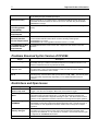
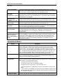
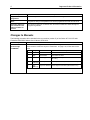
December 21, 2004 GFK-2345A Important Product Information READ THIS INFORMATION FIRST Product: IC693CPU366 CPU Module with PROFIBUS Master IC693CPU366-AB with CPU Firmware Version 10.72 PROFIBUS Firmware Version 1.01 This document contains information that is not available in any other publication; therefore we recommend you save it for future reference. This is release of the IC693CPU366 CPU with Embedded PROFIBUS Master resolves the issues listed below. This is an update for the firmware on the PROFIBUS daughter board. Documentation Instructions for using the IC693CPU366 module can be found in the latest version of the following manuals: Series 90™-30 CPU with Embedded PROFIBUS Master User’s Manual, GFK-2334 Series 90-30 Installation and Hardware Manual, GFK-0356 Series 90-30/20/Micro CPU Instruction Set Reference Manual, GFK-0467 Updates To upgrade a CPU366 to the latest version (-AB), you must purchase the field upgrade kit 44A751640-G02 or download it at no charge from the web (http://globalcare.gefanuc.com/). Firmware upgrades require the IC690ACC901 Miniconverter and Cable Kit. Functional Compatibility Subject Description Get Device Status COMMREQ The Get Device Status COMMREQ is used to get detailed status information about a particular device on the PROFIBUS network. In order to get the most up to date data, a change was made after the initial release to make this an active network command. In the first release, this information was returned to the user application based on buffered data. After the initial release, this data is actively requested from the network. If the user application uses the Get Device Status COMMREQ often, there is a potential to impact network performance. Series 90 -30 PROFIBUS Compatibility Customers using existing Series 90-30 PROFIBUS products should review the CPU366 User’s Manual, GFK-2334. Changes have been made in items such as CommReq status words and data fields. This module reports additional information in some instances and less information in other instances. This product also supports PROFIBUS DP-V1 functionality. Programmer Version Requirements The IC693CPU366 can be configured and programmed with Machine Edition Logic Developer PLC version 5.0 SP1 or later. Total Configuration Size The various memory resources within the PLC CPU constrain the number and type of slave devices and the amount of data they can exchange with the master. The amount of memory available for the PROFIBUS configuration is affected by the number and type of slave modules in the network configuration. The CPU366 provides up to 16k bytes of resource data. This is defined by each slave module’s GSD file, and can vary depending on the types of modules. 2 Important Product Information GFK-2345A Data Sizes The amount of data that can be configured on the CPU 366 PROFIBUS network provides up to 2048 bytes input and 2048 bytes output. DOIO Functionality DOIO functionality is not supported to the embedded PROFIBUS interface at this time. The DOIO function block does not return an error if it is executed using the embedded PROFIBUS as a target. Series 90-30 HandHeld Programmer Compatibility The CPU366 does not support PROFIBUS configuration using the Hand-Held Programmer (HHP). PLC C Toolkit Version Requirements Version 4.00 or later of the PLC C Toolkit must be used for C programming. IC693CMM321 Ethernet Interface Version Requirements All Ethernet Interface (IC693CMM321) modules used for programmer or HMI/SCADA communications with this CPU must be one of the following revision groups: IC693BEM340 FIP Bus Controller Version Requirements IC693BEM340 firmware version 3.00 or later is required for this release of CPU 36x firmware. IC693CMM321-CC or later IC693CMM321-AA or -BA upgraded to firmware version 1.11 or later Problems Resolved by this Version of CPU366 Subject Description Sync/Freeze trigger A change was made to make the sync/freeze trigger bit behave like the IC693PBM200. Previously, the sync or freeze command was only sent on a transition from zero to one. Now the command is sent on any transition of the bit. DP-V1 Write data response area In the first release, the response data area for a DP-V1 write request contained a copy of the data written. This is an extra duplication of data, and was removed so that the operation now matches the user’s manual. CPU lockup when using DP-V1 This release fixes a problem that occurred when processing many DP-V1 requests while handling heavy communications traffic (serial, Ethernet, PCM, CMM). The user may have seen the run/stop keyswitch stop responding, or non-operational timers and timer contacts. Restrictions and Open Issues Subject Description No PROFIBUS Loss/Add faults in stop mode When the CPU is in Stop mode, no “Loss of module” or “Addition of module” faults are logged. Once the unit is changed to RUN mode, these faults are logged Slave Diagnostic Status Word The Slave Diagnostic Status Word is currently reporting the address of a slave on the network that has a physical network error. This data was intended to represent the address of a slave that has a diagnostic message to report. This will be fixed in a future release, so user applications should be coded so that a change will not impact operation. Get Device Diagnostics COMMREQ The CPU366 Get Device Diagnostics returns only the extended diagnostic data. Previous PROFIBUS products also reported the standard diagnostics data. This will be fixed in a future release, so user applications should be coded so that a change will not impact operation. COMMREQ response memory data types Do not use %I, %Q, %M or %T for the PROFIBUS CommReq response data. The CPU366 is not using the offset correctly when returning data using the BYTE offset segments associated with %I, %Q, %M and %T memories. Use of these reference types is supported for COMMREQ status words. Format of Loss/Add When either a Loss Of Device or Addition Of Device fault is reported in the IO Fault table, Important Product Information 3 GFK-2345A Faults in the IO table the location is always listed as 0#0.0. The slave address is listed in byte 5 of the fault extra data. The ref address indicated in the IO Fault table will always show the reference associated with the lowest configured slave in the PROFIBUS network. No fault in fault table if PROFIBUS configuration is rejected If the PROFIBUS configuration is rejected by the CPU 366 after a download has completed, there is no fault in the fault table. The slave status bits will not be set, and the LED pattern will be SYS off, and COM blinking green. This indicates that the PROFIBUS daughterboard is not configured. Validation of Reference Table Sizes with COMMREQ return data If a COMMREQ is used to read PROFIBUS information, the user must verify that the memory reference type they are using is correct. If an invalid identifier is used, no data will be returned to the reference table, yet the status word may indicate a value of OK (1). Extra “Addition of Device” faults An “Addition of Device” fault is put in the fault table for each device in the PROFIBUS network configuration either after a download or on the transition to run. LED Operation with failed CPU If a CPU Motherboard is lost and the PROFIBUS daughterboard is still operational, it will put the network into Clear Mode, but the LED will not indicate this. The OK LED will be out on the power supply indicating the CPU is non-operational. LED Operation with Short Circuit Bus Shorting certain wires in the PROFIBUS network may cause the unit to drop off of the bus. The slave diagnostic bits will indicate a zero. Depending on the type of the short, the SYS and COM LEDs may both on for some period. More data can be obtained in the diagnostic data. Profibus DPV1 Communications: Slave Failure to Respond Causes Repeated Error Status If the CPU366 times out waiting for a response from a slave to a DPV1 Read or Write request COMMREQ, it reports a DPV1 Request Status of 129 decimal - "Master is about to stop DPV1 communication or DPV1 is not in Open state." After receiving this error, subsequent DPV1 COMMREQs may continue to report DPV1 Request Status 129. To clear this state, download a new hardware configuration to the CPU366 or turn the CPU366 off and back on. Operational Notes Subject Description User Flash Contents The user program, configuration, CPU ID (used for SNP communication), and reference memory tables stored in RAM will automatically be cleared when the CPU firmware in flash memory is changed. You will need to restore these when upgrading from a previous firmware version. The user program, configuration, and reference memory (%R, %AI, %AQ, %I, %Q, %T and %M) tables can be restored from a PLC programmer folder or from flash. The SNP ID must be set separately, using the PLC programmer or the HHP. The faults, overrides and transition tables cannot be stored to flash. The overrides may be restored from the programmer or folder, but the faults and transitions are lost. Writing Flash Memory When writing very large programs to flash, you may need to increase the request timeout value in the programming software to avoid receiving a request timeout message. An upper bound of 25 seconds is typically satisfactory. Storing Large Configurations A Series 90-30 PLC using a CPU 36x supports a maximum of 32 DSM314 modules. This number is reduced when other intelligent modules are used in the PLC, such as APM and GBC modules. It may also be reduced when: The number of racks in the PLC increases; The total size of logic, motion and AUP files increases; The application uses C logic blocks or a C logic program; and Connected programmers or HMI devices are used to read reference memory or fault tables. In some cases it may be possible to increase the number of DSM314 modules that the CPU 36x will accept in the hardware configuration by storing logic first and then storing the configuration separately. No Model Number Checking with LM90 The Logicmaster 90-30 “No Model Number Checking” feature does not support storing a CPU 311, 313, 321, 323 or 331 configuration to a Release 9.00 or later Series 90-30 CPU. 4 Important Product Information GFK-2345A Subject Logicmaster 90-30 programmer Description Do not attempt to store CPU 311, 313, 321, 323 or 331 configurations to a CPU36x. Simultaneous Load and Store When operating with multiple programmers attached, initiating a store operation from one programmer during a load operation from another programmer will cause the load to fail. Transition Tables are not cleared when the reference tables are cleared. The transition tables are not cleared when the reference tables are cleared through the programming software. Changes to Manuals The following correction will be included in the next revision (version C) of the Series 90™-30 CPU with Embedded PROFIBUS Master User’s Manual, GFK-2334. Subject DP-V1 Alarm Acknowledge COMMREQ Description In order to acknowledge alarms with sequence numbers greater than 0, the DP-V1 status word needed to include the sequence number data. On page 5-24, the first table should read: Word Byte Name Description 1 Low Slave Address Address of slave with alarm 1 High Slot Number Slot number of alarm 2 Low Alarm Type Type of the alarm. (Valid values are 1—6 and 32—126.) 2 High Alarm Spec ( Bits 0-2 ) 2 High (Bits 3-7) Alarm Specification. (Valid values are 0—7.) Sequence Number Alarm Sequence Number (Valid values 0-31.)