1
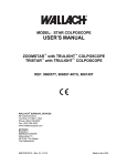
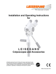
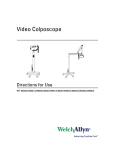
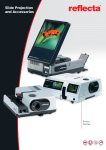
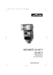
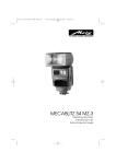
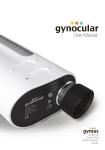
Optical Colposcope with
Tilt Stand
REF 88200
Optical Colposcope with Swing
Arm Roller Stand
REF 88460
Operating Instruction Manual
Table of Contents
Warnings and Cautions . . . . . . . . . . . . . . . . . . . . . . . . . . . . . . . . . . . . . . . . . . . . . . . . . . . . . .1
General Precautions . . . . . . . . . . . . . . . . . . . . . . . . . . . . . . . . . . . . . . . . . . . . . . . . . . . . . . . . .1
Tilt Stand Assembly . . . . . . . . . . . . . . . . . . . . . . . . . . . . . . . . . . . . . . . . . . . . . . . . . . . . . . . . .2
Swing Arm Universal Mount Assembly . . . . . . . . . . . . . . . . . . . . . . . . . . . . . . . . . . . . . . . . .3
Height Adjustment of the Swing Arm . . . . . . . . . . . . . . . . . . . . . . . . . . . . . . . . . . . . . . . . . . . . . . . . . . 3
Roller Stand Assembly . . . . . . . . . . . . . . . . . . . . . . . . . . . . . . . . . . . . . . . . . . . . . . . . . . . . . . .4
Colposcope Assembly And Operation . . . . . . . . . . . . . . . . . . . . . . . . . . . . . . . . . . . . . . . . . .4
Optical Adjustments . . . . . . . . . . . . . . . . . . . . . . . . . . . . . . . . . . . . . . . . . . . . . . . . . . . . . . . . . . . . . . . . . 5
Adjustment of Ocular Eye Pieces . . . . . . . . . . . . . . . . . . . . . . . . . . . . . . . . . . . . . . . . . . . . . . . . . . . . . . 5
Special Eyepieces . . . . . . . . . . . . . . . . . . . . . . . . . . . . . . . . . . . . . . . . . . . . . . . . . . . . . . . . . . .5
Green Filters . . . . . . . . . . . . . . . . . . . . . . . . . . . . . . . . . . . . . . . . . . . . . . . . . . . . . . . . . . . . . . .5
Adjustment Of Tilt . . . . . . . . . . . . . . . . . . . . . . . . . . . . . . . . . . . . . . . . . . . . . . . . . . . . . . . . . .6
Reversing The Fine Focus Handle . . . . . . . . . . . . . . . . . . . . . . . . . . . . . . . . . . . . . . . . . . . . . .6
Resetting The Height Adjustment Handle . . . . . . . . . . . . . . . . . . . . . . . . . . . . . . . . . . . . . . .7
Changing Position Of Transformer . . . . . . . . . . . . . . . . . . . . . . . . . . . . . . . . . . . . . . . . . . . . .8
Colposcope Care And Maintenance . . . . . . . . . . . . . . . . . . . . . . . . . . . . . . . . . . . . . . . . . . . .8
Lamp Replacement . . . . . . . . . . . . . . . . . . . . . . . . . . . . . . . . . . . . . . . . . . . . . . . . . . . . . . . . . .8
Checking the Lighting System . . . . . . . . . . . . . . . . . . . . . . . . . . . . . . . . . . . . . . . . . . . . . . . . . . . . . . . . . 9
Video Adapter . . . . . . . . . . . . . . . . . . . . . . . . . . . . . . . . . . . . . . . . . . . . . . . . . . . . . . . . . . . . . .9
Mounting the Video Adapter . . . . . . . . . . . . . . . . . . . . . . . . . . . . . . . . . . . . . . . . . . . . . . . . . . . . . . . . . . 9
Attaching the Video Camera . . . . . . . . . . . . . . . . . . . . . . . . . . . . . . . . . . . . . . . . . . . . . . . . . . . . . . . . . 10
Adjusting the Video Device . . . . . . . . . . . . . . . . . . . . . . . . . . . . . . . . . . . . . . . . . . . . . . . . . . . . . . . . . . 10
Focusing and Adjusting the Multi-Mag Video Adapter . . . . . . . . . . . . . . . . . . . . . . . . . . . . . . . . . . . . 11
Checking the Link Setting of the Video Camera . . . . . . . . . . . . . . . . . . . . . . . . . . . . . . . . . . . . . . . . . 11
Replacement Parts . . . . . . . . . . . . . . . . . . . . . . . . . . . . . . . . . . . . . . . . . . . . . . . . . . . . . . . . .12
Warranty . . . . . . . . . . . . . . . . . . . . . . . . . . . . . . . . . . . . . . . . . . . . . . . . . . . . . . . . . . . . . . . . .12
One Year Limited Warranty On New Instruments . . . . . . . . . . . . . . . . . . . . . . . . . . . . . . . . . . . . . . . . 12
Service . . . . . . . . . . . . . . . . . . . . . . . . . . . . . . . . . . . . . . . . . . . . . . . . . . . . . . . . . . . . . . . . . . .12
Warnings and Cautions
WARNING: DO NOT use a converter
adapter that will convert the three-prong
AC plug to a two-prong line plug. The
power supply in the colposcope will not
be properly grounded and electric shock
might result.
WARNING: The lamp operates at a high
temperature. DO NOT attempt to remove
the lamp before allowing it to cool. Allow
at least five minutes for the lamp to cool
before replacing.Replace with Welch Allyn
lamp #08100 only.
CAUTION: Federal law restricts this
device to sale by on the or order of a physician or other appropriately licensed medical professional.
General Precautions
•
For safety, the colposcope should only be coupled to
a grounded 110-120 VAC hospital-grade outlet.
•
The colposcope should not be operated in the presence of flammable or explosive gases or chemicals,
or installed in areas where these materials are commonly used.
•
To avoid overheating, the colposcope should not be
positioned closer than 6” to any wall.
•
Keep all liquids away from electrical equipment to
avoid the possibility of shock and instrument damage.
•
Occasionally inspect the power cord for signs of
cuts, abrasions or dents.
•
The colposcope should never be stored or operated
in areas where it could get wet or could be exposed
to any environmental conditions like extreme temperature or humidity, direct sunlight, dust, etc.
•
The lamp is extremely bright. DO NOT stare directly
into illumination lens when the lamp is lit.
•
All service to the video colposcope must be performed by Welch Allyn or by an authorized repair center.
•
Colposcope user should adhere to the operating conditions found in this manual. Otherwise, instrument
damage may occur and/or operator/patient safety
may be compromised.
•
There are no user serviceable parts (other than the
lamp and fuses) in this unit or in its accessories. Any
attempt to disassemble and/or repair this unit will
result in voiding of the warranty.
•
Colposcope device to patient distance no closer than
19 cm. Closer distances have higher irradiance levels
and may cause thermal skin injury. Short intermittent
exposures in and out of the illumination path by the
user at closer distances is typical of cervical examinations. Prolonged exposures are not recommended.
CAUTION: The device is for OB/GYN purposes only.
Symbols
Caution: Consult user's manual for
additional information.
Warning: High temperatures
Risk of fire. Replace fuses as
marked.
Warning: High-intensity light
Warning: Power supply of unit is
energized whenever power cord is
plugged in.
Dangerous Voltage
UL Recognized Component
UL Listed
1
Tilt Stand Assembly
Lay the Tilt Stand so that as the colposcope head is tilted
forward and remains stationary without continuing in a
forward motion.
The narrow side of the base plate and transformer must
face the operator when in use. The operator should place
his/her feet onto the base plate when using the colposcope.
Align the ball joint to base plate with the four bolts and
washers.
Use the socket wrench provided to tighten the four outer
bolts securely.
The adjustment knob (A) is used for the gross height
adjustment of the colposcope.
Use the red bolt centered on the bottom of the base
plate for adjusting the tilt friction of the ball joint. Tighten
the red bolt to the desired tilt friction so that the colposcope head remains stationary or tilts with moderate
pressure. (Clockwise increases tilt friction, counter-clockwise decreases tilt friction).
A
NOTE:
Do not overtighten the red bolt.
NOTE:
The tilting friction of the ball joint may loosen
with use. Retighten as necessary.
2
Swing Arm Universal
Mount Assembly
A rigid connection is required when mounting the swing
stand to an examination table/chair. For maximum steadiness, mount the clamps as high up and as low down as
possible on the vertical support column.
Height Adjustment of the Swing Arm
Lift the Swing Arm up and pull the pin (A) from the height
fixing ring. Place the ring to the desired height until it
engages the holes (B) of the tubular support. Then carefully set the Swing Arm down in place.
A
One ball-clamp consists of two halves on which one side
is lined with sand paper. This side surrounds the leg of
the examination chair or clamps onto the table mount
provided. The other side of the ball clamp attaches to the
black ball.
NOTE:
B
If the swing stand is mounted to the left side of the
examination table/chair, reverse the light transformer.
(See “Changing Position Of Transformer” on page 8)
Do not try to protect the chair legs with tape;
you will not achieve a rigid connection.
Tighten the bolts of the ball clamps slightly to adjust the
tubular support. It is important that the tubular support is
absolutely vertical! Use the bubble level on the top of the
tubular support to straighten.
Now tighten the clamp bolts to get a rigid connection to
the examination table/chair. Finally, fix the friction screw
in the enameled clamp to avoid torsion. The tension
screws regulate the tension in the swing joints and are
adjustable by using a coin.
3
Roller Stand Assembly
Use the roller stand with Swing Arm mount for additional
mobility of the colposcope.
Remove the swim arm post (A) from the shipping container. Place the adapter (B) (large end first) on the post
and tighten the set screws with the wrench provided.
Place the swing arm post (A) and adapter (B) into the
roller base (C).
Place the two washers on the cap screw . Carefully tilt
the post assembly and base. Secure the cap screw and
washers in the bottom of the base assembly (C) and
tighten with the wrench provided.
Colposcope Assembly
And Operation
After assembly of the appropriate stand, insert the colposcope head extension tube into the stand. Tighten the
adjustment knob to adjust the head to a convenient
height for colposcopy. Verify that the fine height adjustment handle (A) is in the middle position. On the Swing
Arm mount it is possible to change the height of the
swing arm (see “Height Adjustment of the Swing Arm”
on page 3).
A
Use the light transformer with AC-50-60 Hz only.
B
A
Before connecting the unit with the power cord to the
wall outlet, check that the voltage in the wall outlet is
comparable to that written on the name plate of the colposcope. Colposcopes in the United States are preset at
125 volts to allow for fluctuations in a 110 volt outlet.
C
There are two fuses (A) located in the power cord input
socket on the transformer. These fuses protect against
excessive fluctuations in voltage. Replacement fuses are
included with the replacement bulb. Type and rating of
fuse are written on the name plate and fuse holder.
A
It is possible to plug the light cable from the colposcope
head into the corresponding socket of the transformer.
Cap Screw
4
using the fine focus adjustment handle (B).
Use this handle to tilt the instrument up and
down to correspond with the angle of vision
through the speculum.
The colposcope is now ready to use. Turn on the observation light (A) and use the rheostat (B) to regulate light
intensity.
A
A
B
C
Optical Adjustments
B
1. Mark a small “X” on a piece of paper. Place the
paper in the patient location area.
2. Move the colposcope to roughly 12” from the paper.
Adjustment of Ocular Eye Pieces
3. Stand or sit behind the colposcope as if performing
an examination. If the Tilt Stand is used, firmly place
the operator’s feet on the base of the stand. (See
page 2).
This model has a focusing grid located in the left eye
piece housing with one internal double circle and one
external single circle for measuring. Turn the left eyepiece until both circles of the internal double circle are
focused. Using the fine focusing handle, focus on an
object. Now bring the right eyepiece into focus. Located
on the outside of the housing is a chart that shows the
diameters of the objects within the circles at the different magnifications.
4. Set the “0” on the ocular eye pieces to match the
dots on the corresponding housing (A).
NOTE:
It is better to use the colposcope without
glasses, making the necessary allowances
with the optics of the instrument. However,
in case of a heavy astigmatism, special eyepieces can be ordered, see “Special Eyepieces” on page 5.
5. Adjust the spacing of the eye pieces (C) by gently
moving the ocular housings (A) back and forth until
the desired interpupillary distance is achieved.
6. Turn the instrument on and look through the eye
pieces (C) to make a gross focusing adjustment by
moving the entire colposcope forward and backward
to locate the prepared “X” in the 15mm diameter
field of light. Use the rheostat knob to adjust the
light intensity.
7. Looking only through the left eye piece, rotate the
fine focusing handle (B) until the image of the “X” is
sharply defined.
8. Looking only through the right eye piece, adjust by
turning the right eye piece ring until the “X” is
sharply defined.
Special Eyepieces
Spectacle users should order flat eye pieces for the oculars. To replace the ocular eye pieces, tilt the colposcope
forward. With a jewelers screwdriver, loosen the set
screw located on the knurled eye piece ocular ring and
unscrew the eye rest. Do not rotate the ocular housings.
Screw the flat eyepiece securely in place and tighten the
set screw.
Green Filters
Engage the green filter to enhance the view of blood vessels by turning the filter knob one quarter turn. (D)
D
9. Look through both eye pieces (C) to check that the
fields converge into a single field. Correct slight interpupillary distance by moving the ocular housings (A).
Once the instrument is focused, no additional optical
adjustments are needed.
NOTE:
A
When using the instruments for examinations, all further adjustments are made by
C
B
5
Adjustment Of Tilt
4. Remove the screws below the mounting plate next
to the Fine Focus Handle.
1. Loosen the tilt adjust knob by rotating it counterclockwise.(F)
2. Use the fine focus handle to control the angle of tilt.
(B)
3. Use the height adjustment handle to raise or lower
the instrument. Extension travel is 4”. (E)
4. Secure the tilt adjustment knob when adjustment is
complete. (F)
D
5. Remove the screws which hold the focusing shaft
and the tension knob. Pull the focusing shaft approximately 5 cm (2 inches).
A
F
CAUTION: DO NOT REMOVE the grease
from other parts of height adjustments or
replace it with any other lubricants.
C
B
E
Reversing The Fine Focus
Handle
5 cm
The fine focusing adjustment handle is preset for lefthand use and the height adjustment handle for right-hand
use. To change the fine focusing adjustment for righthand use:
1. Unplug the transformer from the outlet.
2. Unplug the lamp from the optical head.
3. Remove the two screws on the under side of the
mounting plate and remove the optical head from the
mounting plate (wiggle slightly).
6. Pull the focusing shaft (A) from adjustment part.
Remove the tilt axle (B) by unscrewing the tension
knob.
B
A
6
7. Remove the adjustment part from the fork and reinsert it after reversing so that the shaft is on the
right.
Resetting The Height
Adjustment Handle
After a period of use, the spring tension on the height
adjustment may loosen so that the colposcope head falls
by itself. In this case, readjust as follows:
1. With the colposcope head extended out of the insertion tube, lift the cap (A).
A
8.
Carefully reset the focusing shaft and axle by following the steps in the reverse order.
2. Under the cap are 2 leaf springs (B) fixed with 4
screws. Tighten these screws evenly so that the
small brass wheel (C) fits on the driving shaft (D) and
does not slide.
B
C
D
3.
Verify that the wheel and notch in the driving shaft
are free of dirt and grease. Clean these parts with
alcohol.
CAUTION: DO NOT REMOVE the grease
from other parts of height adjustments or
replace it with any other lubricants.
Slide the cap (A) until it snaps back into place.
7
Changing Position Of
Transformer
2. After the lamp has cooled, remove the lamp from
the lamp socket.
The lamp operates at a high temperature. Do
not attempt to remove the lamp before
allowing it to cool. Allow at least five minutes
for the lamp to cool before replacing.
Replace with Welch Allyn lamp #08100 only.
Mount the transformer on the Swing Arm so that the
controls are facing the operator.
Disconnect the power cable and colposcope light cord.
Unscrew both screws on the reverse side of the transformer and take it out of the frame for transposing.
3. Cut open the lamp package at the contact side.
Pull out the lamp housing containing the halogen bulb.
Unscrew both screws on the front and take off the front
housing. Depress the two white leaf springs, remove the
projector and reverse.
Colposcope Care And
Maintenance
When not in use, cover the colposcope head with the
plastic dust cover provided. Clean the lenses with silicontreated tissue paper only. If Lugol’s or any other solution
is spilled on the lenses, remove IMMEDIATELY using a
lens cleaning solution and lens tissue.
4. Push the lamp firmly into the socket until you feel
resistance.
Lugol’s solution damages the enamel finish and is very
difficult to remove. Use alcohol or a weak bleach solution
to remove Lugol’s from the enamel.
Lamp Replacement
5. Push the lamp socket back into place.
DO NOT touch the colposcope lamp. This
shortens the life span of the lamp.
1. Remove the light plug from the transformer light
source.
8
Checking the Lighting System
Turn on the colposcope viewing light. Place a thin piece
of white paper in front of the viewing lens. Verify that a
complete white circle is seen.
If a shadow is seen high or low in the focus area, adjust
the focus screw as shown.
Turn screw clockwise
to correct
Turn screw counterclockwise to correct
Video Adapter
If a perfect image is not seen, it is necessary to adjust
the focus screw for the lamp. To do this, remove the
light plug from the transformer light source.
The lamp operates at a high temperature. Do
not attempt to remove the lamp before
allowing it to cool. Allow at least five minutes
for the lamp to cool before replacing.
Replace with Welch Allyn lamp #08100 only.
Locate the focus screw on the lamp socket.
Before mounting, check that the video
adapter fits to your colposcope.
The video adapter is factory-adjusted when delivered
with the colposcope.
Mounting the Video Adapter
Standard Colposcope with Multi-Mag Video Adapter
Remove the three plastic screws (A) from the Colposcope head with the allen wrench.
A
9
Attach the mounting plate (B) onto the front surface of
the Standard Colposcope with the 3 M4 Allen screws
provided.
and screw it firmly into the lens socket of the video camera.
E
B
F
The video adapter is attached to the mounting plate
using the knurled screw (C). Verify the pilot pins (D) are in
the correct position while tightening.
C
To prevent dust from getting into the imager, it is suggested that the camera head is facing down during this
procedure. Re-insert the C-mount barrel, along with the
camera, into the video adapter until it goes no further.
Switch the video on and turn the camera with the Cmount until the image on the monitor is in the upright
position. Tighten the clamping screw (E).
D
Attaching the Video Camera
Loosen the top clamping screw (E), take the C-mount
barrel (F) out of the video adapter, remove the lens cover,
E
Adjusting the Video Device
Adjust the video adapter to ensure that the center of the
colposcopic image is also the center of the image on the
video. Use a simple object with a flat surface and good
contrast (e.g. a medicine box) to aid in the adjustment.
10
Horizontal Adjustment
Screw (G) controls the horizontal adjustment. Turning the
screw causes the video adapter to move to the left or
the right.
Set the video adapter at its highest magnification (this is
very important for greater depth perception at small
magnifications). Loosen screw (K) while keeping the
knurled screw (E) tight. Gently slide screw (K) with the
round plate back and forth until the object clearly seen on
the colposcope also appears clearly focused on the monitor.
In addition to the above method, a clear focus is obtained
on the screen by loosening the knurled screw (E) and
moving the camera assembly in or out to obtain a clear
focus on the monitor. Once desired focus is achieved,
re-tighten the knurled screw (E).
K
G
Vertical Adjustment
Slightly loosen screw (H) until the lens barrel (J) is easily
turned by inserting the allen wrench through the hole in
the lens barrel. Rock the wrench up or down to adjust
the vertical setting, then tighten screw (H) again.
J
Adjust the colposcope’s fine focus handle to obtain the
greatest clarity on the monitor and compare it with the
image seen through the colposcope. This entire procedure should be repeated several times until both images
are clear, at which point the clamping screw (K) should
be tightened.
H
Focusing and Adjusting the MultiMag Video Adapter
Often the image sensor of the video camera is not
exactly centered on the C-mount connection, with the
result that, when changing the magnification of the video
adapter, the center of the image may drift a little.
The physician must decide for himself/herself which
magnification he/she will use when making the fine
adjustment of the centers of both the colposcope’s
image and the video image.
Checking the Link Setting of the
Video Camera
Multi-Magnification Video Adapters Only
Perform this procedure only if after following the focusing procedure the image is not in focus at all three magnifications of the video adapter.
It is necessary for an exact link setting of the connection
between the C-mount and the Video camera in order to
obtain a focused image on both the monitor and the colposcope at all 3 magnifications of the video adapter. On
most video cameras the link setting is adjustable.
Video Adapter with Multiple Magnification
Prefocus the colpsocope by setting the magnification
changer at the middle magnification. Verify that the circles of the left eyepiece are focused clearly.
11
After loosening the clamping screw (H), unscrew the
slotted screw (L) found on the back surface until the lens
barrel (J) is removed from the video adapter.
Replacement Parts
Part
REF
Quantity
Lamp
08100
1
Fuse
88427
2
H
Warranty
J
One Year Limited Warranty On New
Instruments
L
Instrumentation purchased new from Welch Allyn, Inc.
(Welch Allyn) is warranted to be free from original
defects in the material and workmanship under normal
use and service for a period of one year from the date of
first shipment from Welch Allyn. This warranty shall be
fulfilled by Welch Allyn or its authorized representative
repairing or replacing at Welch Allyn’s discretion, any
such defect, free of charge for parts and labor.
Welch Allyn should be notified via telephone of any
defective product and the item should be immediately
returned, securely packaged and postage prepaid to
Welch Allyn. Loss or damage in shipment shall be at purchaser’s risk.
Focus the video device on an object at infinity (at least
100 meters). The image on the monitor is focused by
adjusting the link setting, knurled screw (E), of the connection between the C-mount and the video camera.
After adjusting the link setting of the video camera,
replace the lens barrel by reversing the procedure
described above. Recheck the focusing and adjustment
of the video device according to the procedure laid out in
the sections adjusting and focusing the video adapter.
If the camera does not allow for the link setting adjustment, then the C-mount is already factory adjusted. If
this is not the case, then the video device is only adjustable to fit the camera by Welch Allyn. FOR THIS
ADJUSTMENT THE COLPOSCOPE IS NOT REQUIRED.
Welch Allyn will not be responsible for loss associated
with the use of any Welch Allyn product that (1) has had
the serial number defaced, (2) has been repaired by anyone other than an authorized Welch Allyn Service Representative, (3) has been altered, or (4) has been used in a
manner other than in accordance with instructions.
THIS WARRANTY IS EXCLUSIVE AND IN LIEU OF ANY
IMPLIED WARRANTY OF MERCHANTABILITY, FITNESS
FOR PARTICULAR PURPOSE, OR OTHER WARRANTY
OF QUALITY, WHETHER EXPRESSED OR IMPLIED.
WELCH ALLYN WILL NOT BE LIABLE FOR ANY INCIDENTAL OR CONSEQUENTIAL DAMAGES.
If you have questions regarding any Welch Allyn products, please call Customer Service at (800) 535-6663,
315-685-4100, or FAX:315-685-4653
Service
Customers with instruments requiring service should
contact the Welch Allyn Technical Service Department at
(800) 535-6663, 315-685-4100, or FAX:315-685-4653.
12
4341 State Street Road
Skaneateles Falls, NY 13153, U.S.A.
Tel.: 1-315-685-4560 or 1-800-535-6663
Fax: 1-315-685-3361
Printed in the USA
882024 Rev. C