1
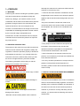
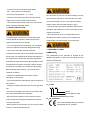
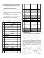
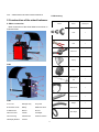
I
TABLE OF CONTENTS
1、 PREFACE
1
1.1 WARNING
1
1.2 RELATIVE INTRODUCTION
1
1.3 INSTALLATION ENVIRONEMNT REQUIREMENT
1
1.4 SAFETY REGULATION
2
1.5 MEANING OF LABEL
2
2、CARRIAGE, HOISTING, STORAGE, TRANSPORTATION AND INSTALLATION OF WHEEL BALANCERS 3
2.1 CARRIAGE & HOISTING
3
2.2 STORAGE & TRANSPORTATION
4
2.3 INSTALLATION
4
3 INSTALLATION OF EACH PART OF CB968 WHEEL BALANCER
5
3.1 PROTECTIVE COVER INSTALLATION
5
3.2 LCD AND ITS SUPPORT INSTALLATION
5
3.3 WIDTH SCALE INSTALLATION
6
3.4 THREAD THAFT INSTALLATION
6
3 .5 WHEEL IN STALLAT ION
6
3.6 POWER SUPPLY CONFIGURATION
7
3.7 NOTE WHEN INSTALLATION AND OPERATION
8
3 .8 IM PORTAN T R EMIND ING
9
4. CB968 TECHNICAL PERFORMANCE
9
4.1 CB968 CHARACTERISTIC
9
4.2 MAIN TECHNICAL PARAMETER
10
4.3WORK PRINCIPLE
10
5 STRUCTURE OF BALANCER
11
5.1 MAIN STRUCTURE OF BALANCER
11
5.2 BALANCER ACCESSORY CONFIGURATION
11
5.3 BALANCER OVERALL DIMENSION
12
6、MEANING OF ICONS
12
6.1 MODE SELECTION
12
6.2 SETUP MENU
13
6.3 HELP MENU
14
6.4 OTHER ICONS
14
7、 OPERATION MET HOD
14
7.1 JOYSTICK OPERATION
14
II
7.2 PARAMETER SELECTION AFTER STARTING THE MACHINE
15
7.3 WHEEL PARAMTER INPUT METHOD
16
7.4 USER SELF-CALIBRATION
19
7 .5 AU TO M AT IC SC AL E SEL F - C AL IBR ATIO N
19
7.6 WIDTH SCALE SELF-CALIBRATION
20
7.7 DYN/STA MODE OPERATION
20
7.8 ALU1 MODE
21
7.9 ALU2 MODE
23
7.10 ALU3 MODE
24
7.11 ALU4 MODE
25
7.12 ALU5 MODE
25
7.13 MATCH MODE OPERATION
26
7.14 WEIGHT HIDE FUNCTION
27
7.15 COUNTING
28
7.16 WEIDTH SCALE TEST PARAMETER FINE CALIBRATION
29
7.17 BALANCE SHAFT SELF-CALIBRATION
29
8、 EXWORKS PARAMETER BACK-UP AND RESTORE
31
8.1 EXWORKS PARAMETER BACK-UP
31
8.2 EXWORKS PARAMETER RESTORE
31
9、USE OS GREASE
32
9.1 GR EASING BAL ANCER
32
9.2 OIL SAFETY DATA SHEET
33
10、DAILY MAINTANENCE
33
11、TROUBLE ANALYSIS
34
12、ELECTRICAL SYSTEM DIAGRAM
35
13、WEARING SPARE PARTS LIST
36
III
and keep this manual on the document folder near the
1、PREFACE
machine for check at any time.
1.1 WARNING
* Technical document should be considered to be the
Confirming the machine including the operation system,
integrited part os the machine and it should be placed
tools and accessories are operated normally and
together with the machine when being sold to the new
without any damage, you hand the machine to the
owner.
cusatomers and the machine will endue some period of
*Only when the series nuimber and model of the
guranttee. During this period, the manufacturer will
manual are same to the series number and model on
repair the machine or the unnormal parts of the
the nameplate, the manual can be considered to be
machine or machine itself free of charge but will not be
effective.
responsible for the damage and wear and tear caused
by the unnormal usage, transportation and
maintanance. And the manufacturer will not notify the
customers when he renews the products or improves
the production line.
* Firmly keep in mind and follow the description and
1.2 RELATIVE INTRODUCTION
information of this manual at any time and the
The purpose of this manual is to provide the users and
operators should be responsible for the operatiuoins
owerners of this machine with the guide of safety and
not described and authorized in the manual.
regulation to make the operators properly maintanence
* Some information of the manual comes from the
and operates the machine. If you carefully follow this
pictures, it is normal that you will see some differences
instruction manual, the machine will provide you with
to the standard machines.
the service of higher efficiency and more durable.
* Do not try the other operations exc except under the
The following paragraphs will provide you with the
guidance of the personnels with experience. If
damage level relateed to the machine.
necessary, please contact with the authorized service
center for help.
Danger: operation can cause the serious injury or death
1.3 INSTALLATION ENVIRONMENT REQUIREMENT
Warning:operation can cause the serious damage or
The select of the installation site must be in accordance
unsafe
with the current effective safety regulation. We should
specially point out that the installation and operation of
the machine must have the anti-moisture protective
Caution: operation can cause slight wound and the
methods. If you want to correctly and safely use the
damage of the objects
machine, you should meet the following environment
*Read the manual carefully before use the machine
requirements:
1
- Luminosity in site should be at least 300lux
- RD:<85% (without condensation)
- Environment temperature:0°—+50°C
Do not remove or wear out any label os danger, caution
- The floor of the ground should be enough solid to
and warning or instruction. If the lable is lost or fuzzy,
support the maximum weight of the machine.
you should change it at once. If the label is missing,
- The machine should not be used in the environment
please contact with the nearest dealer to get it.
with the potential exploded factors
- See the accident precuation regulation related to the
1.4 SAFETY REGULATION
opertation and maintanence of the mechanism of high
voltage and rotation
- The manufacturer will not be respondible for the
* Not following the information and overlooking the
damage and accident caused by the changes and
warning labels will cause the series injuries to the
modifications not authorized by the manufacturer.
operators and the other personnels.
* You can operate the machines after you completely
read and understand the entire damages/warnings.
1.5 MEANING OF LABEL
* The correct use of the machine needs the
NAMEPLATE:
professional operator who must undertake the suitable
The nameplate of the machine is sticked at the
training and can understand the written descriptions of
middle top position on the rear of the body and the
the manufacturer, familiar with the safety regulations
meaning of them are:
and follow all these descrioptions and regulations. And
meanwhilem the operator should be a person without
bad habit and of healthy of mentality and physiology.
Before operating the machine, you must have the
following conditions:
- Read and understand the information and the
description in the manual
- Fully understand the characteristic and the features of
the machine
A、model
C B 968
- Keep the unauthorized personnels from the operative
site
- Be sure the installation should be in accordance with
model
wheel balancer code
wheel code
the current standard and the regulation
- Be sure that the operators os the machine should
B、CE Certificate
enbuce the proper training and operate the machine
correctly and safety.
This mark indicates that the machine
has passed the CE certified
- Before power off the machine, do not touch the cables,
motors or other electrical elements.
2
C、Serial number
It is the series number for applying the CE certificate.
POWER OFF THE ELECTRICAL
SOURCE OF THE MACHINE
DURING MAINTANCE
D、Other contents
The other contents of the nameplate includes the
technical parameters and the production date of the
machine .
2、CARRIAGE, HOISTING, STORAGE
AND TRANSPORTATION OF THE
WHEEL BALANCER
Lightning:
This label is at the rear of the machine or
on the surface of the electrical control
2.1 CARRIAGE & HOISTING
system indicating there is the connect of power supply.
Place, transport and store the machine according to the
Warn the operator care about the safety.
indication on the package container. When transport
and hoist the wheel balancer, do not make the
Rotation mechnism warning label:
accessory hang, weight tray, balance shaft and display
This label is sticked near the balance
cover to be the weight bearing area because this can
shaft to reminder the operator these are
cause the damage of the machine or the precision error
the rotation parts and are very dangerous and the
and even the injury to the operator. According to the
operators must not close or use hand to touch the
construction of the wheel balancer, the center of gravity
movable parts. The arrow indicates the rotation
is on the right off-center, therefore when lift the machine
direction of the rotation mechanism.
unpacked, thelift arm of the hydraulic vertical lift of the
forklift should be deflect to the right meaning not
Ground:
exceed 1/4 of the width of the machine. It is best to
This symbol lies near the earth wire
cover a layer of paper shell and rubber to avoid the
inside the machine to remind there is
slide of the machine. When lift and slide the machine,
earth wire and the operator must not detach or loose
there should be the personnel to hold the machine and
the earth wire.
the maximum height of lifting should not exceed one
meter. If exceeding one meter, you should fix the
ATTENTION:
machine properly.
If hoist the wheel balancer, you can pass the wide cloth
band through the clearance under the machine. The
WEAR PROTECTIVE GLOVE
cloth band must be 2 pieces or more than 2pieces and
the load bearing should be more than 500kg and the
length should be of same. The position of the cloth
band should be in accordance with the requirement of
READ OPERATION MANUAL
lifting the machine. When hoist, it is best that some
personnel to hold the machine. When lift or hoist the
machine, the speed should be not more than 35mm/s
for fear that the much inertia causing the slide and
WEAR PROTECTIVE GLASSES
3
fire source, dust, inflammable and explosive materials
swing of the machine to cause the dangeous.
and the chemicals. The floor should be flat and solid.
2.2Storage and transportation
Storage:The machine should not be exposed and
should be covered with the plastic film. For the pile of
the vertical tyre changer, it should be 3layers is the
paper package and it is 4 layers if it is in the wood
package. And for the pile of the horizontal tyre
changer in the wood package, it should be 3layers.
And all the models should not be placed upside
down.The should be stored in the warehouse of
ventilation, dry and waterproof. In the storage area,
the temperature should be controlled in the range of
-10 ℃~ 55℃ and RH should be controlled in the
range of 30% ~ 90%. It is forbidden to store the
machine together with the dangerous chemical, the
inflammable and explosive materials or the objects
easy to born the dust.
Transportation: The load of the machine should be
accordance with the indication on the outer package
and fix firmly. No matter what kind of transportation, the
environment temperature and humidity should comply
with the requirement of the storage requirement
specified in term2.2. In the process of transportation,
you should avoid the drench by rain, solarization、
Before installation, detach the upper cover of the
dumpage or collide. It is forbidden transport the
package box of the wheel balancer and confirm the
machine together with the dangerous chemicals,
machines, accessoriues shipped together with the
inflammable and explosive materials or the objects
machine and the data you purchase according to the
easy to born the dust.
packing list. If you have any question, you can contact
with the dealers.
The packing material such as plastic, polystyrene, nail ,
2.3 Installation
screw, wood and the carton must be placed into a scrap
After confirming the package of the wheel balancer
box and handle according to the local law and
intact, you can carry the machine to the installation
regulation. When install, detach the connect bolt
area as shown in the Fig1
between the wheel balancer and the pallet of the
Environment requiremnent at the installation site :
package box and move the machine from the pallet to
Temperature 0℃-50℃,RH≤85%, without water source,
the installation position. To guarantee the safety and
4
fast os the operation, there should be the distance
more than 300cm from the wall of the building to the
right and rear of the machine. And the distance of more
than 200cm from the wall of the building to the left of
the machine as shown in FIG2. After the wheel
balancer is moved to the proper posiotion, drill 3 abchor
holes on the ground according to the installation hole at
the foot of the machine and then use 3 pieces of
M10X160 anchor screws to fix the machine on the
ground to guarantee the stability and reliability of the
machine.
3、Installation of the each part of
CB968 wheel balancer
FIG 3
Before install and use the wheel balancer, please
Pass the installation bracket of the protective cover
carefully read this installation and operation manual
through the rotation shaft of the protective cover on the
and keep this manual in hand for the check at any time.
body of the machine. When passing through, pay
Be sure that all the users have read this manual to
attention that the installation hole on the installation
exert the best performance of the machine to
bracket of the protective cover should be aligned to the
guarantee the safety.
installation hole on the rotation shaft and then pass
through 2pieces of M10X50 screws. Then use the
Note:
locknut to completely lock. And the angle of the
protective cover has been calibrated well.
3.2Installation of the display and the support
Wear
Read the
Wear the
When
protective
manual
goggle
repair, be
glove
carefully
sure the
before
power
operation
source is
nM10X35screws, 4 plain washers and 4 elastic
switched
washers to fix the display installation bracket on the
off
wheel balancer body and then use 4pieces of M4X12
bracket of the display
After check the installation braqcket of the display and
the display are normal, first use 4 pieces of
screw to fix the display on the display installation
3.1PInstallation of the protective cover
bracket. If need pitch angle adjustment, you can loose
Before use the machine, you need to install the
the 2pieces of M5X12 lock screw at the connect
protective cover. Please connect the protective cover
position of the display installation board and the rotation
as shown in FIG 3.
shaft to adjust. After adjustment, relock. If need to
adjust the height of the display and the left/right angles,
5
you can loose3pieces of M8X12 lock screw on the
3.4 Installation of the thread shaft
chassis of the display installation bracket to adjust.
Before installation, use the alcohol or compressed air to
After adjustment, relock the screw as shown in the
clean the rotation shaft of the balancing shaft anf the
FIG4.
center hole of the thread shaft. Plug the open end of the
thread shaft into the rotation shaft of the balancing shaft
until the end of the thread shaft completely be
contacted with the contact surface of the balancing
shaft. Turn clockwise to tight. When tight, use the
screwdriver or the other auxialiary tools to plug into the
auxialiary hole to help the tight as shown in FIG6.
FIG 4
FIG 6
3.3Installation of the width scale
After check the width scale is normal, use 3pieces of
3.5 MOUNT WHEEL:
M10X40 screw and 3 pieces of spring washer to fix the
Check and clean the dust and mud and if there are
width scale on the wheel balancer body. When fix, pay
foreign bodies, such as metal, stone, clipped weights
attention that the fix of the width scale bracket should
on the surface of the tyre or wheel. And also check the
be
air pressure of the tyre is according with the specified
horizontal
and
firm
and
then
connect
the
value. Check if there are deformation on the rim
potentiometer cable of width scale and the extension
positioning surface and installation hole.
cable in the body as shown in FIG5.
The installation methods of the wheel : Positive
positioning, negative positioning & flange disk. You can
select different methods according to the practice.
3.5.2 SMALL CAR WHEEL POSITIVE POSITION
Positive positioning is the normal method. It is featured
with simple and quick operation. It is mainly suitable to
the common steel rim and aluminum alloy rim with
small deformation.
FIG 5
6
Main shaft
main shaft)
large flange plate(fixed on the
wheel
cone
quick nut
Note:The choice on the cone should be adapted to the
rim center hole and pay attention to its direction. Or it
will cause the inaccurate measurement.
3.6 Configurate the power supply
Main shaft
wheel( direction of the rim installation
surface is inside)
cone
quick nut
3.5.3 SMALL CAR WHEEL NEGATIVE POSITION
* The machine must be grounded reliable or it will effect
the test accuracy and the anti-interference power!
* Power supply must comply with the reate parameter
of the machine!
* The electerical installation of themachine must be
handled by the authorized professional personnels!
3.6.1 Circuit Requirement
Before layout the wires, you must confirm the electrical
parameters. The power supply supplied by the
Main shaft
spring
bowl
quick nut
cone
wheel
customers must match the rated electrical parameters
of the machine.When the users use the machine, he
When the deformation of the outside of the wheel,
can not dirtectly connect the power cable into the
adopt this method to positioning to grantee
electrical circuit. It should equip with the special
the
accurate positioning of the steel rim inner hole and
protective circuit suitable to prevent the ddamage to the
main shaft. suitable to the steel rim, especially the
machine for the unnormal electriucal circuit. Generally,
thick ALU
we should select the 10A circuit breaker two pole or
3.5.4 LARGE FLANGE DISK POSITION(OPTIONAL)
3pole. If use the greater circuit braker, you should equip
This position is adapted to the mount of the large tire.
the fuse in the circuit. The metal cross section of each
lead power supply circuit should not lass than 1.5mm2
and the earth wire should be 1.0mm2. You can choose
the oil-resistant cable 3-core or quard which is
off-contact or in conduit. You can also adopt the one
perfect insulated layer cable which is laid in the channel
or inserting into the pipe. If there are always the
equipments, vehicles or the personnels in/off or the
work environment is no good, the power cable should
7
be pipe laying or off-contact.
3.6.2Requirement of the power supply
The voltage of the power supply should be stable and
* Do not keep the machine in the environment of
the circuit should have some capability of overload. The
extremely humidity and temperature. Avoid being
fluctuation of the voltage should not exceed 5% of the
installed near the heater, waterhead, air humidifier and
rated voltage and the fluctuation of the frequency
stove.
should not more than 1Hz. Or we should sdd the
*Do not install the wheel balancer in front of the window
frequency/ voltage stabilizer at the power supply
directly under the sunlight. If this situation can not be
position to keep the stable of the voltage and frequency.
avoided, use the shield.
* Prevent the wheel balancer from the large quantity of
3.6.3Socket requirement
dust, alcohol, ammonia gas, diluent and spray.
All the car wheel balancer will be equipped with the
* When use the machine, unauthorized personnel
power cable and plug when ex-work and the customer
should not close to the machine.
directly adapt the socket match the plug. But the socket
* Before move the machine, you should contact with
must follow the following requirements:
your personnel of repair and service.
ⅠRated capacity of the socket should exceed 500VA
* When the weight of the wheel exceed 15kg,you
and the rated current shoulkd be more than 10A;
should use the auxialiary lift and vertical device.You
Ⅱ Socket must have the reliable earth wire and should
can not directly use your hand to lift the wheel to avoid
not use the two-pole socket without earth wire for
the injury to your body.
without earth wire will influence the accuracy and
* Before use the wheel balancer, you must use the
interference power of the machine. The earth wire of
anchor screw to fix the machine on the ground.This fix
the machine should be connected with the special earth
should be the 3-point –fix or the vibration of the
wire and can not be connected with the water pipe and
machine when operation can cause the inaccuracy of
oil pipe.
the test result, especially the tire with the height more
Ⅲ Socket should be the socket with switch to power off
than 35kg.
the machine when the equipments are abnormal or no
* When the machine is in the process of operation,
use of the machine.
there should no the other electreonic or high power
Ⅳ The connect between the plug and the socket must
device interferring the machine and influencing the
be reliable.
accuracy.
Ⅴ It is better to use the special socket to supply the
*Proper dressing such as glove, goggle and work suits.
power to the machine and can not connect many
Not wear necktie, long hair,loose clothing
devices.
or the sandal. When operation, the operators should
3.7 Note for the installation and operation of the
stand beside the machine and unauthorized
machine
personnel should not close.
*When the illumination in the working site is not well,
prepare the illumination device. Coomon dylight lamp
8
or incandescance lamp is OK. It is no need too light.
* Before balancing the wheel, operators should check
The brightness should be such that will not influence
all the wheels to see if there is any fault. Do not balance
the work.
the wheel with fault.
*Do not try to balance the tire heavier than the standard
design of the machine.
3.8Important Note
*Before balancing, be sure the installation of the wheel
should be properly.
* Periodically maintanence the machine.
* Do not look at the laser point directly in any case.
4、CB968 Technical Characteristic
* Before operation, the operator should carefully read
4.1 CB968 Feature:
all the warning ladels and manual to avoid the injuries
- Adopt the LCD and the display is compltely and
and damage to the operators or bystanders.
straight and the picture is clear and vivid
*Machine should be firmly fixed on the ground. Avoid
-Use the joystick to replace the traditional press key
installing the machine near the compressor.
and the customer need not memory the functions of the
*Do not detach the the protective cover.
relative press button to make the operation more
*Do not detach or modify the machine by yourself.
convenient and faster.
*Prvent the rotation shaft of the balance shaft from
-All the operation steps are equipped with the
being impacked.
indications of animation and words to make the
* After switch off the machine, wait for 5seconds and
operation more direct and precisely to avoid the
then you can use the machine again.
misoperation.
* Do not place too much heavy objects on the console
-The main control system all adopt thr quality
of the wheel balancer.
computer components with the features of high stability
* If fault and the machine can not operated, please
and high intelligence.
check the relevant contents. If unormal noise, smog or
-The mechanical main shaft adopts the high precise
the other phenomenons suddenly, you should switch off
bearing driven with the feature of high precise,
the machine and pull out the plug and notify the
anti-wearance and low noise.
relevant service personnel.
-For the realization of the automatic measurement of
* If the function is not specified in the manual, you
the size of the wheel and the laser position of the
should not apply.
unbalance value, the test result becomes more
* Hand and any part os the body must not close to the
accurate.
rotation mechanism or the electrical connect. Before
-Laser positioning can accurately indicate the
run the machine,you should check if there are
unbalance position.
damaged parts. Or you should not use the machine if
-Intelligent automatic calibration and the electreonic
there is any broken and cracked.
scale automatic marking functions
* In the emergency, if the wheel is not firmly locked and
-The special functions of automatic tire counter, data
shake. Please press down the wheel balancer to stop
back-up management and the balance shaft
the machine.
9
related
self-calibration make the test more accurate and the
to
machine management and follow-up service more
weight
convenient.
os
-With 5 ALU modes and MATCH mode
wheel
-With the functions of full automatic disgnosis and self
16
Max. spin speed
210r/min
calibration.
17
Accuracy
±1g
18
Max. wheel width
20″
-Adopts the computer on/off power source to widen
Max.
wheel
47″
the voltage range
19
-Self-calibration and full automatic diagnosis
20
Rim diameter
10″~25″
-High integrated and memory make it convenient to
21
Rim width
1.5″~20″
expand the relative functions and upgrade.
22
Max. wheel weight
75kg
Diomension(after
1120X710X1180
packed)
(LXWXH)
Weight of machine
163kg
23
4.2MAIN TECHNICAL PARAMETERS OF THE
24
PRODUCTS
No
1
Technical
Item
Parameter
Rim suitable
3
Balance mode
4
Driven
6
7
8
9
10
11
12
26
Electrical-driven
Distance
&
diameter measure
width
measurement
Standard
conversion
equippment
/
≤85% at 40℃
27
Noise
≤70dB
28
IR
≥20MΩ
29
Total Power
300W
operators can execute the balance operation. When
automatic
gram/ounce
Self-diagnosis
20℃ 、
it checks each unit in the normal situation. And the
balancing, MCPU can control the rotation of the main
shaft of balancer tester through the drive interface. The
unbalance signal sensed by balance sensor is sent to
the micro-processor port through A/D converter. CPU
equippment
Self-calibration
at
The micro CPU will provide the normal information if
automatic
Standard
conversion
≤95%
4.3 WORK PRINCIPLE
equippment
mm/inch
0~50℃
50Hz
Standard
Hood on/off
environment
humidity
ALU modes
220V
environment
Working
match、Dyn、Sta、5
frequency
NT
temperature
Car and light truck
Rated voltage and
wheel
25
Remark
alloy rim
Vehicle suitable
diameter
Working
Aluminum, steel and
2
5
the
will integrated analyze the unbalance signal and angle
signal to calculate the unbalance value and display the
value through the LCD unit. We can realize the
Standard
man-machine talk through joystick and LCD as shown
equippment
in FIG7..
Standard
error display
equippment
13
Brake
Automatic /manual
14
Display
LCD
15
Cycle
7s ( 16″ standard
Cycle is
rim)
not
10
FIG7 CB968 WHEEL BALACER WORK PRINCIPLE
5.2Accessory
5 Construction of the wheel balancer
Picture
5.1Main constuction
Name
Quantity Pc
Cone
1
Pliar
1
Quick Nut
1
Spring
1
Bowl
1
Main construction of the wheel balancer as shown in
FIG8 and FIG9:
FIG8
self-calibration
tool
1
Width Scale
1
Thread Shaft
1
Weight
1
Bowl Edge
1
FIG9
1.15" LCD
2.Weight Tray
3.Joystick
4.Automatic Scale
5.Body
6.Balance Shaft
7.Width Scale
8.Hood
9.Cone
10.Front Panel
11.Pliar
12.Caliper
13.Cone Hang
14.Quick Nut
15.Power Switch
16.Display Bracket
17.Seat
11
Hood
1
Centerless Rim Calipter
Optional Accesory
Picture
DK-W-2
Name
MJ-I I
5.3Outline Dimension
As shown in Fig 10 and Fig11:
Fig11
Large Cone
Weight stick Ruler
DK-W-1
Fig10
MJ-I
4-hole Adaptor
Fig11
Flange Disk
6. Meaning of icons
6.1 Mode selection bar:
The mode selection bar is at the top of the screen.
12
Move the joystick to the left or right, you can choose the
rim.After test, clip the weight on edge inside the rim and
mode you need. When the mode has been delected,
stick the weight on the calibration surface near the
the mode selected will be enlarged and the edge will
spoke inside the rim.
become green and light as shown in the FIG12.
ALU4 mode:After select the icon, it
means that the weight calibration surface
FIG12
is located on the edge of the inside of the
rim and the calibration surface near the spoke inside
the rim.After test, clip the weight on edge inside the rim
Instruction on each mode bar
and stick the weight on the calibration surface near the
spoke outside the rim.
DYN/STA
mode
icon:means
the
current system mode is dynamic/static mode. The
ALU5 mode:After select the icon, it
default mode is the dynamic balancing mode. The
means that the weight calibration surface
balance weight calibration surface is at the edges on
the both sides of the rim. After test, clip the weight on
is located on the edge of the inside of the
the calibration surface on both edges of the rim. If you
rim and the calibration surface near the spoke inside
want to check the unbalance value, you can only move
the rim.After test, stick the weight inside the rim and clip
the joystick upwards, And move the joystick upward
the weight on the edge outside the rim.
once again, you will back to the dynamic mode.
Match mode: Choosing this mode can
ALU1 mode: After select the icon,
match the static value of the tire and the rim to make
it means that the weight calibration surface is located
the static unbalance value to reach the minimum value.
on the two calibration surface inside and outside the rim.
After test, stick the weight on the two calibration
System setup mode: After choosing the
surface.
icon, move the joystick downward to
enter the system setup menu. At this time,
a password input column will come out. Move the
ALU2 mode:After select the icon,
joystick rightward, downward and upward and then
it means that the weight calibration surface is located
input the passward of 111. Press down the joystick to
on the two calibration surface inside the rim. As shown
confirm and enter the menu selection.
of the picture in the left, after test, stick the weight on
the two calibration surface inside the spoke.
Help Info: After choosing this icon, move
the joysticks downward to help enter the
page of help. The current mode of the
ALU3 mode:After select the icon,
system is static mode.
it means that the weight calibration
6.2Setup menu
surface is located on the edge of the inside of the rim
The setup menu is located in the bottom of the screen,
and the calibration surface near the spoke inside the
13
when choode
6.4Other icons
menu , The setup menu will
Display the wheel size parameters such
appear at the bottom of the screen. Move the joystick
as A、B(or A+)
、D.
downward, you can enter the select of the system setup
menu. If it is the first time to enter the system setup
menu after start up, the passward input column will
come out. Move the joystick rightward, downward and
In the MATCH mode, display the static
upward and then input the passward of 111. Press
weight. From the top to the botom, it
down the joystick to confirm and enter the system setup
displays the static weight of the rim and
menu. You do not need to input the password if enter
tyre. After match, the wheel can reach the
again without turn off the machine. The function of the
minimum static weight.
system setup manu as shown in FIG13.
FIG 13
When the system display the unit of the
weight is gram, it will remind the
customer to clip the standard weight of 100g when
self-calibration.
When the system display the unit of the
weight is ounce, it will remind the
customer to clip the standard weight of 3.5ounce when
self-calibration.
6.3Help Menu
Help menu is at the bottom of the screen. After
select
7、Operation of the wheel balancer
menu, the help menu will appear at
7.1Operation of the joystick
the bottom of the screen. Move the joystick
downwards to enter the selection of the help menu.
Move the joystick leftward:
The function of the help menu is as shown in FIG
Exit from the current status;
14.
Select the icons leftside;
Decrease the input value when
input the related parameters
Move the joystick rightward:
Select the icons lrightside;
Increase the input value when
input the related parameters
FIG14
14
Move upward the joystick:
illuminate. Move the joystick downward to enter the
Enter into the wheel parameter
help menu and move the joystick rightward to select the
input status in the mode menu.
language selection icon and at the moment the
In the AUL2、AUL3 mode, after
language selection column will appear as shown in the
the wheel test,move upward the
FIG15. Move the joystick upward or downward or
joystick
upward to select the language you want to choose and
to
enter
the
split
press down the joystick to confirm.
function;
When the selection column,Move the joystick upward
Note : If not select the language, the default
to return to the mode selection.
language is English.
After complete the wheel test in the DYN/STA mode,
move the joystick upward for one time, you can change
7.2.2 Unbalance unit selection
from dynamic to the static and upward once more you
After start the machine, you can enter the mode
can change from the static to the dynamic.
selection menu. In the mode selection menu, you can
select
menu. The icon will be enlarge and
Move downward the joystick:
illuminate. Move the joystick downward to enter the
In the balance mode menu,
system setup menu and move the joystick rightward to
enter the wheel parameter
select unbalance unit display option and at the moment
input status;
the unbalance unit display column will light up. Move
After finish the wheel test,
the joystick upward or downward to realize the
move downward the joystick to check the real
conversion between the g and OZ as FIG 16 shown.
unbalance weight of the wheel;
After select the unit you want and press down the
When in the system setup mode, move downward the
joystick to confirm.
joystick to enter the system setup menu.
Note: If not select, the system defualt unbalance
unit is g.
FIG 15
Press down the joystick:
Confirm the status;
Wheel balancer run;
Emergency stop when
running.
7.2 Parameter selection after start up the machine
7.2.1Language selection of the operation interface
After start the machine, you can enter the mode
selection menu. In the mode selection menu, you can
select
menu. The icon will be enlarge and
15
FIG 16
7.2.3Minimum unbalance weight display setup
confirm as shown in the FIG18.
Select the
menu in the mode selection menu
Note:If not select, the system default protective
and the icon will enlarge and light up. Move the joystick
cover is on. When lower the proitective cover to the
downward to enter the system setup menu and move
specific
the joystick rightward to select the minimum weight
automatically and when choose off, you need adopt
display option and at the momnent the selection item
the manual way to start spin.
position,
the
machine
will
spin
will appear as shown in FIG17. Move the joystick
upward or downward to select the suitable option and
7.3 Wheel parameter input method
press down the joystick to confirm.
7.3.1 Manual input the wheel parameter
Note: If not select, the system defualt minimum
The wheel parameter measurement is normally
unbalance unit display is 5g.
automatically through the automatic scale and width
FIG17
scale. Of cause you can also manual input various
parameters of the wheel. The manual input is select the
operation
mode
and
then
move
upwards
and
downward the joestick to select the parameter you want
to select and move rightward or leftward to decrease or
increase the parameter value. After input, press down
the joystick to confirm.
7.3.2 utomatically measure the wheel parameter
We can aitomatically measure the value of A, A+, D and
FIG18
B through the automatic and width scales. When
measure, first pull out the automatic scale to make the
laser point fall at the calibration surface of the weight
and then rotate the automatic scale to make the laser
point fall at the horizontal projection of the laser ray.
About 2seconds later, the value of A(or A+)and D will
be input automatically and the aitomatic scale will be
retrack to its home position. The measurement of the
value of B is automatically through the width scale.
Rotate the width scale until it reach the calibration
7.2.3Protective cover setup
Select
surface of the weight and about 2seconds later, the
menu in the mode selection menu and
value of B will be input and retaract the width back to
the icon will be enlarged and light up. Move downwards
the
home
position
after
measurement,
The
the joystick to enter the system setup menu and move
measurement position of automatic and width scale in
backwards the joystick to select the protective cover
each mode are as shown in the follows.
function. At the moment, the icon of the protective
cover function will be enlarged and light up. Move
upward and downward the joystick to select the on or
off os the protective cover. Press down the joystick to
16
In DYN mode, we
needmeasure
the
parameters of A, D
and B.
In ALU1 mode, we
need measure the
parameters of A, D
and B.
In ALU2 mode, we
need measure the
parameters of A、A+
and D.
In ALU3 mode, we
need to measure the
parameter of A, A+
and D.
17
In ALU4 mode, we
need to measure the
parameter of A, D and
B
In ALU5 mode, you
need to measure the
poarameter of A 、 D
and B
In MATCH mode,
youneed to measure
the parameter of D
18
FIG 19
7.4Customer self-calibration
Select the
FIG 20
menu in the mode selection menu
and the icon will be enlarged and light up. Move
downward the joystick to enter the system setup menu
and move backward the joystick to select the customer
self-calibration icon and the icon will be enlarged and
light up as shown in FIG19. Move downward the
FIG22
joystick to confirm and the machine will enter the
FIG 21
customer self-calibration interface as shown in FIG20 in
which the customer can complete the self-calibration
according to the pictures on top and the words on the
left in the customer self-calibration interface. The
instruction to the detailed steps are as follows:
Fix the wheel for self-calibration
Press down the
FIG 24
FIG 23
joystick for 2times to enter the parameter input as
shown in FIG21
Use the automatic scale to
measure the value of A and D and use the width scale
to measure the value of B
Lower down th
eprotective cover and the machine runs
After
the end of the running, rotate the wheel until the angle
indicator ouside change from green triangle to the
thumb and stop as shown in FIG22.
Clip the
press down the joystick to
standard weight of 100g at the 12clock position outside
complete the customer
Lower down the protective cover to run the
self-calibration and enter
the interface of balancing
machine
After the stop of the run, rotate the wheel until
7.5Automatic scale self-calibration
the the angle indicator inside change from green
Select
triangle to the thumb and stop as shown in FIG23.
menu in the mode select menu and the
icon will be enlarged and light up. Move downward the
Clip the standard weight of 100g at the 12clock
joystick to enter the system setup menu and move
position inside
rightward the joystick to select the automatic scale
Lower down the protective cover and the
self-calibration icon which will be enlarged and light up
machine runs
as FIG25 shown. In the interface of automatic scale
After the running stops, press down the joystick
self-calibration, there are the indication of the picture.
to complete the customer self-calibration and enter the
You can complete the automatic scale according to the
interface of balancing the wheel as the FIG24 shown.
instruction and the detail steps are as follows:
Pull the scale to the position of 5cm and press down the
19
FIG 27
joystick to confirm as the 1st step of FIG 26 shown
FIG 28
Pull the scale at the position of 20cm and press down
the joystick to confirm as the second step of the FIG26
shown
accessory
Install the D value self-calibration
Point the laser point to the base
line,Press down the joystick tp confirm as the 3rd step
and 4th step of FIG26 shown and press the joystick to
confirm and the self-calibration completes.
7.7 DYN/STA mode operation
After self-calibration, the system will automatically
7.6Width scale self-calibration
Select
enter into the wheel balance operation interface and
menu in the mode select menu and the
the default mode is DYN/STA mode. The detailed
icon will be enlarged and light up. Move downward the
operation process of DYN/STA mode is as fillows:
joystick to enter the system setup menu and move
Fix the wheel on the main shaft of the wheel balancer
rightward the joystick to select the width scale
Pull out the automatic scale and the spot laser
self-calibration icon which will be enlarged and light up
and the linear laser will automatically light up. Align the
as FIG27 shown.Press down the joystick to enter the
projection of the spot laser to the projection of the linear
width scale self-calibration interface. In the interface of
laser and hold on, Retract the automatic scale when
width scale self-calibration, there are the indication of
hearing the warning tone of the complete of the test
the picture. You can complete the width scale according
and the measurement of A value and D value as FIG29
to the instruction and the detail steps are as follows:
shown
Pull the width scale to the top of the thread shaft and
Lean the end of the measurement head of the width
press down the joystick to confirm as the 1st step of
FIG28 shown
scale against the outside edge of calibration surface
Pull the width scale to the
and hold on and retract the automatic scale when
surface of the insulation seat near the rim and press the
hearing the warning tone of the complete of the test
joystick to confirm as the 2nd step of FIG28 shown
Place the width
and
scale to the home position
measurement of
B
as
FIG30
shown
Press down the joystick or lower down the protective
and press down the joystick to confirm as the 3rd step of
cover to test as FIG31 shown
FIG28 shown
After test, the
system will automatically display the value and position
self-calibration completes
FIG 25
the
of the wheel unbalance weight. Move the joystick
FIG 26
downward to check the accuracy as FIG32 shown
Along the direction of the green direction of the
inside/outside unbalance indication arrow, rotate the
wheel until the green triangle arrow is changed to the
thumb,Clip the weight at 12 clock position and the
value should be corresponding to the test value as
FIG33 shown
After the inside/outside weight are
clipped, retest the wheel.
20
If the test result meet
FIG 32
the requiremnent, the test comnplete and demount the
wheel, If the test result does not meet the requirement,
retest and calibrate until meet the requirement.。
In the dynamic mode, if you want to change into the
static mode,you only need to move upward the joystick
after getting the dynamic balance test result . In this
case, you can change into the static balance mode.
And the system will automatically change from the
FIG 33
dynamic unbalance value into the static unbalance
value. The only thinf needs the operator do is to stick
the weight according to the display value as FIG34
shown.
FIG 29
FIG 34
FIG 30
7.8 ALU1 mode
Select the ALU1 mode in the mode select menu,the
system will automatically enter the ALU1 mode
operation interface. The detailed operationa steps of
ALU1 mode are as follows:
FIG 31
Fix the wheel on the main shaft of the wheel balancer
Pull out the automatic scale until reach the
inside calibration surface of the rim. Align the projection
of the spot laser to the projection of the linear laser and
hold on, Retract the automatic scale when hearing the
21
FIG 36
warning tone of the complete of the test and the
measurement of A value and D value as FIG35 shown
Lean the end of the measurement head of the width
scale against the outside edge of calibration surface
and hold on and retract the automatic scale when
hearing the warning tone of the complete of the test
and the measurement of B as FIG36 shown
Press down the joystick or lower down the
protective cover to test as FIG37 shown
FIG 37
After
test, the system will automatically display the value and
position of the wheel unbalance weight. Move the
joystick downward to check the accuracy as FIG38
shown
Along the direction of the green direction
of the inside/outside unbalance indication arrow, rotate
the wheel until the green triangle arrow is changed to
the thumb,Clip the weight at 12 clock position and the
value should be corresponding to the test value as
FIG39 shown
FIG 38
Pull out the automatic scale when
the speed should not too fast or it will not reach the
selection position and need the further adjustment. The
electromegnic iron will automatically streach out when
the scale reach the selected position. Along the
direction of the green direction of the inside/outside
unbalance indication arrow, rotate the wheel until the
green triangle arrow is changed to the thumb. The laser
point on the automatic scale will indicate the weight
stick position and stick the weight
FIG 39
on the rim
according to the indication of the laser as FIG 40 shown
Retest the wheel.
If the test result meet
the requiremnent, the test comnplete and demount the
wheel, If the test result does not meet the requirement,
retest and calibrate until meet the requirement.。
FIG 35
22
FIG 40
automatic scale when the speed should not too fast or it
will not reach the selection position and need the
further
adjustment.
The
electromegnic
iron
will
automatically streach out when the scale reach the
selected position. Along the direction of the green
direction of the inside/outside unbalance indication
arrow, rotate the wheel until the green triangle arrow is
changed to the thumb. The laser point on the automatic
scale will indicate the weight stick position and stick the
weight according to the method of the ALU1 mode
7.9 ALU2 mode
Continue
Select the ALU2 mode in the mode select menu,the
pulling the automatic scale with more
system will automatically enter the ALU2 mode
force making ther electromegnic iron detached until
operation interface. The detailed operationa steps of
reaching the second selection position (A+).The
ALU2 mode are as follows:
electromegnic iron will automatically streach out to
Fix the wheel on the main shaft of the wheel balancer
position the scale. Along the direction of the green
Pull out the automatic scale until reach the 1st
direction of the inside/outside unbalance indication
selection position inside the rim. Align the projection of
arrow, rotate the wheel until the green triangle arrow is
the spot laser to the projection of the linear laser and
changed to the thumb. The laser point on the automatic
hold on, Retract the automatic scale when hearing the
scale will indicate the weight stick position and stick the
warning tone of the complete of the test and the
weight according to the method of the ALU1 mode as
measurement of A value and A+ value as FIG41 and
shown in FIG 45 & 46
FIG42 shown
If the test result meet the requiremnent, the test
Press down the joystick or lower down the protective
comnplete and demount the wheel, If the test result
cover to test the wheel as FIG43 shown
does not meet the requirement, retest and calibrate
After
until meet the requirement.。
the test, the system will autometically display the value
and position of the unbalance weight as shown in
FIG44
FIG 41
Press down the joystick or lower down
the protective cover to test as FIG37 shown
After test, the system will automatically display
the value and position of the wheel unbalance weight.
Move the joystick downward to check the accuracy as
FIG38 shown
Along the direction of the green
direction of the inside/outside unbalance indication
arrow, rotate the wheel until the green triangle arrow is
changed to the thumb,Clip the weight at 12 clock
position and the value should be corresponding to the
test value as FIG39 shown
Pull out the
23
Retest the wheel.
FIG 42
FIG 46
FIG 43
7.10 ALU3 mode
Select the ALU3 mode in the mode select menu,the
system will automatically enter the ALU3 mode
operation interface. The detailed operationa steps of
ALU3 mode are as follows:
Fix the wheel on the main shaft of the wheel balancer
Pull out the automatic scale until reach the 1st
selection position inside the rim. Align the projection of
the spot laser to the projection of the linear laser and
FIG 44
hold on, Retract the automatic scale when hearing the
warning tone of the complete of the test of the
measurement of A value and then pull the scale to the
2nd position A+ and retract the automatic scale when
hearing the warning tone of the complete of the test of
the measurement of A+ value
Press down the
joystick or lower down the protective cover to test
After test, the system will automatically display the
value and position of the wheel unbalance weight.
FIG 45
Along the direction of the green direction of the
inside/outside unbalance indication arrow, rotate the
wheel until the green triangle arrow is changed to the
thumb,Clip the weight at 12 clock position and the
value should be corresponding to the test value
Pull out the automatic scale .The electromegnic
iron will automatically streach out when the scale reach
the second position(A+). Along the direction of the
green
24
direction
of
the
inside/outside
unbalance
indication arrow, rotate the wheel until the green
wheel, If the test result does not meet the requirement,
triangle arrow is changed to the thumb. The laser point
retest and calibrate until meet the requirement.
on the automatic scale will indicate the weight stick
position and stick the weight according to the method of
7.12 ALU5 mode
Select ALU5 mode in the mode select menu and
the ALU1 mode and place the automatic scale to the
home position
Retest the wheel.
the system automatically enter ALU5 mode
If the
test result meet the requiremnent, the test comnplete
test interface. The detailed operation steps of ALU5
and demount the wheel, If the test result does not meet
mode are as follows:
Fix the wheel on the main shaft of the wheel balancer
the requirement, retest and calibrate until meet the
firmly.
requirement.
Pull the automatic scale to the suitable
position inside the rim. Align the projection of the spot
laser to the prjection line of the linear laser and hold on.
7.11 ALU4 mode
Select the ALU4 mode in the mode select menu,the
Retract the automatic scale when hear the warning
system will automatically enter the ALU4 mode
tone and complete the measurement of the values of A
operation interface. The detailed operationa steps of
and D
ALU4 mode are as follows:
scale against the calibration surface outside the rim and
Pull the measurement head of the width
Fix the wheel on the main shaft of the wheel balancer
hold on and retract the width scale when hear the
Pull out the automatic scale and the spot laser
warning tone to complete the mesurement of the value
and the linear laser light up automatically. Align the
B
projection of the spot laser to the projection of the linear
protective cover to test.
laser and hold on, Retract the automatic scale when
system will display the position and the value of the
hearing the warning tone of the complete of the test of
unbalance weight.
the measurement of A and D value
Lean the
green triangular, rotate the wheel until the triangle
end of the measurement head agginst the outside of
changes into the thumb. At this moment, clip the
the rim and hold on and retract the width scale when
suitable weight at the 12clock position on the
hearing the warning tone of the complete of the test of
calibration surface outside the rim
the measurement of B value
Press down the
automatic scale and when the scale reaches the
joystick or lower down the protective cover to test
selected position, the electromagnet iron will dtrech out
After test, the system will automatically display the
automatiucally to position the automatic scale. Along
value and position of the wheel unbalance weight.
the direction of the green triangular, rotate the wheel
Along the direction of the green direction of the
until the triangle changes into the thumb. The head of
inside/outside unbalance indication arrow, rotate the
the automatic scale will point to the weight stick
wheel until the green triangle arrow is changed to the
position , stick the suitable weight according to the stick
thumb,Clip the weight at 12 clock position and the
method of ALU1
value should be corresponding to the test value
the test result comply with the requirement, demount
Retest the wheel.
If the test result meet the
the tire and the test complete. And retest until comply
requiremnent, the test comnplete and demount the
with the requirement if the test result are not comply
25
Press down the joystick or lower down the
After the test, the
Along the direction of the
Pull out the
Retest the wheel
If
unbalance as shown in the FIG52 and FIG53
with the requirement.
Along the direction of the green triangular,
rotate the wheel until the triangle changes into the
7.13 MATCH mode
When the static unbalance is overweight (more than
thumb. At this moment, mark at the 12clock position on
50g ), you can use the MATCH function to match the
the tire as shown in FIG 53 the suitable weight at the
unbalance position of tire and rim to decrease the
12clock position on the calibration surface outside the
weight. The work principle are as FIG47.
rim.
Demount the wheel and deflate and then
mount on the tire changer. Align the mark on the tire to
the nozzle of the rim as shown in FIG54
FIG 47
Once
again, mount the wheel on the wheel balancer and
press down the joystick and the screen will display the
current and mount the wheel on the wheel balancer
MATCH
again. Press down the joystick to run the wheel
balancer and the screen will display the current static
unbalance value and the ideal minimum static
unbalance weight. And the word indication column willl
indicate the success of the wheel match.
MATCH operation step:
Fix the wheel on the main shaft of the wheel balancer
FIG48
Measure the diameter of the wheel as shown in FIG48
Press down the joystick or lower down the
protective cover to test.
Rotate the nozzle of the
tire to the 12 clock position and hold on the wheel and
press down the joystick to confirm.
Align to the
nozzle and mark at the 6clock position on the tire as
shown in FIG49.
Demount the tire and deflate
and then mount on the tire changer. Rotate the related
position of the tire to the rim by 180degree that means
FIG 49
the mark on the tire aligned to the nozzle as shown in
FIG 50.
Inflate the tire and then mount the tire
on the wheel balancer and press down the joystick or
lower down the protective cover to test the wheel as
shown in FIG51. Rotate the nozzle of the wheelt to the
12clock position and hold on the wheel and press down
the joystick to confirm and the screen will display the
weight and weight of the static unbalance weight of the
tire and rim. Determine if you should match the
unbalance value according to the minimum static
26
FIG50
FIG54
7.14 Weight hide
FIG51
Weight hide can splot the weight located between the
2 spokes into half to make the 2weight splitted behind
the two ajacent spokes to hide the weight and keep the
artistic of the wheel. Its work principle as FIG55.
FIG55
FIG52
This function is only suitable to the modes of ALU2
and ALU3, Take the ALU2 mode for example to
illustrate the operation of the weight hide.
In ALU2 mode, run the wheel balancer to get the test
result, If the outside weight lies between the2 spokes,
we can adopt the weight hide function, The operation is
FIG53
as follows:
Move upward the joystick to access the weight hide
function and the system will bounce out the spoke
number input column as shown in FIG56
Move
upwards or downward to input the number of the spoke
and then press down the joystick to confirm as shown
in FIG57.
Rotate the wheel to make the ray of the
laser fall behind any spoke and then press down the
27
joystick to confirm as shown in FIG58
FIG 59
At this
moment. The screen will display the unbalance weight
slipped as shown in FIG59.
The position and
stick of the inside weight are same to the inside
positioning and sticking method of ALU2. Manually
rotate the wheel and stick the weight according to the
indication of the laser as shown in FIG60 and FIG61.
Once test the wheel
Demount the wheel if the result meets the requirement
FIG 60
and retest if not meet the requirement and test again
until meet the requirement.
FIG 56
FIG 61
FIG 57
Note:Weight is the intergral multiple of 5g and it
will be the intergral multiple of 0.25oz if set to be
the ounce. Thus can find the suitable weight. If you
FIG58
want to check the real unbalance weight, you can
move the joystick downward.
7.15 Counting function
Select the
menuin the mode selection menu,
move the joystick downward to enter the system help
menu and select the counting function in the help menu
28
and the counting function icon will be enlarged and light
parameter setup menu.
Move the joystick
up as shown in FIG 62. Press down the joystick to
leftward to select the yellow arrow as shown in FIG64
Move the joystick downward and the passward
confirm and the system will bounce out the counting
input column will bounce out as shown in FIG65
module as shown in FIG63. In the counting module, the
top displays the number of the wheel tested on the very
Input “222222” in the passward input column
day and the bottom displays the accumulated quantity
and press down the joystick to confirm as shown in FIG
of the wheels tested.
66
Move the joystick leftward to enter the
special parameter setup menu as shown in FIG67
Select the width scale fin adjustment menu
FIG 62
and press down the joystick to confirm as shown in FIG
68.
System will bounce out the data fine
adjustment
window.
Move
the
joystick
upward/downward to change the parameter until meet
the requirement as shown in FIG 69
down
the
joystick
to
confirm
and
Press
system will
automatically back to the operation interface.
7.17 Balance shaft self-calibration
This
model
of
wheel
balancer
have
the
self-calibration function. Through the self-calibration,
FIG 63
system can filter the unbalance of the unbalance value
of the balance shaft to make the test result more
accurate. The detailed methods are as follows:
According to the method of 7.15, enter into the
special parameter interface and select the
balance shaft shaft self-calibration menu as shown in
FIG70.
Press down the joystick to
confirm and the system will bounce out the operation
indication as shown in FIG 71
According to the indication of the word, mount the
special calibration rim or 14"-16" wheelwhich has
7.16 Width scale test parameter fine adjustment
been calibrated completely well and mount on the
When test, if you find there are differences between
the wheel width measurement value and the actual
wheel balancer and fix.
value,you can adjust according to the width scale fine
joystick or lower down the protective cover and the
adjuistment. The steps of the operation are as follows:
machine 3spins automatically not controlled by
Select
the man as shown in FIG72.
menu in the mode select menu.
Press down the
According to the
menu bounced out, loose the wheel rotate to
Move the joystick downward to enter the
29
FIG 67
the position of 180 degree related to the original
position as shown in FIG73 the angle control
should be accurate
Press down the joystick or
lower down the protective cover and start the
machine 3spins
After spinning , the system
automatically enter into the balance operation
interface.
FIG 64
FIG 68
FIG 65
FIG 69
FIG 72
FIG 73
FIG 66
FIG70
30
joystick to confirm and the system remind column will
FIG71
appear to enquiry if you need backup or not
Press down the joystick to confirm and the
system will start backup automatically as shown in
FIG75
After backup, the system will
automatically back to the balance operation interface.
FIG74
FIG 72
FIG75
FIG73
8.2 Ex-works parameter factory restore
If the inaccuracy of the measurement is for the
8 、 Ex-works factory
back-up and restore
parameter
mistakes of the self-calibration of the electronic
measurement scale or the system self-calibration. And
also the original statement of the equipment can not be
8.1 Ex-works factory parameter back-up
restored. The detailed operation methods are as
After complete the machine self-calibration,you can
follows:
backup the inside parameter calibrated, The detailed
Move leftward or rightward the joystick to make the
operations are as follows:
According to the method in 7.15, enter the special
system in the mode of help info and move the joystick
parameter setup interface and select the data backup
downward to select the help info menu. Press down the
menu as shown in the FIG74
joystick to confirm as shown in FIG76.
Press down the
31
The
FIG79
screen will bounce out the equipment info column and
move the joystick to input the passwardof “123456”,
Press down the joystick to confirm as shown in FIG77
Screen will display if you need access the
parameter as shown in FIG78
Press again down
the joystick to enter the restore of the ex-work and the
screen will display the status of the restore as shown in
FIG79.
After restall, press down the joystick to
back to the balance operation interface.
FIG76
9、Use of grease
9.1 Grease the wheel balancer
The only rotation parts are motor and balancing shaft.
If the machine is often used more than 2hours every
day, we should check the bearing one time every year.
If the machine is not often used, check it one time every
year. The bearing should not be opened for the test, so
insert a screwdriver and check the sound produced. As
FIG77
the bearing acts as a clamping support, it is not easy to
change or take out the grease. In addition, the rotation
speed is not high for the machine, so it is not necessary
to change the grease. If you notice an incorrect working
or a noisy bearing, replace the bearing. If the customer
confirms that the bearing has not been replaced, just
change the grease, then disassemble the bearing,
open the dust guard ring and add the grease (XHP103),
carrying out these operations under the guidance of a
professional. Calibrate the machine after replacing the
FIG78
bearing. If the operation has not been carried out
correctly, the machine precision will be affected, so
reposition the dust guard ring, reassemble the machine
and repeat the adjustment.
32
9.2Wheel Balancer Grease Safety Data
(Mobilgrease XHP)
NLGI level
103
WARNING
The manufacturer will not be responsible for the
3
machine issues caused by the non-original spare parts
Thickner type
Color, visual check
Work penetration grade, 25ºC , ASTM D
Lithium Coplex
and accessories
Dark blue
235
WARNING
217, mm/10
Pull out the power plug abd secure all the movable
Drop point, ºC , ASTM D 2265
280
Base oil viscosity grade,ASTM D 445,
100
poarts are locked before modified and maintanence
WARNING
cSt at 40ºC
Peneration variation,ASTM D 1831,
Do not remove of improve any part of the machine
10
except the maintanence.
mm/10
Four ball wear test,ASTM D 2266, grind,
0.5
mm
Four-ball welding capacity,ASTM D
CAUTION
315
*Keep the working site clean.
2509,Kg
Timken OK capability,ASTM D 2509,
*Never use tge compressed are or the water spray
nozzle to remove the dust and residual on the machine.
45
pound
Oxidition Stability ,ASTM D 942,100
*By all means to prevent the dust coming out from the
buildings or in the process of clean operation.
35
hour pressure decrease,kPa
Anti-rust,ASTM D 1743
*Keep the balance shaft, nut , cone and flange clean. If
you want to clean all these parts, you should use the
合格
brush soaked in the neutral solution.
Emcor rust,IP 220,acidity water
0
Rust protection,IP 220-mod, distilled
0
*Carefully use the cone and flange to avoid the
accidental fall down or the other damage causing the
water washout
deformation. The damage of the cone and flange will
Copper disk corrosion,ASTM D 4048
1A
anti-water spray,ASTM D 4049,% spray
15
cause the centering inaccurately when mount the
wheel.
*After usage, place the cone and flange in the
loss
dust-proof space and use the ethanol when necessary.
Water washout,ASTM D 1264,weight
5
*Calibrate every 6months or the test accuracy is
loss percent (wt%),at 79ºC
inaccurate.
10、Wheel balancer daily
maintanence
33
11、WHEEL BALANCER TROUBLESHOOTING ANALYSIS
Phenomenon
Cause analysis
After we switch on the machine, it
is
Power switch damaged
Signal cable between LCD and the computer board connect no good and please check the cable
LCD damaged
blank screen without display.
Power board damaged
Boot up the computer and the LCD
Contact of the cables of display card board and computer board no good.
will display the load of the system
Computer board broken and change the computer board.
succeed
Display card broken.
and
please
input
the
command.
Do not lower the hood and the display has the indication.
After the boot-up of the computer,
The contact of the 3 motor leads and relay no good.
the LCD display normal and the
The control of the computer to the relay inactive and change computer board.
motor will not rotate after start up.
Relay broken, change the power board.
Motor broken.
The cable connect of the position sensor to the computer board not reliable. Check the cable.
When start, the revolution of the
motor very high and do not brake.
Position sensor signal unnormal. Fine adjust the height of the
position sensor. After adjust, use your hande to rotate the wheel to check if the sensor contact with the
tooth disk to avoid the damage to the couple on the position sensor.
Position sensor couple damaged and change.
After start, the dispolay is normal
Computer board was interfered and system halted. Switch off the power support and restart.
and the press key without reaction.
Or in the test process, it cannot
brake and there no change on the
display.
Customer self-calibration error and
the
display
indicate
the
Do not clip the weight of 100g and dispay has indication.
Cable of the piezoe sensor boken and connect no good.
Sensor broken.
self-calibration failure.
Dimensions of automatic scale
Check the cable connect between the potentionmeter and the computer is reliable or not.
and
Potentionmeter damage and change.
Re-selfcalibrate the automatic and width scale.
width scale is clearly incorrect
Input os the wheel size is not correct. Check the input is correct or not.
Test
process
normal
but
the
unbalance value displayed errors
clearly
Use the 14”or 15” wheel balanced and clip the weight with the weight known and
test.Ifthe result exceed the tolerance of ±10%,need the re-calibration on the
equipment.
Foreign body in the tire or the pressure inside the tire not enough.
When repeat spinning, the test
Wheel is not fixed.
result displkayed changes too big
The ground is not flat and there is small vibration when test. Please install the anchor bolt.
over 5g.
When necessary, use 14”or 15” wheel to re-selfcalibrate the equipment.
The minimum display weight is too bigger. Setup the minimum display weight to be 5g.
Wheel Test result is 0-0
Pizeo sensor cable broken or contact not good.
34
12 Electrical System
35
13、WEARING PARTRS LIST
No
Part Name
1
Bearing
2
Quantit
Model
Position
1
6005Z
Balance Shaft
Bearing
1
6006Z
Balance Shaft
3
Bearing
2
4
Fuse
1
5A
On Power board
5
Locknut
1
40mm
Lock the wheel
6
Computer Board
1
y
Motor
Insiude the body of the wheel
balancer
7
8
36