1
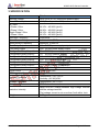
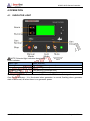
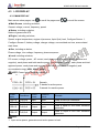
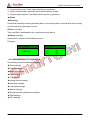
HGM7110VS Genset Controller USER MANUAL ZHENGZHOU SMARTGEN TECHNOLOGY CO.,LTD Chinese trademark English trademark Smartgen — make your generator smart Smartgen Technology Co., Ltd. No. 28 Jinsuo Road Zhengzhou City Henan Province P. R. China Tel: +86-371-67988888 +86-371-67981888 +86-371-67991553 +86-371-67992951 +86-371-67981000(overseas) Fax: 0086-371-67992952 Web: http://www.smartgen.com.cn/ http://www.smartgen.cn/ Email: [email protected] All rights reserved. No part of this publication may be reproduced in any material form (including photocopying or storing in any medium by electronic means or other) without the written permission of the copyright holder. Smartgen Technology reserves the right to change the contents of this document without prior notice. If colors of actual products are different from those mentioned within this manual, please take the actual product as the standard. Version history Date 2014-08-18 Version 1.0 Contents Original release This manual is suitable for HGM7110VS controller only. Clarification of notation used within this publication. SIGN INSTRUCTION Note Highlights an essential element of a procedure to ensure correctness. Caution! Indicates a procedure or practice, which, if not strictly observed, could result in damage or destruction of equipment. Warning! Indicates error operation may cause death, serious injury and significant property damage. HGM7110VS Genset Controller Contents 1 OVERVIEW ......................................................................................................................... 6 2 PERFORMANCE AND CHARACTERISTICS...................................................................... 7 3 SPECIFICATION ................................................................................................................. 9 4 OPERATION...................................................................................................................... 10 4.1 INDICATOR LIGHT ...................................................................................................... 10 4.2 PUSHBUTTONS ........................................................................................................... 11 4.3 LCD DISPLAY .............................................................................................................. 12 4.3.1 MAIN DISPLAY ............................................................................................... 12 4.3.2 PARAMETERS SETTING MENU.................................................................... 13 4.4 AUTO START/STOP OPERATION ........................................................................ 16 4.5 MANUAL START/STOP OPERATION ................................................................... 18 4.6 SWITCH CONTROL PROCEDURES .................................................................... 19 5 PROTECTIONS .......................................................................................................... 20 5.1 WARNING ALARMS .............................................................................................. 20 5.2 SHUTDOWN ALARM ............................................................................................ 22 5.3 TRIP AND STOP ALARM ...................................................................................... 24 5.4 TRIP ALARM ......................................................................................................... 25 6 WIRING CONNECTION .................................................................................................... 26 7 SCOPES AND DEFINITIONS OF PROGRAMMABLE PARAMETERS ............................. 29 7.1. CONTENTS AND SCOPES OF PARAMETERS .................................................. 29 7.2. PROGRAMMABLE OUTPUT PORTS .................................................................. 37 7.2.1 DEFINED PERIOD OUTPUT .......................................................................... 40 7.2.2 DEFINED COMBINATION OUTPUT ............................................................... 41 7.3 PROGRAMMABLE INPUT PORTS (ALL ACTIVE WHEN CONNECT TO GRAND (B-)) ....................................................................................................................................... 42 7.4. SELECTION OF SENSORS ................................................................................... 44 7.5 CONDITIONS OF CRANK DINSCONNECT SELECTION .................................... 45 8 PARAMETERS SETTING.................................................................................................. 46 9 SENSORS SETTING ........................................................................................................ 47 10 COMMISSIONING........................................................................................................... 48 11 TYPICAL APPLICATION .................................................................................................. 49 13.1 GSM SHORT MESSAGE ALARM .......................................................................... 52 13.2 GSM SHORT MESSAGE REMOTE CONTROL .................................................... 52 HGM7110VS Genset Controller Version: 1.0 2014-08-18 Page 4 of 54 HGM7110VS Genset Controller 14 FAULT FINDING .............................................................................................................. 54 HGM7110VS Genset Controller Version: 1.0 2014-08-18 Page 5 of 54 HGM7110VS Genset Controller 1 OVERVIEW HGM7110VS genset controller is used for genset automation and monitor control system of single unit to achieve automatic start/stop, data measure, alarm protection and “three remote” (remote control, remote measuring and remote communication). Controller adjusts engine speed according to genset present power so as to realize energy saving and pollution reduction. The controller adopts large liquid crystal display (LCD) and selectable Chinese, English or other languages interface with easy and reliable operation. HGM7110VS controller adopts 32 bits micro-processor technology with precision parameters measuring, fixed value adjustment, time setting and threshold adjusting and etc. The majority of parameters can be set using front panel and all the parameters can be set using PC (via USB port) and can be adjusted and monitored with the help of RS485 ports. It can be widely used in all types of automatic genset control system with compact structure, advanced circuits, simple connections and high reliability. HGM7110VS Genset Controller Version: 1.0 2014-08-18 Page 6 of 54 HGM7110VS Genset Controller 2 PERFORMANCE AND CHARACTERISTICS With ARM-based 32-bit SCM, highly integrated hardware, new reliability level; 132x64 LCD with backlight, multilingual interface (including English, Chinese or other languages) which can be chosen at the site, making commissioning convenient for factory personnel; Improved LCD wear-resistance and scratch resistance due to hard screen acrylic; Silicon rubber panel and pushbuttons for better operation in high/low temperature environment; GOV output port enables controller adjusts engine speed according to genset present power so as to realize energy saving and pollution reduction. RS485 communication port enables remote control, remote measuring, remote communication via ModBus protocol. Equipped with SMS (Short Message Service) function. When genset is alarming, controller can send short messages via SMS automatically to max. 5 telephone numbers. Besides, generator status can be controlled and checked using SMS; Suitable for 3 phase 4 wire, 3 phase 3 wire, single phase 2 wire, 2 phase 3 wire (120/240V) power supply, 50/60Hz system. Collects and shows 3-phase voltage, current, power parameter and frequency of generator. Generator Line voltage (Uab, Ubc, and Uca) Phase voltage (Ua, Ub, and Uc) Phase sequence Frequency Hz Load DC voltage, AC Current Current, IA, Power IB, IC Each phase and total active power kW Each phase and total reactive power Each phase and total apparent power kVar kVA Each phase and average power factor PF Accumulate total generator power kWh, kVarh, kVAh Collect and display DC voltage, current and power. For generator, controller has over and under voltage, over and under frequency, loss of phase, phase sequence wrong, over and reverse power, over current functions; 3 fixed analog sensors (temperature, oil pressure and liquid level); 2 configurable sensors can be set as sensor of temperature, oil pressure or fuel level; HGM7110VS Genset Controller Version: 1.0 2014-08-18 Page 7 of 54 HGM7110VS Genset Controller Precision measure and display parameters about Engine, Temp. (WT) °C/°F both be displayed Oil pressure (OP) kPa/Psi/Bar all be displayed Fuel level (FL) %(unit) Speed (SPD) r/min (unit) Voltage of Battery (VB) Voltage of Charger (VD) V (unit) V (unit) Hour count (HC) can accumulate to max. 65535 hours. Start times can accumulate to max. 65535 times. Protection: automatic start/stop of the genset, ATS(Auto Transfer Switch) control with perfect fault indication and protection function; All output ports are relay-out; Parameter setting: parameters can be modified and stored in internal EEPROM memory and cannot be lost even in case of power outage; most of them can be adjusted using front panel of the controller and all of them can be modified using PC via USB or RS485 ports. More kinds of curves of temperature, oil pressure, fuel level can be used directly and users can define the sensor curves by themselves; Multiple crank disconnect conditions (speed sensor, oil pressure, generator frequency) are optional; Widely power supply range DC(8~35)V, suitable to different starting battery voltage environment; Event log and real-time clock function; Scheduled start & stop generator (can be set as start genset once a day/week/month whether with load or not); Selectable configuration: Users can choose different configuration via input port. Can be used on pumping units and as an indicating instrument (indicate and alarm are enable only, relay is inhibited ); With maintenance function. Actions (warning, trip and stop) can be set when maintenance time out; All parameters used digital adjustment, instead of conventional analog modulation with normal potentiometer, more reliability and stability; Waterproof security level IP55 due to rubber seal installed between the controller enclosure and panel fascia; Metal fixing clips enable perfect in high temperature environment; Modular design, self-extinguishing ABS plastic enclosure, pluggable connection terminals and embedded installation way; compact structure with easy mounting. HGM7110VS Genset Controller Version: 1.0 2014-08-18 Page 8 of 54 HGM7110VS Genset Controller 3 SPECIFICATION Parameter Working Voltage Overall Consumption AC Input: 3 Phase 4 Wire 3 Phase 3 Wire Single Phase 2 Wire 2 Phase 3 Wire Alternator Frequency Speed Sensor Voltage Speed Sensor Frequency Start Relay Output Fuel Relay Output Configurable Relay Output 1 Configurable Relay Output 2 Configurable Relay Output 3 Configurable Relay Output 4 Configurable Relay Output 5 Configurable Relay Output 6 Case Dimensions Panel Cutout CT Secondary Current Working Conditions Storage Conditions Protection Level Insulation Intensity Weight HGM7110VS Genset Controller Details DC8. 0V to 35. 0V, continuous power supply <3W (Standby mode: ≤2W) AC15V ~ AC360V (ph-N) AC30V ~ AC620V (ph-ph) AC15V ~ AC360V (ph-N) AC15V ~ AC360V (ph-N) 50Hz/60Hz 1. 0 V to 24 V (RMS) Maximum 10,000 Hz 16A DC28V power supply output 16A DC28V power supply output 7A DC28V power supply output 7A AC250V passive output 16A AC250V passive output 16A AC250V passive output 7A DC28V power supply output 7A DC28V power supply output 197mm x 152mm x 47mm 186mm x 141mm Rated 5A Temperature: (-25~+70)°C Humidity: (20~93)%RH Temperature:(-25~+70)°C IP55 Gasket Apply AC2.2kV voltage between high voltage terminal and low voltage terminal; The leakage current is not more than 3mA within 1min. 0.75kg Version: 1.0 2014-08-18 Page 9 of 54 HGM7110VS Genset Controller 4 OPERATION 4.1 INDICATOR LIGHT NOTE: Selected light indicators description: Alarm indicator: Alarm Type Alarm Indicator Warning Slow flashing (1time per sec) Trip Alarm Slow flashing (1 time per sec) Shutdown Alarm Fast flashing (5 times per sec) Trip and Stop Alarm Fast flashing (5 times per sec) Running indicator: illuminated from crank disconnect to ETS while off during other periods. Gen normal indicator:It is illuminated when generator is normal; flashing when generator state is abnormal; off when there is no generator power. HGM7110VS Genset Controller Version: 1.0 2014-08-18 Page 10 of 54 HGM7110VS Genset Controller 4.2 PUSHBUTTONS Stop Stop running generator in Auto/Manual mode; Lamp test (press at least 3 seconds); Reset alarm in stop mode; During stopping process, press this button again to stop generator immediately. Start Start genset in Manual/Test mode. Manual Mode Press this key and controller enters in Manual mode. Auto Mode Press this key and controller enters in Auto mode. Mute/Reset Alarm Gen Close/Open Alarming sound off; If there is trip alarm, pressing the button at least 3 seconds can reset this alarm. Can control generator to switch on or off in Manual mode. 1) Page turning; 2) Press it at least 3 seconds to enters in basic Page parameter setting menu and shift cursor to confirm the set Scroll/Confirm information. 1) Screen scroll; Up/Increase 2) Up cursor and increase value in setting menu. Down/Decrea 1) Screen scroll; 2) Down cursor and decrease value in setting menu. se NOTE: Pressing and holding for more than 3 seconds can enter into parameters setting menu. NOTE: and Pressing and simultaneously will increase LCD contrast; Pressing simultaneously will decrease LCD contrast; When controller is powered on after outage, LCD contrast will return factory default. WARNING: Default password is 00318, user can change it in case of others change the advanced parameters setting. Please clearly remember the password after changing. If you forget it, please contact Smartgen services and send all information in the controller page of “ABOUT” to us. HGM7110VS Genset Controller Version: 1.0 2014-08-18 Page 11 of 54 HGM7110VS Genset Controller 4.3 LCD DISPLAY 4.3.1 MAIN DISPLAY Main screen show pages; use to scroll the pages and to scroll the screen. ★Main Screen, including as below, Genset: voltage, current, frequency, speed ★Status, including as below, Status of genset and ATS ★Engine, including as below, Speed, engine temperature, engine oil pressure, liquid (fuel) level, Configure Sensor 1, Configure Sensor 2, battery voltage, charger voltage, accumulated run time, accumulated start times. ★Gen, including as below, Phase voltage, Line voltage, frequency, phase sequence ★Load, including as below, DC current, voltage, power , AC current, each phase and total active power (positive and negative), each phase and total reactive power (positive and negative), each phase and total apparent power, each phase and average power factor (positive and negative) and accumulated energy (kWh, kVarh, kVAh). NOTE: Power factor shows as following, Remark: P stands for active power Q stands for reactive power Power factor COS>0L COS>0C P>0,Q>0 P>0,Q<0 Active power Input Input Reactive power Input Output COS<0L P<0,Q>0 Output Input COS<0C P<0,Q<0 Output Output Conditions Remark Load is inductive resistance. Load is capacitance resistance. Load is equal to one under excitation generator. Load is equal to one over excitation generator. Note: 1. Input active power, generator send active power to load. HGM7110VS Genset Controller Version: 1.0 2014-08-18 Page 12 of 54 HGM7110VS Genset Controller 2. Output active power, load supply electricity to generator. 3. Input reactive power, generator send reactive power to load. 4. Output reactive power, load send reactive power to generator. ★Alarm: ★Event log Records all start/stop events (shutdown alarm, trip and stop alarm, manual /auto start or stop) and the real time when alarm occurs. Others, including, Time and Date, maintenance due, input/output ports status. ★About, including, Issue time of software and hardware version Example: Gen Volts L1-N L2-N L3-N Engine Speed 1500r/min 0V 0V 0V 4.3.2 PARAMETERS SETTING MENU Parameters setting including as following, ★Timer settings ★Engine settings ★Generator settings ★Load settings ★ATS settings ★Analog sensor settings ★Input port settings ★output port settings ★Module settings ★Scheduling and maintenance settings ★GSM settings ★GOV settings HGM7110VS Genset Controller Version: 1.0 2014-08-18 Page 13 of 54 HGM7110VS Genset Controller Example: Advanced Parameters >Timer >Engine >Generator >Load Generator >Return >AC System >Poles >Rated Voltage Form1: Use to scroll settings, to enter settings (form 2), to exit settings menu. Form 2: to scroll settings (form 3); select “return” and Use press to return to previous menu (form 1), or press to return to previous menu (form 1). Generator > Under Volt Shutdown > Over Freq Shutdown > Under Freq Shutdown > Over Volt Warn Form 3: Gen Over Volt Warn Sel:Disable Set Value:00110% Return Value: 00108% Delay: 00005 Form 4: Use to scroll settings, to enter settings (form 4), to return to previous menu. (form 1) Use to enter settings (form 5), previous menu (form 3), to return to to return to previous menu. (form 3) Gen Over Volt Warn Sel:Disable Set Value: 00110% Return Value: 00108% Delay: 00005 Form 5: Gen Over Volt Warn Sel:Enable Set Value: 00110% Return Value: 00108% Delay: 00005 Form 6: Gen Over Volt Warn Sel:Enable Set Value: 00110% Return Value: 00108% Delay: 00005 Form 7: HGM7110VS Genset Controller Use to scroll settings(form 6), (form 7), Use Use to exit settings menu. (form 4) to scroll settings(form 5), (form 7), to enter settings to enter settings to exit settings menu. (form 4) to scroll settings(form 5), to enter settings, to exit settings menu. (form 4) Version: 1.0 2014-08-18 Page 14 of 54 HGM7110VS Genset Controller Gen Over Volt Warn Sel:Disable Set Value: 00110% Return Value: 00108% Delay: 00005 Form 8: Use NOTE: Long time pressing HGM7110VS Genset Controller to scroll settings, to enter settings (form 4), to exit settings menu. (form 4) can exit setting directly during setting. Version: 1.0 2014-08-18 Page 15 of 54 HGM7110VS Genset Controller 4.4 AUTO START/STOP OPERATION Auto mode is selected by pressing the button; a LED besides the button will illuminate to confirm the operation. Starting Sequence: 1. When “Remote Start (with load)” is active, “Start Delay” timer is initiated. 2. “Start Delay” countdown will be displayed on LCD display; 3. When start delay is over, preheat relay energizes (if configured), “preheat delay XXs” information will be displayed on LCD display; 4. After the above delay, the Fuel Relay (if configured) is energized, and then one second later, the Start Relay is engaged. The engine is cranked for a pre-set time. If the engine fails to fire during this cranking attempt then the fuel relay and start relay are disengaged for the pre-set rest period; “crank rest time” begins and wait for the next crank attempt. 5. Should this start sequence continue beyond the set number of attempts, the start sequence will be terminated, and Fail to Start fault will be displayed on LCD display. 6. In case of successful crank attempt, the “Safety On” timer is activated, allowing Low Oil Pressure, High Temperature, Under speed and Charge Alternator Failure inputs to stabilise without triggering the fault. As soon as this delay is over, “start idle” delay is initiated (if configured). 7. During “start idle” delay, under speed, under frequency, under voltage alarms are inhibited. When this delay is over, “warming up” delay is initiated (if configured). 8. After the “warming up” delay, if generator status is normal, its indicator will be illuminated. If generator voltage and frequency have reached on-load requirements, then the generator close relay will be energized; genset will take load; generator power indicator will illuminate and generator will enter into Normal Running status. If voltage or frequency is abnormal, the controller will initiate shutdown alarm (alarm information will be displayed on LCD display). Note: When started via “Remote Start (off Load)” input, same procedures as above but generator close relay deactivated, moreover, genset off load in procedure 8. Automatic Stop Sequence, 1) When the “Remote Start” signal is removed, the Stop Delay is initiated. 2) Once this “stop delay” has expired, the Generator Breaker will open and the “Cooling Delay” is then initiated. Generator power indicator will extinguish. 3) During “Stop Idle” Delay (if configured), idle relay is energized. HGM7110VS Genset Controller Version: 1.0 2014-08-18 Page 16 of 54 HGM7110VS Genset Controller 4) “ETS Solenoid Hold” begins, ETS relay is energized while fuel relay is de-energized, complete stop is detected automatically. 5) "Fail to Stop Delay" begins, complete stop is detected automatically. 6) When generator is stop completely, “After stop” delay will be initiated. Otherwise, fail to stop alarm is initiated and the corresponding alarm information is displayed on LCD display. (If generator is stop successfully after “fail to stop” alarm has initiated, “After stop” delay will be initiated and the alarm will be removed). 7) Generator is placed into its standby mode after its “After stop” delay. HGM7110VS Genset Controller Version: 1.0 2014-08-18 Page 17 of 54 HGM7110VS Genset Controller 4.5 MANUAL START/STOP OPERATION 1 Manual mode is selected by pressing the button; a LED besides the button will illuminate to confirm the operation; Then press button to start the generator, it can automatically judge crank success and accelerate to high speed running. If high temperature, low oil pressure, over speed and abnormal voltage occur during genset running, controller can effectively protect genset to stop (detail procedures please refer to No.3~8 of Auto Start Sequence). In “manual mode ”, the procedures of ATS please refer to Switch Control Procedure of generator in this manual. 2 Manual stop: pressing key can shut down the running genset. (detail procedures please refer to No.2~7 of Auto Stop Sequence) HGM7110VS Genset Controller Version: 1.0 2014-08-18 Page 18 of 54 HGM7110VS Genset Controller 4.6 SWITCH CONTROL PROCEDURES MANUAL TRANSFER PROCEDURES: When controller is in Manual mode, the switch control procedures will start through manual transfer procedures. Users can control the loading transfer of ATS via pressing Press generator switch on key button to switch on or off. , if generator have taken load, will output unload signal; if taken no load, generator will output load signal. AUTO TRANSFER PROCEDURES: When controller is in AUTO/TEST/STOP mode, auto control will be executive. 1. If input port is configured as Close Generator Auxiliary ◆ If “Open breaker detect” is “SELECT Enable” Generator load is transferred into generator un-load, after the open delay; switch off signal will be output while “fail to transfer” delay will be initiated. Once the delay has expired, if switch off failed, it will wait for switch off. Otherwise, switch off is completed. Generator unload is transferred into generator load, after the close delay, switch on signal will be output while “fail to transfer” delay will be initiated. Once the delay has expired, if switch on failed, it will wait for switch on. Otherwise, switch on is completed. If “fail to transfer” warn is “Enable”, alarm signal will be initiated whatever switch on or off failure. ◆ If “Open breaker detect” is “SELECT Disable” Generator load is transferred into generator unload, after the open delay, switch off is completed. Generator unload is transferred into generator load, after the close delay, switch on signal will be output while “fail to transfer” delay will be initiated. Once the delay has expired, if switch on failed, it will wait for switch on. Otherwise, switch on is completed. If “fail to transfer” warn is “Enable”, alarm signal will be initiated f switch on failure. 2. If input port is NOT configured as Close Generator Auxiliary Generator un-load is transferred into generator load, close generator output. Generator load is transferred into generator un-load, open generator output. HGM7110VS Genset Controller Version: 1.0 2014-08-18 Page 19 of 54 HGM7110VS Genset Controller 5 PROTECTIONS 5.1 WARNING ALARMS Warnings are not shutdown alarms and do not affect the operation of the gen-set. Warning alarms does not lead to shutdown. Warning alarms types are as follows: No. Type Description When the controller detects that the engine speed has 1 Over Speed exceeded the pre-set value, it will initiate a warning alarm. When the controller detects that the engine speed has fallen 2 Under Speed below the pre-set value, it will initiate a warning alarm. Loss of Speed When the controller detects that the engine speed is 0 and the 3 Signal action select “Warn”, it will initiate a warning alarm. When the controller detects that the genset frequency has 4 Gen Over Frequency exceeded the pre-set value, it will initiate a warning alarm. Gen Under When the controller detects that the genset frequency has 5 Frequency fallen below the pre-set value, it will initiate a warning alarm. When the controller detects that the generator voltage has 6 Gen Over Voltage exceeded the pre-set value, the controller will initiate a warning alarm. Genset Under When the controller detects that the genset voltage has fallen 7 Voltage below the pre-set value, it will initiate a warning alarm. When the controller detects that the genset current has 8 Gen Over Current exceeded the pre-set value and the action select “Warn”, it will initiate a warning alarm. After “fail to stop” delay, if gen-set does not stop completely, it 9 Fail To Stop will initiate a warning alarm. Charge Alternator When the controller detects that charger voltage has fallen 10 Failure below the pre-set value, it will initiate a warning alarm. When the controller detects that start battery voltage has 11 Battery Over Volt exceeded the pre-set value, it will initiate a warning alarm. When the controller detects that start battery voltage has 12 Battery Under Volt fallen below the pre-set value, it will initiate a warning alarm. When count down time is 0 and the action select “Warn”, it will 13 Maintenance Due initiate a warning alarm. If reverse power detection is enabled, when the controller detects that the reverse power value (power is negative) has 14 Reverse Power fallen below the pre-set value and the action select “Warn”, it will initiate a warning alarm. If over power detection is enabled, when the controller detects that the over power value (power is positive) has exceeded 15 Over Power the pre-set value and the action select “Warn”, it will initiate a warning alarm. If loss of phase detection is enabled, When controller detects 16 Gen Loss of Phase the generator loss phase, it will initiate a warning alarm. Gen Phase When the controller detects a phase rotation error, it will 17 Sequence Wrong initiate a warning alarm. When the controller detects that the breaker close or open 18 Switch Fail Warn failure occurs, and the action select “Warn”, it will initiate a HGM7110VS Genset Controller Version: 1.0 2014-08-18 Page 20 of 54 HGM7110VS Genset Controller No. Type 19 Temperature Sensor Open Circuit 20 High Temperature 21 Low Temperature 22 Oil Pressure Open Circuit 23 Low Oil Pressure 24 Level Sensor Open Circuit 25 Low Fuel Level 26 Flexible Sensor Open Circuit 1 Flexible High Flexible Low Sensor 1 Sensor 1 Flexible Sensor Open Circuit 2 Flexible High Flexible Low Sensor 2 Sensor 2 27 28 29 30 31 32 Digital Input 33 GSM COM Failure HGM7110VS Genset Controller Description warning alarm. When the controller detects that the temperature sensor is open circuit and the action select “Warn”, it will initiate a warning alarm. When the controller detects that engine temperature has exceeded the pre-set value, it will initiate a warning alarm. When the controller detects that engine temperature has fallen below the pre-set value, it will initiate a warning alarm. When the controller detects that the oil pressure sensor is open circuit and the action select “Warn”, it will initiate a warning alarm. When the controller detects that the oil pressure has fallen below the pre-set value, it will initiate a warning alarm. When the controller detects that the level sensor is open circuit and the action select “Warn”, it will initiate a warning alarm. When the controller detects that the fuel level has fallen below the pre-set value, it will initiate a warning alarm. When the controller detects that the flexible sensor 1 is open circuit and the action select “Warn”, it will initiate a warning alarm. When the controller detects that the sensor 1 value has exceeded the pre-set value, it will initiate a warning alarm. When the controller detects that the sensor 1 value has fallen below the pre-set value, it will initiate a warning alarm. When the controller detects that the flexible sensor 2 is open circuit and the action select “Warn”, it will initiate a warning alarm. When the controller detects that the sensor 2 value has exceeded the pre-set value, it will initiate a warning alarm. When the controller detects that the sensor 2 value has fallen below the pre-set value, it will initiate a warning alarm. When digit input port is set as warning and the alarm is active, it will initiate a warning alarm. When GSM is enable but the controller couldn‟t detect GSM module, it will initiate a warning alarm. Version: 1.0 2014-08-18 Page 21 of 54 HGM7110VS Genset Controller 5.2 SHUTDOWN ALARM When controller detects shutdown alarm, it will send signal to open breaker and shuts down generator. Shutdown alarms as following: No. Type Description When the controller detects an emergency stop alarm signal, 1 Emergency Stop it will initiate a shutdown alarm. When the controller detects that the generator speed has 2 Over Speed exceeded the pre-set value, it will initiate a shutdown alarm. When the controller detects that the generator speed has 3 Under Speed fallen below the pre-set value, it will initiate a shutdown alarm. When the controller detects that the engine speed is 0 and the 4 Loss of Speed Signal action select “Shutdown”, it will initiate a shutdown alarm. When the controller detects that the genset frequency has 5 Gen Over Frequency exceeded the pre-set value, it will initiate a shutdown alarm. Gen Under When the controller detects that the genset frequency has 6 Frequency fallen below the pre-set value, it will initiate a shutdown alarm. When the controller detects that the generator voltage has 7 Gen Over Voltage exceeded the pre-set value, the controller will initiate a shutdown alarm. When the controller detects that the genset voltage has fallen 8 Gen Under Voltage below the pre-set value, it will initiate a shutdown alarm. If the engine does not fire after the pre-set number of 9 Fail To Start attempts, it will initiate a shutdown alarm. When the controller detects that the genset current has 10 Gen Over Current exceeded the pre-set value and the action select “Shutdown”, it will initiate a shutdown alarm. When count down time is 0 and the action select “Shutdown”, 11 Maintenance Due it will initiate a shutdown alarm. If reverse power detection is enabled, when the controller detects that the reverse power value (power is negative) has 12 Reverse Power fallen below the pre-set value and the action select “Shutdown”, it will initiate a shutdown alarm. If over power detection is enabled, when the controller detects that the over power value (power is positive) has exceeded 13 Over Power the pre-set value and the action select “Shutdown”, it will initiate a shutdown alarm. When the controller detects that the temperature sensor is Temperature Sensor 14 open circuit and the action select “Shutdown”, it will initiate a Open Circuit shutdown alarm. When the controller detects that engine temperature has 15 High Temperature exceeded the pre-set value, it will initiate a shutdown alarm. When the controller detects that the oil pressure sensor is Oil Pressure Open 16 open circuit and the action select “Shutdown”, it will initiate a Circuit shutdown alarm. When the controller detects that the oil pressure has fallen 17 Low Oil Pressure below the pre-set value, it will initiate a shutdown alarm. HGM7110VS Genset Controller Version: 1.0 2014-08-18 Page 22 of 54 HGM7110VS Genset Controller No. Type 18 Level Sensor Open Circuit 19 Flexible Sensor Open Circuit 1 Flexible High Flexible Low Sensor 1 Sensor 1 Flexible Sensor Open Circuit 2 Flexible High Flexible Low Sensor 2 Sensor 2 20 21 22 23 24 25 Digital Input HGM7110VS Genset Controller Description When the controller detects that the level sensor is open circuit and the action select “Shutdown”, it will initiate a shutdown alarm. When the controller detects that the flexible sensor 1 is open circuit and the action select “Shutdown”, it will initiate a shutdown alarm. When the controller detects that the sensor 1 value has exceeded the pre-set value, it will initiate a shutdown alarm. When the controller detects that the sensor 1 value has fallen below the pre-set value, it will initiate a shutdown alarm. When the controller detects that the flexible sensor 2 is open circuit and the action select “Shutdown”, it will initiate a shutdown alarm. When the controller detects that the sensor 2 value has exceeded the pre-set value, it will initiate a shutdown alarm. When the controller detects that the sensor 2 value has fallen below the pre-set value, it will initiate a shutdown alarm. When digit input port is set as shutdown and the alarm is active, it will initiate a shutdown alarm. Version: 1.0 2014-08-18 Page 23 of 54 HGM7110VS Genset Controller 5.3 TRIP AND STOP ALARM On initiation of the trip and stop condition the controller will de-energize the „Close Generator‟ Output to remove the load from the generator. Once this has occurred the controller will start the Cooling delay and allow the engine to cool before shutting down the engine. No. Type Description When the controller detects that the genset current has 1 Gen Over Current exceeded the pre-set value and the action select “Trip and Stop”, it will initiate a trip and stop alarm. When count down time is 0 and the action select “Trip and 2 Maintenance Due Stop”, it will initiate a trip and stop alarm. If reverse power detection is enabled, when the controller detects that the reverse power value (power is negative) has 3 Reverse Power fallen below the pre-set value and the action select “Trip and Stop”, it will initiate a trip and stop alarm. If over power detection is enabled, when the controller detects that the over power value (power is positive) has exceeded 4 Over Power the pre-set value and the action select “Trip and Stop”, it will initiate a trip and stop alarm. When digit input port is set as “Trip and Stop” and the alarm is 5 Digital Input active, it will initiate a trip and stop alarm. HGM7110VS Genset Controller Version: 1.0 2014-08-18 Page 24 of 54 HGM7110VS Genset Controller 5.4 TRIP ALARM On initiation of the trip condition the controller will de-energize the „Close Generator‟ Output without stop the generator. Trip alarm as following, No. Type 1 Gen Over Current 2 Reverse Power 3 Over Power 4 Digital Input HGM7110VS Genset Controller Description When the controller detects that the genset current has exceeded the pre-set value and the action select “Trip”, it will initiate a trip alarm. If reverse power detection is enabled, when the controller detects that the reverse power value (power is negative) has fallen below the pre-set value and the action select “Trip”, it will initiate a trip alarm. If over power detection is enabled, when the controller detects that the over power value (power is positive) has exceeded the pre-set value and the action select “Trip”, it will initiate a trip alarm. When digit input port is set as “Trip” and the alarm is active, it will initiate a trip alarm. Version: 1.0 2014-08-18 Page 25 of 54 HGM7110VS Genset Controller 6 WIRING CONNECTION HGM7110VS controller‟s rear as following: Description of terminal connection: NO. Functions 1 DC Input -Ve Aux. Output 4 Cable Size Remark 2 2.5mm Connected with negative of starter battery. Connected with positive of starter battery. If wire 2 2.5mm length is over 30m, better to double wires in parallel. Max. 20A fuse is recommended. 2 2.5mm Connected with +Ve via emergency stop button. 2 1.5mm +Ve is supplied by terminal 3, rated 16A +Ve is supplied by terminal 3, Connected to 1.5mm2 rated 16A starter coil +Ve is supplied by terminal 2, 1.5mm2 rated 7A Normally close outputs, rated 7A 2 1.5mm Public points of relay Details see Normally open outputs, rated 7A form 2 2 2.5mm Normally open outputs; volts free; rated 16A 2.5mm2 Charger (D+) 1.0mm2 2 DC Input +Ve 3 4 Emergency Stop Fuel (16A) 5 Crank (16A) 6 Aux. Output 1 7 8 9 10 11 12 13 14 Aux. Output 2 Aux. Output 3 HGM7110VS Genset Controller Connected with charger‟s D+ (WL) terminals. Be hanging in the air If there is no this terminal. Version: 1.0 2014-08-18 Page 26 of 54 HGM7110VS Genset Controller NO. Functions 15 Aux. Output 5 16 Aux. Output 6 Gens AC 17 Voltage-U Gens AC 18 Voltage-V Gens AC 19 Voltage-W Gens AC 20 Voltage-N 21 VIN+ 22 VIN23 DC Current (+) 24 DC Current (-) 25 GOV B(+) 26 GOV A(-) 27 MP1 MP2, (-Ve) has already 28 connected internal 29 Engine Temp. 30 Oil Pressure 31 Fuel Level 32 Config. Sensor 1 Cable Size Remark 2 1.5mm +Ve is supplied by terminal 2, rated 7A 2 Details see form 2 1.5mm Connected to A-phase of genset (2A fuse is 1.0mm2 recommended). Connected to B-phase of genset (2A fuse is 1.0mm2 recommended). Connected to C-phase of genset (2A fuse is 1.0mm2 recommended). 33 Config. Sensor 2 1.0mm2 34 +5V OUTPUT 1.0mm2 35 Sensor COM 1.0mm2 36 37 38 39 40 Aux. Input 1 Aux. Input 2 Aux. Input 3 Aux. Input 4 Aux. Input 5 1.0mm2 1.0mm2 1.0mm2 1.0mm2 1.0mm2 41 Aux. Input COM 1.0mm2 42 43 RS485 COM(GND) RS485- 1.0mm2 1.0mm2 1.0mm2 1.0mm2 1.0mm2 0.5mm2 0.5mm2 1.0mm2 1.0mm 2 1.0mm2 1.0mm2 1.0mm2 1.0mm2 / 0.5mm2 HGM7110VS Genset Controller Connected to N-wire of gen-set. Connected to DC voltage sampling Connected to DC current sensor Shielding line is recommended. Shielding layer connect to earth at GOV end. Connected with Speed sensor, shielding line is recommended. Connect to temperature Sensor. Connect to oil pressure sensor. Details see form Connect to fuel level sensor. Connect to temperature sensor, 4 oil pressure sensor or fuel level sensor. Power supply for sensor(current<50mA) A common terminal of sensor, (-Ve) has already connected internal. Ground connected is active (-Ve) Ground connected is active (-Ve) Details see form Ground connected is active (-Ve) 3 Ground connected is active (-Ve) Ground connected is active (-Ve) A common terminal of input port, (-Ve) has already connected internal. Impedance-120Ω shielding wire is recommended, its single-end earthed. Version: 1.0 2014-08-18 Page 27 of 54 HGM7110VS Genset Controller NO. Functions 44 RS485+ Cable Size 0.5mm2 45 CT IA 1.5mm2 46 CT IB 1.5mm2 47 CT IC 1.5mm2 48 CT ICOM RS232 GSM(GND) RS232 RX RS232 TX 1.5mm2 49 50 51 Remark Outside connected to secondary coil of current transformer (rated 5A). Outside connected to secondary coil of current transformer (rated 5A). Outside connected to secondary coil of current transformer (rated 5A). See following installation instruction. 0.5mm2 0.5mm2 0.5mm2 Connected to GSM module. NOTE: USB ports in controller rear panel are configurable parameter ports, user can directly program controller via PC. HGM7110VS Genset Controller Version: 1.0 2014-08-18 Page 28 of 54 HGM7110VS Genset Controller 7 SCOPES AND DEFINITIONS OF PROGRAMMABLE PARAMETERS 7.1. CONTENTS AND SCOPES OF PARAMETERS Form 1 No. Items Parameters Defaults Description Timer Setting 1 Start Delay (0~3600)s 1 2 Stop Delay (0~3600)s 1 3 Preheat Delay (0~3600)s 0 4 Cranking Time (3~60)s 8 5 Crank Rest Time (3~60)s 10 6 Safety On Delay (0-3600)s 10 7 Start Idle Time (0~3600)s 0 8 Warming Up Time (0~3600)s 10 9 Cooling Time (0~3600)s 10 10 Stop Idle Time (0~3600)s 0 11 ETS Hold (0~3600)s 20 12 Fail to Stop Delay (0~3600)s 0 13 After Stop Time (0~3600)s 0 (0~39) 0 Solenoid Time from remote start signal is active to start genset. Time from remote start signal is inactive to stop genset. Time of pre-powering heat plug before starter is powered up. Time of starter power on The waiting time before second power up when engine start fail. Alarms for low oil pressure, high temperature, under speed, under frequency, under voltage, charge fail are inactive. Idle running time of genset when starting. Warming up time between genset switch on and high speed running. Radiating time before genset stop, after it unloads. Idle running time when genset stop. Stop electromagnet‟s power on time when genset is stopping. Time between ending of genset idle delay and stopped when “ETS time” is set as 0; Time between ending of ETS hold delay and stopped when “ETS Hold output time” is not 0. Time between genset stopped and standby. Engine Setting 1 Engine Type HGM7110VS Genset Controller Version: 1.0 Default: Conventional Engine(not 2014-08-18 Page 29 of 54 HGM7110VS Genset Controller No. Items Parameters Defaults 2 Flywheel Teeth (10~300) 118 3 Rated Speed (0~6000)RPM 1500 4 (0~100)% 90 (0~3600)s 5 (0~1) 0 (0~200)% 114 (0~200)% 80 (0~200)% 110 (0~200)% 86 (0~60.0)V 24.0 12 Battery Over Volts (0~200)% 120 13 Battery Volts 85 5 6 7 8 9 10 11 Loading Speed Loss of Speed Signal Loss of Speed Signal Action Over Speed Shutdown Under Speed Shutdown Over Speed Warn Under Speed Warn Battery Rated Voltage Under (0~200)% 14 Charge Alt Fail (0~60.0)V 8.0 15 Start Attempts (1~10) times 3 16 Crank Disconnect (0~6) 2 HGM7110VS Genset Controller Version: 1.0 Description J1939) Tooth number of the engine, for judging of starter separation conditions and inspecting of engine speed. See the installation instructions. Offer standard to over/under/loading speed. judge Setting value is percentage of rated speed. Controller detects when it is ready to load. It won‟t switch on when speed is under loading speed. Time from detecting speed is 0 to confirm the action. 0:Warn; 1:Shutdown Setting value is percentage of rated speed and delay value can be set. Setting value is percentage of rated speed; delay value and return value can be set. Standard for detecting of over/under voltage of battery. Setting value is percentage of rated voltage of battery, delay value and return value can be set. In normal running, when charger D+(WL) voltage under this value, charge failure alarms. Max. Crank times of crank attempts. When reach this number, controller will send start failure signal. See form 5 There are 3 conditions of disconnecting starter with engine. Each condition can be used alone and simultaneously to separating the start motor and genset as soon 2014-08-18 Page 30 of 54 HGM7110VS Genset Controller No. Items Parameters Defaults Description as possible. 17 Disconnect Generator Freq (0~200)% 24 18 Disconnect Engine Speed (0~200)% 24 19 Disconnect Pressure (0~1000)kPa Not Used Oil When generator frequency higher than the set value, starter will be disconnected. See the installation instruction. When generator speed higher than the set value, starter will be disconnected. See the installation instruction. When generator oil pressure higher than the set value, starter will be disconnected. See the installation instruction. Generator Setting 1 AC System (0~3) 0 2 Poles (2-32) 4 3 Rated Voltage (30~30000)V 230 4 Loading Voltage (0~200)% 85 5 Rated Frequency (10.0-600.0)Hz 50.0 6 Loading Frequency (0~200)% 85 7 8 Volt. Trans.(PT) (0~1) Over Volt. (0~200)% Shutdown HGM7110VS Genset Controller 0 120 Version: 1.0 0: 3P4W; 1: 3P3W; 2: 2P3W; 3: 1P2W. Numbers of generator pole, used for calculating starter rotate speed when without speed sensor. To offer standards for detecting of gens‟ over/under voltage and loading voltage. It is primary voltage when using voltage transformer. Setting value is percentage of generator rated voltage. Detect when controller ready to loading. If generator voltage under load voltage, won‟t enter into normally running. To offer standards for detecting of over/under/load frequency. Setting value is percentage of generator rated frequency. Detect when controller ready to loading. When generator frequency under load frequency, it won‟t enter into normal running. 0: Disable; 1:Enable Setting value is percentage of generator rated volt. Delay value 2014-08-18 Page 31 of 54 HGM7110VS Genset Controller No. 9 10 11 Items Under Shutdown Over Shutdown Under Shutdown Volt. Freq. Freq. Parameters Defaults (0~200)% 80 (0~200)% 114 (0~200)% 80 12 Over Volt. Warn (0~200)% 110 13 Under Volt. Warn (0~200)% 84 14 Over Freq. Warn (0~200)% 110 15 Under Freq. Warn (0~200)% 84 16 Loss of Phase 1 (0~1) Phase Sequence (0~1) Wrong Generator Load Setting 1 Current Trans. (5~6000)/5 Full Current 2 (5~6000)A Rating 17 Description can be set. Setting value is percentage of generator rated freq. Delay value can be set. Setting value is percentage of generator rated volt. Delay value and return value can be set. Setting value is percentage of gens rated freq. Delay value and return value can be set. 0: Disable 1: Enable 1 500 500 3 Full kW rating (0~6000)kW 276 4 Over Current (0~200)% 120 5 6 Over Power Reverse Power (0~1) (0~1) 0 0 The ratio of external CT Generator‟s rated current, standard of load current. Generator‟s rated power, standard of load power. Setting value is percentage of generator rated volt. Delay value can be set as definite time or inverse definite minimum time 0: Disable; 1: Enable 0: Disable; 1: Enable Switch Setting 1 Close Time (0~20.0)s 5.0 2 Open Time (0~20.0)s 3.0 3 Check Time (0~20.0)s 5.0 Check Fail (0~1) Enable 5 Open Check (0~1) Module Setting 4 1 Power On Mode (0~2) HGM7110VS Genset Controller 0 Pulse width of generator switch on. When it is 0, means output constantly. Pulse width of generator switch off. Time of detecting switch auxiliary contacts after transferred. 0: Disable 1: Enable. 0 0 Version: 1.0 0: Stop mode 2: Auto mode 1: Manual mode 2014-08-18 Page 32 of 54 HGM7110VS Genset Controller No. Items Parameters Defaults 2 Module Address (1~254) 1 3 Stop Bit (0~1) 0 4 Language (0~2) 0 5 Password (0~65535) 318 (0~1) 0 0: Disable; 1: Enable 0: Disable; 1: Enable Its national and area‟s cods must be added. e.g. China: 8613666666666 0 0: Disable; 1: Enable 0 0: Disable; 1: Enable 0 0: Disable; 1: Enable 7 SGX Details see form 4. 0: Warn; 1: Shutdown; 2: No action Shutdown when sensor temperature higher than this value. Detecting only after safety delay is over. The delay value can be set. Warn when sensor temperature higher than this value. Detecting only after safety delay is over. The delay value and return value can be set. 0: Disable; 1: Enable GSM Setting 1 GSM Enable 2 Phone Number Max.20 digits Scheduling And Maintenance Setting 1 Scheduled Run (0~1) Scheduled Not 2 (0~1) Run 3 Maintenance (0~1) Analog Sensors Setting Temperature Sensor 1 Curve Type (0~15) Open Circuit 2 (0~2) Action 0 3 High Temp. (0~300)ºC Shutdown 98 4 High Temp. Warn (0~300)ºC 95 (0~1) 0 (0~15) 2 (0~2) 0 (0~1000)kPa 103 5 Low Temp. Warn Oil Pressure Sensor 1 Curve Type 2 Open Action 3 Low Shutdown Circuit OP HGM7110VS Genset Controller Version: 1.0 Description Controller‟s address during remote sensing. 0: 2 stop bits; 1: 1 stop bit 0: Simplified Chinese 1: English 2: Others For entering advanced parameters setting. User-defined voltage curve. Details see form 4. 0: Warn 1: Shutdown 2: No action Shutdown when oil pressure lower than this value. Detecting only after safety delay is over. The delay 2014-08-18 Page 33 of 54 HGM7110VS Genset Controller No. 4 Items Low OP Warn Parameters (0~1000)kPa Liquid Level Sensor 1 Curve Type (0~15) Open Circuit 2 (0~2) Action 3 Low Level Warn (0~300)% Defaults 124 4 0 10 Description value can be set. Warn when oil pressure lower than this value. Detecting only after safety delay is over. The delay value and return value can be set. SGH See form 4 0:Warn; 1:Shutdown; 2:No action Warn when level lower than this value. It is detecting all the time. The delay value and return value can be set. Flexible Sensor 1 1 Flexible Sensor 1 (0-1) Setting 0 0: Disable 1: Enable; (can be set as temperature/pressure/liquid lever sensor). 0 0: Disable; 1: Enable; (can be set as temperature/pressure/liquid lever sensor). Flexible Sensor 2 1 Flexible Sensor 2 (0-1) Setting Digital Input Ports Digital Input Port 1 1 Contents Setting (0~50) 28 2 Active Type (0~1) 0 Remote Start On Load Demand. See form 3 0: Closed to active 1: Open to active Digital Input Port 2 1 Contents Setting (0~50) 26 2 Active Type (0~1) 0 High temperature shutdown See form 3 0: Closed to active 1: Open to active Digital Input Port 3 1 Contents Setting (0~50) 27 2 Active Type (0~1) 0 Digital Input Port 4 1 Contents Setting 2 Active Type (0~50) (0~1) 0 0 HGM7110VS Genset Controller Version: 1.0 Low oil pressure shutdown See form 3 0: Closed to active 1: Open to active User defined. See form 3 0: Closed to active 2014-08-18 Page 34 of 54 HGM7110VS Genset Controller No. Items Parameters Defaults 3 Active Range (0~3) 2 4 Active Actions (0~4) 0 5 Active Delay (0~20.0)s 2.0 6 Description (0~50) 0 Digital Input Port 5 1 Contents Setting 2 Active Type (0~1) 0 3 Active Range (0~3) 2 4 Active Actions (0~4) 1 5 Active Delay (0~20.0)s 2.0 6 Description Description 1: Open to active 0: From safety on 1: From starting 2: Always 3:Never 0: Warn; 1: Shutdown; 2:Trip and stop 3:Trip 4: Indication Time from detecting active to confirm LCD display detailed contents when the input is active. User defined. See form 3 0: Closed to active 1: Open to active 0: From safety on 1: From starting 2: Always 3:Never 0: Warn; 1: Shutdown; 2:Trip and stop 3:Trip 4: Indication Time from detecting active to confirm LCD display detailed contents when the input is active Digital Output Ports Digital Output Port 1 1 Contents Setting 2 Active Type Digital Output Port 2 1 Contents Setting 2 Active Type Digital Output Port 3 1 Contents Setting 2 Active Type Digital Output Port 4 1 Contents Setting 2 Active Type Digital Output Port 5 1 Contents Setting 2 Active Type (0~239) 1 (0~1) 0 User defined period output 1 (default output is in preheating) See Form 2 0: Normally open; 1: Normally close (0~239) (0~1) 35 0 Idle control output. See Form 2 0: Normally open; 1: Normally close (0~239) 29 (0~1) 0 Generator closed output. See form 2 0: Normally open; 1: Normally close (0~239) (0~1) 31 0 Reversed. See form 2 0: Normally open; 1: Normally close (0~239) (0~1) 38 0 ETS solenoid hold. See form 2 0: Normally open; 1: Normally close HGM7110VS Genset Controller Version: 1.0 2014-08-18 Page 35 of 54 HGM7110VS Genset Controller No. Items Digital Output Port 6 1 Contents Setting 2 Active Type GOV Setting 1 Output Type Parameters Defaults Description (0~239) (0~1) 48 0 Common alarm. See form 2 0:Normally open; 1:Normally close (0~1) 0 (0~3) 0 0: Continuous;1: Step 0: AC Power; 1: AC Current; 2: DC Power; 3: DC Current GOV output different voltage when different power or current are set. (0~1) 0 2 Load Type 3 Output Curve 4 High Enable 5 GOV (0~10.0)V 3.0 6 7 GOV Delay DC Input Enable (0~3600)s (0~1) 0 0 8 DC Sensor Curve 9 Power Ratio (1~10) 1 Speed HGM7110VS Genset Controller Version: 1.0 0: Disable; 1: Enable GOV output voltage when “GOV High Speed” is enabled. Set “high speed” output delay value. 0: Disable; 1: Enable X means output voltage value while y means the corresponding current value. Active power is multiplier ratio of sample power. 2014-08-18 Page 36 of 54 HGM7110VS Genset Controller 7.2. PROGRAMMABLE OUTPUT PORTS Form 2 No. 0 1 2 3 4 5 6 7 8 9 10 11 12 13~16 Type Not Used Custom Period 1 Custom Period 2 Custom Period 3 Custom Period 4 Custom Period 5 Custom Period 6 Custom Combined 1 Custom Combined 2 Custom Combined 3 Custom Combined 4 Custom Combined 5 Custom Combined 6 Reserved Description Details of function description please see the following. Action when over speed shutdown and emergence stop. It also can close the air inflow to stop the engine as soon as possible. Action when warning, shutdown, trips. Can be connected annunciator externally. When “alarm mute” configurable input port is active, it can remove the alarm. Action when genset start and disconnect when genset stopped completely. 17 Air Flap Control 18 Audible Alarm 19 Louver Control 20 Fuel Pump Control It is controlled by limited threshold of fuel pump. 21 22 23 Heater Control Cooler Control Oil Pre-supply Output 24 Generator Excite 25 26 Pre-Lubricate Remote Control Output 27 GSM Power Supply It is controlled by limited threshold of heater. It is controlled by limited threshold of cooler. Action from “crank on” to “safety on”. Output in start period. If there is no generator frequency during hi-speed running, then output for 2 seconds again. Actions in period of pre-heating to safety run. This port is controlled by communication (PC). Power for GSM module (GSM module is reset when GSM communication failed). 28 29 30 31 32 Reserved Close Gen Output Open Breaker Output Reserved Reserved HGM7110VS Genset Controller Control generator to take load. Control generator to off load. Version: 1.0 2014-08-18 Page 37 of 54 HGM7110VS Genset Controller 33 Start Relay 34 Fuel Relay 35 Idle Control 36 Speed Raise Relay 37 Speed Drop Relay 38 Energize to Stop 39 Speed Drop Pulse 40 41 Reserved Reserved Action when genset start and disconnect when genset stop completely. Used for engine which has idles. Close before starting and open in warming up delay; Close during stopping idle process and open when stop is completed. Action in warming up delay. Action between the period from “stop idle” to “failed to stop”. Used for engines with ETS electromagnet. Close when stop idle is over and open when pre-set “ETS delay” is over. Active 0.1s when controller enters into stop idle, used for control part of ECU dropping to idle speed. 42 Speed Raise Pulse 43 44 Crank Success Generator OK 45 Generator Load Available 46 47 Reserved Reserved 48 Common Alarm 49 Common Trip and Stop 50 51 52 53 Common Shutdown Common Trip Common Warn Reserved 54 Battery Over Voltage 55 Battery Under Voltage 56 Charge Alternator Failure 57~68 69 70 Reserved Digital Input 1 Active Digital Input 2 Active HGM7110VS Genset Controller Active 0.1s when controller enters into warming up delay; used for control part of ECU raising to normal speed. Close when detects a successful start signal. Action when generator is normal. Action in period of generator normal running to high-speed cooling. Action when genset common warning, common shutdown or common trips alarm occurs. Action when common trip and stop alarm occurs. Action when common shutdown alarm occurs. Action when common trips alarm occurs. Action when common warning alarm occurs. Action when battery‟s over voltage warning alarm occurs. Action when battery‟s low voltage warning alarm occurs. Action when charge failure warning alarm occurs. Action when input port 1 is active Action when input port 2 is active Version: 1.0 2014-08-18 Page 38 of 54 HGM7110VS Genset Controller 71 72 73 74~98 99 100 101 102 103 104 105 106~108 Digital Input 3 Active Digital Input 4 Active Digital Input 5 Active Reserved Emergency Stop Fail To Start Fail To Stop Under Speed Warn Under Speed Shutdown Over Speed Warn Over Speed Shutdown Reserved 109 Gen Over Freq. Warn 110 Gen Over Freq. Shut 111 Gen Over Volt Warn 112 Gen Over Volt Shut 113 Gen Under Freq. Warn 114 Gen Under Freq. Shut 115 Gen Under Volt. Warn 116 Gen Under Volt. Shut 117 Gen Loss of Phase Gen Phase Sequence Action when generator reverse phase. Wrong Reserved Action when controller detects generator over Over Power power occurs. Reserved Action when controller detects generator have Generator Reverse Power reverse power. Over Current Action when generator over current occurs. Reserved High Temp Warn Action when hi-temperature warning occurs. Low Temp Warn Action when low temperature warning occurs. Action when high-temperature shutdown alarm High Temp Shutdown occurs. Reserved 118 119 120 121 122 123 124~138 139 140 141 142 HGM7110VS Genset Controller Action when input port 3 is active Action when input port 4 is active Action when input port 5 is active Action when emergency stop alarm. Action when start failure alarm. Action when stop failure alarm. Action when under speed alarm. Action when under speed shutdown alarm. Action when over speed warns. Action when over speed shutdown alarm. Action when generator over frequency warning occurs. Action when generator over frequency shutdown alarm occurs. Action when generator over voltage warning occurs. Action when generator over voltage shutdown occurs. Action when generator low frequency warning occurs. Action when generator low frequency shutdown occurs. Action when generator low voltage warning occurs. Action when generator low voltage shutdown occurs. Action when generator loss phase. Version: 1.0 2014-08-18 Page 39 of 54 HGM7110VS Genset Controller 143 Low OP Warn 144 Low OP Shutdown 145 146 147 148 149 150 151 Oil Pressure Open Circuit Reserved Low Fuel Level Reserved Reserved Config. Sensor 1 High Warn Config. Sensor 1 Low Warn Config. Sensor 1 High Shut Config. Sensor 1 Low Shut Config. Sensor 2 High Warn Config. Sensor 2 Low Warn Config. Sensor 2 High Shut Config. Sensor 2 Low Shut Reserved Stop Mode Manual Mode Reserved Auto Mode Generator Load Reserved 152 153 154 155 156 157 158~229 230 231 232 233 234 235~239 Action when low oil pressure warning occurs. Action when low oil pressure shutdown alarm occurs. Action when oil pressure sensor is open circuit. Action when low fuel level alarm occurs. Action in stop mode. Action in Manual mode. Action in Auto mode. 7.2.1 DEFINED PERIOD OUTPUT Defined Period output is composed by 2 parts, period output S1 and condition output S2. While S1 and S2 are TRUE synchronously, OUTPUT; While S1 or S2 is FALSE, NOT OUTPUT. Period output S1, can set generator‟s one or more period output freely, can set the delayed time and output time after enter into period. Condition output S2, can be set as any item is given in the section entitled Programmable Output Ports elsewhere in this manual. NOTE: when delay time and output time both are 0 in period output S1, means it is TRUE in this period. Example: HGM7110VS Genset Controller Version: 1.0 2014-08-18 Page 40 of 54 HGM7110VS Genset Controller Output period: start Delay time: 2s Output time: 3s Condition output contents: output port 1 is active Close when condition output active/inactive: close when active (disconnect when inactive); Output port 1 active: after enter “starting time” and delay 2s, this defined period output is outputting, after 3s, stop outputting; Output port 1 inactive: defined output period is not outputting. 7.2.2 DEFINED COMBINATION OUTPUT Defined combination output is composed by 3 parts, condition output S1 or S2 and condition output S3. S1 or S2 is TRUE, while S3 is TRUE, Defined combination output is outputting; S1 and S2 are FALSE, or S3 is FALSE, Defined combination output is not outputting. NOTE: S1, S2, S3 can be set as any item except for “defined combination output” which is given in the section entitled Programmable Output Ports elsewhere in this manual. NOTE: 3 parts of defined combination output (S1, S2, S3) couldn‟t include or recursively include themselves. Example, Contents of condition output S1: output port 1 is active; Close when condition output S1 is active /inactive: close when active (disconnect when inactive); Contents of condition output S2: output port 2 is active; Close when condition output S2 is active /inactive: close when active (disconnect when inactive); Contents of condition output S3: output port 3 is active; Close when condition output S3 is active /inactive: close when active (disconnect when inactive); When input port 1 active or input port 2 active, if input port 3 is active, Defined Combination Output is outputting; If input port 3 inactive, Defined Combination Output is not outputting; When input port 1 inactive and moreover, input port 2 inactive, whatever input port 3 is active or not, Defined Combination Output is not outputting. HGM7110VS Genset Controller Version: 1.0 2014-08-18 Page 41 of 54 HGM7110VS Genset Controller 7.3 PROGRAMMABLE INPUT PORTS (ALL ACTIVE WHEN CONNECT TO GRAND (B-)) Form 3 No. Type 0 Users Configured 1 2 Reserved Alarm Mute 3 Reset Alarm 4 5 60Hz Active Lamp Test 6 Panel Lock 7 8 High Speed Mode Idle Control Mode 9 Inhibit Auto Stop 10 Inhibit Auto Start 11 Inhibit Scheduled 12 13 14 15 16 Reserved Aux Gen Closed Inhibit Gen Load Reserved Reserved 17 Auto Mode Lock 18 Auto Mode Invalid HGM7110VS Genset Controller Description Including following functions, Indication: indicate only, not warning or shutdown. Warning: warn only, not shutdown. Shutdown: alarm and shutdown immediately Trip and stop: alarm, generator unloads and shutdown after hi-speed cooling Trip: alarm, generator unloads but not shutdown. Never: input inactive. Always: input is active all the time. From crank: detecting from generator start. From safety on: detecting after safety on delay. Can prohibit “Audible Alarm” output when input is active. Can reset shutdown alarm and trip alarm when input is active. Use for CANBUS engine and it is 60Hz when input is active. All LED indicators are illuminating when input is active. All buttons in panel is inactive except and there is in the right of first row in LCD when input is active. GOV output setting voltage when the input is active. Under voltage/frequency/speed protection is inactive. In Auto mode, during generator normal running, when input is active, prohibit generator shutdown automatically. In Auto mode, prohibit generator start automatically when input is active. In Auto mode, prohibit fixed timing start genset when input is active. Connect generator loading switch‟s auxiliary point. Prohibit genset switch on when input is active. When input is active, controller enters into Auto Mode; all the keys except are inactive and there is in the right of first row in LCD. When input is active, controller won‟t work under Auto Version: 1.0 2014-08-18 Page 42 of 54 HGM7110VS Genset Controller Mode. 19 20 Reserved Reserved 21 Inhibit Alarm Stop key and simulate auto key input does not work. All shutdown alarms are prohibited except emergence stop.(i.e. battle mode or override mode) 25 Aux Instrument All outputs are prohibited in this mode. Mode Reserved Controller will set maintenance time and date as default Reset Maintenance when input is active. Reserved 26 Aux. High Temp 27 Aux. Low OP 28 Remote Start (On Load) 29 Remote Start (Off Load) 30 Aux. Manual Start 31 32 33 39~46 Reserved Reserved Simulate Stop key Simulate Manual key Reserved Simulate Auto key Simulate Start key Simulate Gen Load key Reserved 47 Alternative Config1 48 Alternative Config2 49 Alternative Config3 50 Reserved 22 23 24 34 35 36 37 38 HGM7110VS Genset Controller Connect to sensor digital input. Connect to sensor digital input. In Auto mode, when input is active, can start genset automatically and with load when genset is normal running; when input is inactive, can stop genset automatically. In Auto mode, when input is active, can start genset automatically and off load when genset is normal running; when input is inactive, can stop genset automatically. In Manual mode, when input is active, can start genset automatically; when input is inactive, can stop genset automatically. An external button; can be connected to simulate panel button. An external button; can be connected to simulate panel button. Alternative configuration is active when the input is active. Users can set different parameters to make it easy to select current configuration via input port. Version: 1.0 2014-08-18 Page 43 of 54 HGM7110VS Genset Controller 7.4. SELECTION OF SENSORS Form4 No. 1 2 3 Items Description 0 Not used 1 Custom Res Curve 2 Custom 4-20mA curve 3 VDO 4 CURTIS Temperature 5 VOLVO-EC Sensor 6 DATCON 7 SGX 8 SGD 9 SGH 10 PT100 11~15 Reserved 0 Not used 1 Custom Res Curve 2 Custom Voltage Curve 3 VDO 10Bar 4 CURTIS Pressure 5 VOLVO-EC Sensor 6 DATCON 10Bar 7 SGX 8 SGD 9 SGH 10~15 Reserved 0 Not used 1 Custom Res Curve Fuel Level 2 Custom 4-20mA Curve Sensor 3 SGD 4 SGH 5~15 Reserved Remark Defined resistance‟s range is (0~6)KΩ, default is SGX sensor. Defined resistance‟s range is (0~6)KΩ, default is SGX sensor. Defined resistance‟s range is (0~6)KΩ, default is SGH sensor. NOTE: User should make special declare when order controller if your genset equip with 4~20mA sensor. HGM7110VS Genset Controller Version: 1.0 2014-08-18 Page 44 of 54 HGM7110VS Genset Controller 7.5 CONDITIONS OF CRANK DINSCONNECT SELECTION No. 0 1 2 3 4 5 6 Setting description Generator Frequency Engine Speed Engine Speed + Generator Frequency Oil pressure Oil pressure + Generator Frequency Oil pressure + Engine Speed Oil pressure + Engine Speed + Generator Frequency NOTE: 1) There are 3 conditions to make starter disconnected with engine, that is, engine speed, generator frequency and oil pressure. They all can be used separately. We recommend that oil pressure should be using with speed sensor and generator frequency together, in order to make the starter separate with engine as soon as possible and can check start exactly. 2) Speed sensor is the magnetic equipment which be installed in starter for detecting flywheel teeth. 3) When set as engine speed, must ensure that the number of flywheel teeth is as same as setting, otherwise, “over speed stop” or “under speed stop” may be caused. 4) If genset without speed sensor, please don‟t select corresponding items which include engine speed, otherwise, “start fail” or “loss of speed signal” maybe caused. 5) If genset without oil pressure sensor, please don‟t select corresponding items which include oil pressure. 6) If not select generator frequency in crank disconnect setting, controller will not collect and display the relative power quantity (can be used in water pump set); if not select engine speed in crank disconnect setting, the rotating speed displayed on LCD is calculated by generator frequency and number of poles. HGM7110VS Genset Controller Version: 1.0 2014-08-18 Page 45 of 54 HGM7110VS Genset Controller 8 PARAMETERS SETTING CAUTION: Please change the controller parameters when generator is in standby mode only (e. g. Crank disconnect conditions selection, configurable input, configurable output, various delay), otherwise, shutdown alarm or other abnormal conditions may occur. NOTE: Maximum set value must greater than minimum set value in case that the condition of too high as well as too low may occur. NOTE: When setting the warning alarm, please set the correct return value; otherwise, maybe abnormal alarm occurs. When setting the maximum value, the return value must less than set value; When setting the minimum value, the return value must greater than set value. NOTE: Please set the generator frequency value as low as possible when cranking, in order to make the starter separate with engine as soon as possible. NOTE: Configurable input ports could not be set as same items; otherwise, abnormal functions occur. However, the configurable output ports can be set as same items. HGM7110VS Genset Controller Version: 1.0 2014-08-18 Page 46 of 54 HGM7110VS Genset Controller 9 SENSORS SETTING 1) When reselect sensors, the sensor curve will be transferred into the standard value. For example, if default temperature sensor is SGX (120°C resistor type), its sensor curve is SGX (120°C resistor type); if select the SGD (120°C resistor type), the temperature sensor curve is SGD curve. 2) When there is difference between standard sensor curves and using one, user can adjust it in “curve type”. 3) When input the sensor curve, X value (resistor) must be input from small to large, otherwise, mistake occurs. 4) If select sensor type as “None”, sensor curve is not working. 5) If corresponding sensor has alarm switch only, user must set this sensor as “None”, otherwise, shutdown or warning alarm occurs. 6) The headmost or backmost values in the vertical coordinates can be set as the same one, as shown below, Normal Pressure Unit Conversion Form 1Pa 1kgf/cm2 1bar 1psi pa 1 9.8x10⁴ 1x10⁵ 6.89x10³ HGM7110VS Genset Controller kgf/cm2 1.02x10⁻⁵ 1 1.02 7.03x10⁻² Version: 1.0 bar 1x10⁻⁵ 0.98 1 6.89x10⁻² 2014-08-18 psi 1.45x10⁻⁴ 14.2 14.5 1 Page 47 of 54 HGM7110VS Genset Controller 10 COMMISSIONING Please make the under procedures checking before commissioning, 1. Ensure all the connections are correct and wires diameter is suitable. 2. Ensure that the controller DC power has fuse, controller„s positive and negative connected to start battery are correct. 3. Emergence stop must be connected with positive of start battery via scram button‟s normal close point and fuse. 4. Take proper action to prevent engine to crank disconnect (e. g. Remove the connection wire of fuel valve). If checking is OK, make the start battery power on; choose manual mode and controller will executive routine. 5. Set controller under manual mode, press “start” button, genset will start. After the setting times as setting, controller will send signal of Start Fail; then press “stop” to reset controller. 6. Recover the action of stop engine start (e. g. Connect wire of fuel valve), press start button again, genset will start. If everything goes well, genset will normal run after idle running (if idle run be set). During this time, please watch for engine‟s running situations and AC generator‟s voltage and frequency. If abnormal, stop genset running and check all wires connection according to this manual. 7. Select the AUTO mode from controller‟s panel and enable remote start(on load) active. After start delay, gen-set will enter normal running, and then controller send signal to making generator switch on, and control the ATS as generator load. If not like this, please check ATS‟ wires connection of control part according to this manual. 8. Make remote start (on load) deactivated. After stop delay, “Open Breaker” signal will be initiated make generator switch off and control the ATS. After the “cooling delay” has expired, controller enters standby mode and activates until receiving remote start signal. 9. If there is any other question, please contact Smartgen‟s service. HGM7110VS Genset Controller Version: 1.0 2014-08-18 Page 48 of 54 HGM7110VS Genset Controller 11 TYPICAL APPLICATION HGM7110VS Genset Controller Version: 1.0 2014-08-18 Page 49 of 54 HGM7110VS Genset Controller 12 INSTALLATION Controller is panel built-in design; it is fixed by clips when installed. The controller‟s overall dimensions and cutout dimensions for panel, please refers to as following, 1) Battery Voltage Input NOTE: HGM7110VS controller can suit for widely range of battery voltage DC(8~35)V. Negative of battery must be connected with the shell of starter. The wire‟s diameter connect controller and battery must be over 2.5mm 2. If floating charger configured, please firstly connect output wires of charger to battery‟s positive and negative directly, then, connect wires from battery‟s positive and negative to controller‟s corresponding ports in order to prevent the charger interfere with the normal operation of the controller. 2) Speed Sensor Input NOTE: Speed sensor is the magnetic equipment which be installed in starter and for detecting flywheel teeth. Its connection wires to controller should apply for 2 cores shielding line. The shielding layer should connect to No. 28 terminal in controller while another side is hanging in air. The else two signal wires are connected to No.27 and No.28 terminals in controller. The output voltage of speed sensor should be within AC (1~24)V (effective value) during the full speed. AC12V is recommended (in rated speed). When install the speed sensor, spun the sensor until only the pointed end is protruding from the flywheel, then, withdraw 1/3 lap, and lock the nuts of the sensor at last. 3) Output And Expand Relays CAUTION: All outputs of controller are relay contact output. If need to expand the relays, please add freewheel diode to both ends of expand relay‟s coils (when relay coils has DC current) or, increase resistance-capacitance return circuit (when relay coils has AC current), in order to prevent disturbance to controller or others equipment. 4) AC Input Current transformer must be connected externally and the current transformer‟s secondary side current must be 5A. At the same time, the phases of current transformer and input voltage must be correct. Otherwise, the collected current and active power maybe not correct. HGM7110VS Genset Controller Version: 1.0 2014-08-18 Page 50 of 54 HGM7110VS Genset Controller NOTE: ICOM port must be connected to negative pole of battery. WARNING! When there is load current, transformer‟s secondary side prohibit open circuit. 5) Withstand Voltage Test CAUTION! When controller had been installed in control panel, if need the high voltage test, please disconnect controller‟s all terminal connections, in order to prevent high voltage into controller and damage it. HGM7110VS Genset Controller Version: 1.0 2014-08-18 Page 51 of 54 HGM7110VS Genset Controller 13 GSM SHORT MESSAGE ALARM AND REMOTE CONTROL 13.1 GSM SHORT MESSAGE ALARM When controller detects alarm, it will send short message to phone automatically. NOTE: All alarms about shutdown, trip and stop and trip will be sent to the pre-set phone. Warnings are sent to the phone according to the pre-set. 13.2 GSM SHORT MESSAGE REMOTE CONTROL Users send order message to GSM module, then controller will make actions according to this SMS order and pass back corresponding operations information. Controllers only execute the orders by pre-set. Detail orders as following: No. SMS Orders Pass back Information GENSET 1 SMS GENSET ALARM SYSTEM IN STOP MODE GENSET AT REST SYSTEM IN MANUAL MODE GENSET AT REST SYSTEM IN AUTO MODE GENSET AT REST SYSTEM IN STOP MODE GENSET IS RUNNING SYSTEM IN MANUAL MODE GENSET IS RUNNING SYSTEM IN AUTO MODE GENSET AT RUNNING GENSET ALARM 2 SMS START STOP START MODE HGM7110VS Genset Controller MODE is At rest status in stop mode At rest status in manual mode At rest status in Auto Get status of mode genset Running status in stop mode Running status manual mode in Running status in Auto mode Generator is shutdown alarm or trip alarm NOT Cannot start in stop mode Start genset SMS START OK AUTO Description When genset stopping alarm Start in manual mode NOT Cannot start in auto Version: 1.0 2014-08-18 Page 52 of 54 HGM7110VS Genset Controller 3 4 5 6 SMS STOP MODE SMS MANUAL MODE SMS AUTO MODE SMS DETAIL START mode SMS STOP OK Set as stop mode SMS OK MANUAL MODE SMS AUTO MODE OK Set as manual mode Set as auto mode Pass back information can be set via controller Gets details information of genset. software. NOTE: Its national and area‟s cods must be added. e.g. China: 8613666666666. NOTE: When sending orders, users need to follow SMS orders in above form and all the letters must be capital. NOTE: Pass back information from SMS DETAIL including: working mode, generator voltage, load current, generator frequency, active power, apparent power, power factor, battery voltage, D+ voltage, water temperature, oil pressure, oil level, engine speed, total running time, genset status, and alarm status. HGM7110VS Genset Controller Version: 1.0 2014-08-18 Page 53 of 54 HGM7110VS Genset Controller 14 FAULT FINDING Symptoms Possible Solutions Check starting batteries; Controller no response with Check controller connection wirings; power. Check DC fuse. Check the water/cylinder temperature is too high or not; Genset shutdown Check the genset AC voltage; Check DC fuse. Check emergence stop button is correct or not; Check whether the starting battery positive is connected Controller emergency stop with the emergency stop input; Check whether the circuit is open. Low oil pressure alarm after Check the oil pressure sensor and its connections. crank disconnect High water temp. alarm after Check the temperature sensor and its connections. crank disconnect Check related switch and its connections according to the Shutdown Alarm in running information on LCD; Check programmable inputs. Check fuel oil circuit and its connections; Check starting batteries; Crank not disconnect Check speed sensor and its connections; Refer to engine manual. Check starter connections; Starter no response Check starting batteries. Genset running while ATS not Check ATS; transfer Check the connections between ATS and controllers. Check connections; Check setting of COM port is correct or not; RS485 communication is Check RS485‟s connections of A and B is reverse abnormal connect or not; Check RS485 transfer model whether damage or not; Check communication port of PC whether damage. HGM7110VS Genset Controller Version: 1.0 2014-08-18 Page 54 of 54