1
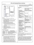
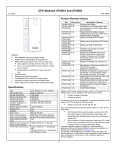
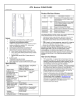
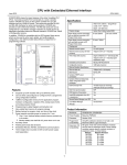
T8 Fingerprint Machine
Hardware User Manual
Date: 2010.03.18
Version: 1.1
(c)2009 Copyright Pegasus Equipments Ltd. All Rights Reserved.
1
Table of Content
Introduction .......................................................................................................................... 3
Installation............................................................................................................................ 3
Menu Structure ..................................................................................................................... 6
User Management ............................................................................................................ 6
Device Management ........................................................................................................ 6
U Disk Management ........................................................................................................ 7
Sys Info ............................................................................................................................ 7
Alarm Reset ..................................................................................................................... 7
Startup Screen ...................................................................................................................... 7
User Management ................................................................................................................ 8
Device Management ............................................................................................................ 9
Basic Setting .................................................................................................................... 9
Advance Setting ............................................................................................................. 10
Schedule Setting............................................................................................................. 12
Log Setting ..................................................................................................................... 12
Comm Setting ................................................................................................................ 13
Door Access Setting ....................................................................................................... 15
Auto Checking ............................................................................................................... 19
USB Disk Management ..................................................................................................... 19
Download Enroll Data ................................................................................................... 19
Download Management Record .................................................................................... 19
Download User Information .......................................................................................... 19
Upload User Information ............................................................................................... 19
Upload Message Transfer .............................................................................................. 19
Upload MP3 ................................................................................................................... 19
Sys Info .............................................................................................................................. 19
Memory .......................................................................................................................... 20
Device Information ........................................................................................................ 21
Advanced Inquiry........................................................................................................... 21
Alarm reset ......................................................................................................................... 22
(c)2009 Copyright Pegasus Equipments Ltd. All Rights Reserved.
2
Introduction
This manual is to teach user the internal structure of T8 and the using of this fingerprint
machine. T8 is a color display time attendance and door access control fingerprint
machine. Its outlook is very attractive.
It is an online fingerprint device which allows you to download data from it in online
mode. You may also choose to download it by offline mode. Besides, it can be used for
door access with full functional time zone management.
Installation
We used to install T8 in the wall. It is because it can avoid strong light shining on the
fingerprint optical sensor. It will seriously affect the recognition ability of the fingerprint
device.
Normally, we will mount the device to the wall in about 1.4 meters high.
Fingerprint machine
1.4 meters
(c)2009 Copyright Pegasus Equipments Ltd. All Rights Reserved.
3
Electric Lock and Alarm Connection
Top down
1. LOCK COM
2. LOCK NC
3. LOCK NO
4. ALARM_COM
5. ALARM_NC
6. ALARM_NO
7. BELL_COM
8. BELL_NC
9. BELL_NO
Push
Gnd
VCC
Gnd
Gnd
Push
NO
GND
NC
AC110/220V
Power supply
Alarm
Electric lock
+
Electric lock
adaptor
Top down
1. VCC5
2. EXIT_BT
3. DOOR_SEN
4. NWGNOUT1
5. NWGNOUT0
6. WGN2_IN1
7. WGN2_IN0
8. GND
+
Push
Button
-
(c)2009 Copyright Pegasus Equipments Ltd. All Rights Reserved.
4
The back of the fingerprint device has a metal rack which can be used to mount the
fingerprint device to the wall.
Communication terminal and power supply
TCP/IP
RS232/485
Power cable
Metal rack
Use screw to
mount the rack
to the wall
(c)2009 Copyright Pegasus Equipments Ltd. All Rights Reserved.
5
Screw for fixing
the rack to the
device
USB device & SD card connection
USB slot for
USB flash
disk and USB
CAM
SD card slot
Cable outlet
Menu Structure
The menu structure of T8 is as follows
User Management
Fingerprint enroll
RF Card enroll
Password enroll
Sound recording
Photo making
Device Management
Basic Setting
Advance Setting
Schedule Setting
Comm Setting
Alert Setting
Door Access Setting
Self Checking
(c)2009 Copyright Pegasus Equipments Ltd. All Rights Reserved.
6
U Disk Management
Download enroll record
Download management record
Download user information
Upload user information
Upload message transfer
Upload MP3
Sys Info
Memory
Device Info
Advanced
Alarm Reset
Startup Screen
When you switch on the machine, a logo will be shown for 3 seconds. The logo is a
bitmap of dimension 320 * 240 pixels. OEM customer can put their bitmap into the
machine to show their company name.
After the logo, you can see a loading screen which shows the process of loading all the
components for the running of the machine. The bottom status bar show the progress of
the loading. When the bottom dark blue bar reaches the end, this screen will be
disappeared.
A waiting screen will be displayed instead. The waiting screen will show the current date
and time. Also, a graph of clock is in left side. If you have set the time status, it will
display it too. Time status is to define the different period of time for different status.
Examples are Duty On or Duty Off.
(c)2009 Copyright Pegasus Equipments Ltd. All Rights Reserved.
7
When the machine is idle for 10 minutes, screen saver will be invoked. The screen saver
consists of 3 pictures. They will be displayed alternatively. Besides, you can hear a short
song for relaxation of the environment.
In the screen saver mode, you can also punch fingerprint or press the “menu” button to
access different menu items.
User Management
In user management, you can add a new user or delete an existing user.
Each user has a unique user ID. When you add a new user, you need to input a user ID
first. The last unused user ID will be shown. If you accept it, you just press <ok>. If not,
you can use numeric button to input the specified user ID. The preceding zero is not
needed. If you want to input 27, just press button “2” and “7” only.
After that, you need to select which verification to register. You can select fingerprint,
card or password. Card is optional.
If you select fingerprint, you need to enroll fingerprint 3 times. The machine will get the
best fingerprint template and store it as a comparing standard.
If you choose card, you need to punch a card to replace the input of card number.
If you choose password, you need to input the password by the numeric keypad
(c)2009 Copyright Pegasus Equipments Ltd. All Rights Reserved.
8
After Registration
If you choose voice, you need to insert SD card first before recording to store voice
record. (not support SDHC) All the voice record will be saved in SD card.
To delete a user, you just input the user ID for deletion.
Before enrollment, we used to have a list of user ID and staff for reference.
User ID
1
2
3
4
Staff Number
MIS001
ACC001
MIS002
SAL001
Name
John
Mary
Peter
Susan
Device Management
Device management is divided into 7 sub menus. They are basic setting, advance setting,
power management, communication management, record management, door access
management and auto check. Each sub menu has a list of menu items for different
argument setting. Use left and right, up and down arrow and go to different menu items.
Basic Setting
Basic setting is the elementary setting of the device. It includes the setting of time, voice,
language, loudness adjustment and button sound.
(c)2009 Copyright Pegasus Equipments Ltd. All Rights Reserved.
9
Time Setting
Time setting is used to set the device and time of the device. After a period of time,
the device time may be varied from the actual time. Using this menu item can correct
the time. The Pegasus software will synchronize the time of the device when you
download data. It guarantees the accuracy of each device when there are many
devices in a network.
Language Setting
You can also set the language of the device. The default language allowed are
English, Traditional Chinese and Simplified Chinese. Customer can request for
making another language such as Thailand or Spanish.
Voice Setting
Voice out on/off is to set the response of the device. When you punch the device
correctly, the device will speak ‘thank you’. If the fingerprint has not been enrolled
or the identification fails, the device will speak ‘press again!’. If you off the voice
out item, the device will not say anything.
When the punch is authorized, it will just give 3 short beep sounds. If it fails, it will
give a long beep sound and the display will show “Press again”.
The voice is located in a sound chip in the main board. The sound chip can only
store one language of voice. So, before leaving the factory, customer need to specify
which language of voice they need.
Loudness Adjustment
It is to adjust the loudness of the voice if you have switch on the voice.
Button Sound
This item is to set whether to have beep sound for pressing button.
Advance Setting
Advance setting is to change the important setup argument for the device. If the
machines has administrator, only administrator can access this menu item. The
submenu items under this includes default verification mode, verification interface,
function key setting, summer time setting, firmware upgrade, restore factory default,
delete all transaction and delete all enroll data.
Default Verification Mode
This item is to set the default verification mode. You can choose
FP
RF+FP
RF
ID+FP
ID+PWD
FP+PWD
RF+PWD
FP means fingerprint, RF means RFID card, ID means user ID. ID+FP means both
user ID and fingerprint need to be verified before you can access.
(c)2009 Copyright Pegasus Equipments Ltd. All Rights Reserved.
10
Verification Interface
This menu item is for FP device with camera. We need to select whether to on the
real time.
Capture of Photo
If we check this option, we need to input the percentage of photo captured by FP,
card and password.
Real time photo capture
FP photo
Card photo
PIN photo
Display Photo
This menu item is for selection of displaying photo after successful verification.
Delete All Transaction
This menu item is to delete all the in out transactions in the machine. Before deletion,
you are asked to confirm again for database security.
Delete all enroll data
This menu item is for deletion of all enroll data in the machine.
Restore Factory Default
This item is for restoring the setting of the device to the factory default. The action
will not affect the enroll data and the existing in out transactions. Again, you are
asked to confirm again for security.
Firmware Upgrade
This item is for upgrading of the machine firmware by USB disk or backend system.
We will do the action when we have new function added or debug of the existing
firmware.
Summer Time Setting
This setting is for summer nation that have summer time. You can make the device
to have faster time starting from a date and have normal time after a end date.
Function Key Setting
The device has 4 function keys for setting different functions (F1 to F4). The default
setting is
F1 = on duty
F2 = off duty
F3 = OT on
F4 = OT off
You can change the setting. For example, F1 can be changed to information inquiry.
F2 can be changed to bell.
(c)2009 Copyright Pegasus Equipments Ltd. All Rights Reserved.
11
Schedule Setting
It consists of a list of menu items for scheduling job. Scheduling job means a specified
job will be invoked at a certain time. The list of menu items includes Power On, Power
Off, Auto Sleep, Bell Setting, Idle Setting and Lock Auto Close.
Auto Power On
The power will be on at a certain time a day. Before power on, the machine is in
sleep mode. For example, you can set the time of 07:00 for auto power on.
Auto Power Off
Auto power off is the opposite of auto power on. It is to preset a time for auto power
off the machine. After off, you can switch on it by power button or the machine will
be on by auto power on. When it is off, the machine is in sleep mode.
Bell Setting
You can set 8 times for the bell to sound (when). Besides, you can set the music for
the bell (what) and the length for the sound (how long). The bell can be output to the
internal speaker or to a external bell which requires independent power.
Idle Timeout Setting
This menu item is for setting the idle time for changing into other status. The default
value is 0 which means disabled. If you set it to 1 minute, the machine will jump to
another status. If no action within one minute, the device will jump to other pre-set
state. The preset state can be sleep or switching off.
Close switch button
This menu item is to off the function of switch button. If it is off, you can only
switch to the machine by unplug and plug power or auto power on.
Schedule status conversion
We can set each time period to have different status such as on duty, off duty, ot
arrive, ot leave. You can have 6 times for setting status and the maximum status is 4.
Log Setting
Log Setting is to set the alert threshold for giving warning message in the device display.
You can set 3 warning threshold. They are MLog Warning, GLog Warning and Reverify
Time.
(c)2009 Copyright Pegasus Equipments Ltd. All Rights Reserved.
12
MLog Warning
Mlog Wrn means Management Log warning threshold. Management Log means the
record for changing the menu items. It is to set the number of record space remaining
for giving warning message. The default threshold is 100. That is, when the
remaining space can only stores 100 records, the display will show warning message
for you to download the management log records or to clear them.
GLog Warning
Glog Wrn means the general log warning threshold. General Log means the punch
transaction. Each in represent one record and each out represent also one record.
When the remaining space can store less than this figure, the display will show error
message. You are supposed to download the transaction immediately or you will loss
the previous punch records.
Reverify Time
This menu item is to set the number of seconds to prevent duplicate punch of the
same user identifier. The default is zero. It means you can punch many times without
control. It will waste the space of the device in storing useless records. So, customer
can set this figure to a number of seconds. The maximum number of seconds
allowed to be set is 255 seconds.
Comm Setting
The communication setting is mainly for management of communication between device
and computer. It will set the parameters for the successful communication. It includes the
baud rate, device ID, TCP/IP, RS232, RS485, CommPassword, DHCP and Manager PC
IP Address
Baud rate
Baud rate is the parameter for both the RS232 and RS485 communication. The
default rate is 115,200 bits per second. Normally, we will use this baud rate without
the need for changing.
Device ID
(c)2009 Copyright Pegasus Equipments Ltd. All Rights Reserved.
13
Device ID is the unique identifier for each device in an environment. If you have
more than one device in your network, you need to have unique device ID. If three
devices in a network, we need to set those device ID to 1, 2 and 3 differently. Each
device will have a default device id of 1.
TCP/IP
In this item, we can set the configuration related to the TCP/IP connection.
We can set the IP address of the fingerprint device. The default IP address is
192.168.0.9. This is the identity of the fingerprint device in the network.
RS232
This item is to on/off the RS232 communication. The package of T8 includes a
RS232 cable. The maximum distance for RS232 communication is 5 meters.
If your computer does not have com port, you can add a RS232-USB converter to
connect with the USB port of the computer
The fingerprint device uses the D-type 9 pin socket for connecting the RS232 cable.
The pin assignment is as follows.
Pin 2 = TX, Pin 3 = RX, Pin 5 = GND, Pin 1,4,6,7,8,9 = NC.
1
2
6
3
7
5
6
4
8
9
RS485
We can choose whether to on the RS485 communication. It has a maximum distance
of 200 meters. Normally, we will use RS485 cable to connect between fingerprint
device and computer. Also, we can use category 5 cable to replace RS485 cable as it
is much more common.
Computer does not have RS485 communication protocol. It only has RS232
communication protocol. So, we need a converter to convert RS485 signal to RS232
signal.
T8
(c)2009 Copyright Pegasus Equipments Ltd. All Rights Reserved.
14
RS485 signal
Cat5 cable
RS232 signal
converter
Com port
The RS485 communication uses 3 wires. One is TX+. The second is TX-. The third
is Ground.
RS485-to-RS232 converter
RS485 cable uses the same RJ45 socket for communication. The pin assignment is
as follows:
Pin 5 = RS485A, Pin 6 = RS485B, Pin 1 = GND
CommPassword
We need a communication password for communication. It is to prevent other person
to use the similar software to connect to the device. The default communication
password is one zero (0).
DHCP
This is to on/off the Dynamic Host Control Protocol. DHCP is for assigning IP
address to the device by DHCP host in the network.
Manager PC IP addr
This is the backend computer IP address. The computer will send arguments to the
device for management of the time attendance machine. One example is to send the
user message into the device.
Door Access Setting
Door Access is based on a set of time zones, a set of groups having these time zones and
the assignment of time zones and groups to user. Each time zone has a list of open time
by day of week., Sunday to Saturday. Each user can open door at any time from its group
or its time zones. Their relationship is “or”. For example, if time zone 1 has
Sunday
08:00 – 19:00
Monday
08:00 – 19:00
Tuesday
08:00 – 19:00
(c)2009 Copyright Pegasus Equipments Ltd. All Rights Reserved.
15
Wednesday
Thursday
Friday
Saturday
08:00 – 19:00
08:00 – 19:00
08:00 – 19:00
08:00 – 19:00
Time zone 2 has
Sunday
21:00 – 23:00
Monday
21:00 – 23:00
Tuesday
21:00 – 23:00
Wednesday 21:00 – 23:00
Thursday
21:00 – 23:00
Friday
21:00 – 23:00
Saturday
21:00 – 23:00
User “John” has been assigned for both time zone 1 and time zone 2. So, John can open
door from 08:00 to 19:00 and 21:00 to 23:00 every day. Besides, we can set 10 time
match. Each time match consists of maximum of 3 groups. If you choose 2 groups, any
user from the 2 groups must be punch together for successful access.
Time zone setting
It is to set the open door time range in a week. We can define a maximum of 50 time
zones. You only need to input hour and minute. Time zone 1 allows open door by all
time.
Sunday
00:00 – 23:59
Monday
00:00 – 23: 59
Tuesday
00:00 – 23: 59
Wednesday 00:00 – 23: 59
Thursday
00:00 – 23: 59
Friday
00:00 – 23: 59
Saturday
00:00 – 23: 59
Use <up> or <down> arrow to choose a time zone and press <ok> to go into day of
week.
Time group setting
Totally, you can set up to 5 groups. For each group, you can assign maximum of 3
time zones to the group. After that, the group will have all the open time of its time
zones. New user will have default group of group 1. Select the group by up/down
arrow and input the time zone number (1 to 50).
Group Verification Mode Setting
In this item, you can set the device default verification mode. There are 8
verification mode.
FP or RF or PWD
FP
RF and FP
RF
ID and FP
ID and PWD
FP and PWD
(c)2009 Copyright Pegasus Equipments Ltd. All Rights Reserved.
16
RF and PWD
User Door Access Setting
We can assign a list of door access parameter to each user.
User
Group
Use Group Time zone
Time zone 1
Time zone 2
Time zone 3
Use Group Verification
Verify Mode
000001
1
Yes
1
8
40
Yes
FP
The user can be assigned to a group so that the user will have the group time zone
open time. If the argument “use group timezone” is set to “yes”, the 3 time zone
number will be equal to the time zone number under the group.
For example, if user 0001 uses group time zone 3 group time zones 3 has time zones
7,8,9.Then, the 3 time zone numbers will be 7, 8, 9 correspondly. If we change the
time zone number, the “use group time zone” will be changed to “no” automatically.
Time Match
We can select either “basic setting” or “group setting”. In basic setting, we just set
number of user needed to open door. The default setting is 1. That is, when 1 user
pass the verification, the door will be opened. You can set to maximum figure of 5. If
you set it to 2, it means the door will be opened only if 2 users can pass the
verification within 30 seconds.
User 1 pass
User 2 pass
15 seconds
Door open
User 1 pass
User 2 pass
31 seconds
Door not open
The system will not care which group the 2 users belong to. Open door group allows
a 1 to 3 groups combination for door access. We can have 10 open door group. For
example, open door group 1 has combination of 1, 2 and 3. It means that any user for
each group must pass the verification for door access.
Another example, open door group 2 has only group 4. Any member from group 4
can open the door.
(c)2009 Copyright Pegasus Equipments Ltd. All Rights Reserved.
17
Lock Control Time
Lock control time is the time between verification pass and the sending of signal to
door lock adaptor.
Open door
Check time
The minimum unit is 0.5 seconds. The maximum value is 5 seconds. If it is set to 0,
the door lock control will be closed.
Door Sensor Delay
Door sensor delay is the time between the door open and the checking of door sensor.
If the door sensor status is different from the preset door status, alarm will be
invoked. The unit for it is second.
Door sensor on/off setting
It consists of 3 types. They are none, always open and always close. None means we
do not use door sensor on/off. Always open means if door is opened, lock should
also be kept opened. If it is not the case, alarm will be invoked after the door sensor
delay time. Always close means if door is closed, the lock should also be locked.
Otherwise, alarm will be invoked after the door sensor delay time.
Duress Alarm Setting
If duress fingerprint is being punched, the alarm will be invoked after a period. This
item is to prevent someone push the other to get access. Normally, a user will enroll
2 normal fingerprints and reserve one fingerprint as duress fingerprint. When he is
forced to open door, he will use the duress fingerprint.
Power Checking Alarm
We can choose to on/off this alarm function.
Button Pressing Help
If we switch on this item, pressing down arrow “▼” for over 3 seconds will create
help signal. If we press “ “ for over 3 seconds and then press fingerprint or input user
ID, verified password will cause the duress alarm to be invoked. To off this item, just
set it to false.
Alarm Delay
This menu item is for setting the delay time for auto alarm to be on. When duress
signal happens, the alarm will not be on immediately. It will be on after this alarm
delay time (0 to 255 seconds).
Wrong Punch Alarm
This is to set number of times in wrong punch for the alarm to be invoked. When the
failure verification time reaches this figure, alarm will be invoked. Setting to zero
means disabling this function. We can set this from 1 to 9 times. The default setting
is 3 times.
(c)2009 Copyright Pegasus Equipments Ltd. All Rights Reserved.
18
Auto Checking
Sometimes, when you found the device has problem, you can use this menu item to
troubleshoot the cause of the problem. Once the problem can be identified, you can solve
it. This auto checking includes the testing of storage, LCD, voice, fingerprint sensor,
keyboard and time. Please be reminded that the power should be kept stable in the power
of checking. Otherwise, the hardware may be damaged, especially in the checking of
storage.
USB Disk Management
This main item includes a list of menu items for setting up the device by USB disk. It
includes
Download enroll data
Download management record
Download user information
Upload user information
Upload message information
Upload MP3
Download Enroll Data
It is to download the user enroll data into USB disk. A user ID may have several
fingerprints and/or card and/or password. All these data will be downloaded too.
Download Management Record
It is to download the management setup record into the USB disk. Any change of the
device setting will be recorded in the device and download to the USB disk.
Download User Information
It is to get the user manage from the device to USB disk. User message is the message
displayed in the device for different user when she passes the verification.
Upload User Information
It is the opposite of downloading user information. It gets the file from USB disk back
to the device.
Upload Message Transfer
This is to upload message for transferring.
Upload MP3
It is to upload the screen saver music and pictures from USB disk to the device.
(Message Remark: You can upload message from Uion Attendance Management
System Software to machine through TCP/IP, RS232 and RS485 communication.)
Sys Info
This main item is for inquiry of information in the device. We have divided this
information into 3 categories. They are memory, device information and advance inquiry.
(c)2009 Copyright Pegasus Equipments Ltd. All Rights Reserved.
19
Memory
It is to check the used and remain storage quantity of different arguments. These 2 figures
are separated by a stroke “/”.
It includes
Enroll count
Fingerprint enroll
Password enroll count
Card enroll count
GLog count
MLog count
Used space
Enroll count means the user enroll count. Fingerprint enroll means the fingerprint used
and remaining quantities. Password enroll count is the enrolled password quantities. Card
enroll count is the RFID card enrolled. GLog count is the general log (in/out transaction).
MLog count is the management record count. Used space is the physical storage used and
remained
(c)2009 Copyright Pegasus Equipments Ltd. All Rights Reserved.
20
Device Information
Device Information pinpoints the information in the device. It includes
Factory production date
Serial number
Manufacturer
Device management
Device model
Algorithm version
Firmware version
Advanced Inquiry
It is for combination of input to create the query. It includes the GLog view, MLog view
and Enroll View.
GLog view is the general log record inquiry (in/out transaction). MLog view is the
management log record inquiry. Enroll view is the inquiry of enroll information for each
user.
For each inquiry, you need to input the date range and user ID or user name.
(c)2009 Copyright Pegasus Equipments Ltd. All Rights Reserved.
21
Alarm reset
This menu item cannot be seen when there is no alarm signal. When there is alarm signal,
you will see this menu item. Selecting this menu item will off the alarm.
*** The End ***
(c)2009 Copyright Pegasus Equipments Ltd. All Rights Reserved.
22