1
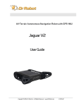
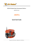
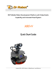
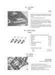
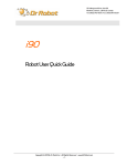
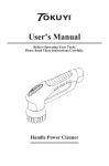
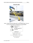
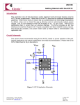
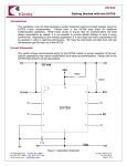
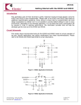
25 Valleywood Drive, Unit 20 Markham, Ontario, L3R 5L9, Canada Tel: (905) 943-9572 Fax: (905) 943-9197 [email protected] Dr Robot ® C# Advance Sentinel2 Demo Program Version: 1.0.0 June 2008 Copyright © 2008, Dr Robot Inc. All Rights Reserved. www.DrRobot.com -1- Copyright Statement This manual or any portion of it may not be copied or duplicated without the expressed written consent of Dr Robot. All the software, firmware, hardware and product design accompanying with Dr Robot’s product are solely owned and copyrighted by Dr Robot. End users are authorized to use for personal research and educational use only. Duplication, distribution, reverse-engineering, or commercial application of the Dr Robot or licensed software and hardware without the expressed written consent of Dr Robot is explicitly forbidden. Copyright © 2008, Dr Robot Inc. All Rights Reserved. www.DrRobot.com -2- Table of Contents 1 Prepare 4 2 User Interface 5 Copyright © 2008, Dr Robot Inc. All Rights Reserved. www.DrRobot.com -3- 1 Prepare 2 To use Sentinel Demo programs, you need download some support programs from Dr Robot and install or register them. Here is the list: 1. DRROBOTSentinelCONTROL.OCX This ActiveX control component needs be copied to windows/system32 folder and use regsvr32 to register it. 2. WiRobotGatewayforWiFi.exe You can copy it to your working folder. 3. DrRobotSensorMapBuilder.dll This dll file provides some functions to build around sensor map for collision avoidance. It needs to be copied to “windows/system32” folder and use regsvr32 to register it. 4. DrRobotConstellation.dll 2 For Sentinel , you will need this file. This dll file provides some functions to local the robot position with DrRobot Constellation system. It needs to be copied to “windows/system32” folder and use regsvr32 to register it. 5. DrRobotP2PSpeedDrive.dll This dll file provides some functions to make robot move form one point to another point. It needs to be copied to “windows/system32” folder and use regsvr32 to register it. 6. Install DirectX9.0C for Joystick control in program. 7. VitaminCtrl.dll 2 2 For I90 series, Sentinel and Scout , you need to install camera control component. You can download VitaminDecoder.exe to install it. Note: For DRROBOTSentinelCONTROL.OCX, you can refer to Dr Robot SDK API User Manual. Copyright © 2008, Dr Robot Inc. All Rights Reserved. www.DrRobot.com -4- 2 User Interface There are two DrRobotSentinelControl ActiveX controls in this program, and you need to run first one WiRobotGatewayforWiFi.exe program and set Robot ID as “power”, type in your robot IP and set Port as “10001” (default), and click “Connect” button. And then run second WiRobotGatewayforWiFi.exe program and set Robot ID as “motion”, type in your robot IP and set Port as “10002” (default) WiRobotGatewayforWiFi.exe Port Number: 10001 Power Management PC WiFi module-I Port Number: 10002 Motion Control WiFi module –II Channel –II Port 10002 Constellation System Camera IP 192.168.0.199:8081 Sentinel 2 Router 192.168.0.200 Controller Boards Connection Diagram Copyright © 2008, Dr Robot Inc. All Rights Reserved. www.DrRobot.com -5- Open the project and click F5 button to run the program. Tag: Main Sensor Info 1. Camera Click connection status to connect to camera, yellow text box display currently Copyright © 2008, Dr Robot Inc. All Rights Reserved. www.DrRobot.com -6- 2. Camera Control Click , the image should be saved at c:\ drive as “temp1.jpg”, you can modify store path Click to store the video at “..\DrRobotSentinel2Demo\bin\Debug\” folder with CLIP_YYYYMMDD-HHMMSS.avi, you can modify store path Click , the camera should pan Click to stop camera movement Click to set the camera to original initial position. Note: For more camera function sample, please refer to CD’s “\PTZ Camera SDK\ “ folder 3. Range Sensor 4. 5. List the sensor reading Motor Sensor List Encoder reading option, the motor should auotmatic stop once Checked the motor overheat or got stuck. Position Information Copyright © 2008, Dr Robot Inc. All Rights Reserved. www.DrRobot.com -7- List currently position value from encoder and from constellation system Checked 6. to receive constellation position information Board Sensor 7. List the board and motor ‘s power voltage. Human Sensor 8. List left and right human motion sensor reading Extend IO List Input IO value Click to set the Output IO parameter, “0” for “00000000” and “255” for “11111111”. For detail , refer to X80 User manual 9. Motion control -> Set Drive Power Drive robot via PWM value, value must between 0 ~ 32767, set 16384 to stop motor Copyright © 2008, Dr Robot Inc. All Rights Reserved. www.DrRobot.com -8- 10. Motion control -> Set Drive Speed 11. Motion Control -> Set Rotate Degree 12. Set “Degree” to “45”, robot should turn left 45°, set “-45”, robot should turn right 45°, set “720”, robot should turn 2 circle. Motion Control -> Set Drive Distance 13. Drive robot via encoder speed Drive robot to designed distance, unit is meter. Motion Control -> Chassis Control Copyright © 2008, Dr Robot Inc. All Rights Reserved. www.DrRobot.com -9- Click the arrow button to drive robot “Forward”, “Backward”, “Turn Left”, “Turn Right” and “Stop” Adiust Speed Scroll bar to change the motion speed. Note: If you can not find the perfect speed for your robot, you can modify this scroll bar’s maximum value. 14. Motion -> Direct Input Device Check , drive the robot via Joystick, push the handheld stick forward, the robot drives forward, for faster speed, just push bigger range. Click when you drive robot via Joystick. 15. Motion -> Direct Input Device -> Joystick send out Wheel Power 16. to active “Collision Avoidance” function Display currently PWM value for driving robot Power State Copyright © 2008, Dr Robot Inc. All Rights Reserved. www.DrRobot.com - 10 - Display 2 battery packs currently state, include voltage and temperature When you plug in the charger plug into robot, the DCIN should display charger voltage. 17. Power Path Control Checked , the robot only use battery – I Checked , the robot only use battery –II Checked , the robot power by charger unit By default, robot uses both battery packs 18. Charge Path Control Checked to only charge battery –I Checked to only charge battery -II By default, both battery packs should be chargered display the charger process status Click If the temperature of battery packs is high, the charger task should automatic stop. The charger process status bar should stop. 19. to stop charger task Charge current Control Selected option for full current charge Selected option for half current charge Copyright © 2008, Dr Robot Inc. All Rights Reserved. www.DrRobot.com - 11 - Selected option for 1A current charge Selected option for 300mA charge 20. Power Switch Control Selected ON/OFF for Channel – I , this should reset Camera power Select ON/OFF for Channel – II, this should reset motion power Select ON/OFF for Channel – III, this channel is reserved Tag: Path Control Copyright © 2008, Dr Robot Inc. All Rights Reserved. www.DrRobot.com - 12 - 1. Robot Path Control Information 2. Path Control Panel to select Path file Click to execute the task Click to stop robot movement for select the task, when you select “Wander Task”, the robot will wandering with collision avoidance. To implant this function, the program will set the target point just at 1m front of current position in tmrControl. Almost same for Joystick control with Collision avoidance, it also is implemented by calling P2P drive function and always set the target point at the 1m front of current position. There is simple map display at the interface. You can change the mapratio and map center(0,0) position to display the robot position. If you checked , you choose the target point by click the mouse on the map area, and the program will display the point at the map and you can click button to drive the robot. When you select “P2P task”, Point to Point, robot will drive to points one by one and stop at the last point. you need to provide the path file, if there are 3 points in your file, robot should start from point 1 and access point 2 and arrive point 3 and stop. Selected this option, and then you can click to drive the robot. button When you select “Charge Task”, You need to write a charge path for charge station. Usually it has at least 4 points before the charge station. The last point should be behind the charge station around 20 cm. and the last second point should be at the 10cm front of charge station. You can get the point information by Copyright © 2008, Dr Robot Inc. All Rights Reserved. www.DrRobot.com - 13 - putting the robot at the desired points and writing down the position data in the charge path file. There are more detection and output in tmrControl function to detect the chargestation(input IO bit 0 is zero) and set the output IO bit 0 as high to enable the charge station output the power. And at the last three points you need to switch transponder to Chargestation transponder, to improve the accuracy for estimate. You can read the source code to get more details. You can write you own code to plan the path and in big area auto switch the transponder and detect the battery power to implement a auto go to charge station function. Charge Station The last point When you select “Patrol Task” Point to Point, robot will drive to points one by one and robot will not stop at the last point, it will run to the first the point. You need carefully to write the patrol path file. if there are 3 points in your file, robot should start from point 1 and access point 2 and point 3 and return to point 1 and run again and again until you click . for adjust the speed for zoom in or zoom out map, increase value should zoom out the map. for set the location of centrol point (Red dot) in the picture option, use mouse to click on map, a checked “Target Point” (White dot) should present on the map, the robot should run to this target point. Copyright © 2008, Dr Robot Inc. All Rights Reserved. www.DrRobot.com - 14 - Tag: Constellation & SensorMap 21. Constellation System Connection to connect constellation system, once successful connect Click to constellation, the position information should display. Currently constellation info also display as above picture. 22. Configure teansponder ID Copyright © 2008, Dr Robot Inc. All Rights Reserved. www.DrRobot.com - 15 - Click to config the transponder ID, for detail information, please 2 refer to Sentinel User manaul 23. SensorMap Display currently obstacle status which detected by range sensors (Ultrasonic & IR Sensors) Copyright © 2008, Dr Robot Inc. All Rights Reserved. www.DrRobot.com - 16 -